

Page 1

Network
Application Platforms
Hardware platforms for next generation networking infrastructure
HCP-72i1
V1.0
User's Manual
Release Date: 2015/06/19
www.lannerinc.com
Page 2
2
www.lannerinc.com
Overview
Icon Descriptions
The icons are used in the manual to serve as an
indication of interest topics or important messages.
Below is a description of these icons:
NOTE: This check mark indicates
that there is a note of interest and is
something that you should pay special
attention to while using the product.
WARNING: This exclamation point
indicates that there is a caution or
warning and it is something that could
damage your property or product.
Online Resources
The listed websites are links to the on-line product
information and technical support.
Resource Website
Lanner http://www.lannerinc.com
Product
Resources
http://www.lannerinc.com/downloadcenter/
RMA http://eRMA.lannerinc.com
Copyright and Trademarks
This document is copyrighted, © 2014 All rights are
reserved. The original manufacturer reserves the right to
make improvements to the products described in this
manual at any time without notice.
No part of this manual may be reproduced, copied,
translated or transmitted in any form or by any means
without the prior written permission of the original
manufacturer. Information provided in this manual
is intended to be accurate and reliable. However, the
original manufacturer assumes no responsibility for its
use, nor for any infringements upon the rights of third
parties that may result from such use.
Acknowledgement
Intel, Pentium and Celeron are registered trademarks of
Intel Corp.
Microsoft Windows and MS-DOS are registered
trademarks of Microsoft Corp.
All other product names or trademarks are properties of
their respective owners.
Compliances
CE
This product has passed the CE test for environmental
specifications. Test conditions for passing included
the equipment being operated within an industrial
enclosure. In order to protect the product from being
damaged by ESD (Electrostatic Discharge) and EMI
leakage, we strongly recommend the use of CEcompliant industrial enclosure products.
FCC Class A
This equipment has been tested and found to comply
with the limits for a Class A digital device, pursuant
to Part 15 of the FCC Rules. These limits are designed
to provide reasonable protection against harmful
interference when the equipment is operated in a
commercial environment. This equipment generates,
uses and can radiate radio frequency energy and, if not
installed and used in accordance with the instruction
manual, may cause harmful interference to radio
communications. Operation of this equipment in a
residential area is likely to cause harmful interference
in which case the user will be required to correct the
interference at his own expense.
Safety Guidelines
Follow these guidelines to ensure general safety:
Keep the chassis area clear and dust-free during •
and after installation.
Do not wear loose clothing or jewelry that could •
get caught in the chassis. Fasten your tie or scarf
and roll up your sleeves.
Wear safety glasses if you are working under any •
conditions that might be hazardous to your eyes.
Do not perform any action that creates a potential •
hazard to people or makes the equipment unsafe.
Disconnect all power by turning off the power and •
unplugging the power cord before installing or
removing a chassis or working near power supplies
Do not work alone if potentially hazardous •
conditions exist.
Never assume that power is disconnected from a •
circuit; always check the circuit.
Page 3

3
www.lannerinc.com
LITHIUM BATTERY CAUTION:
Risk of Explosion if Battery is replaced by an incorrect
type. Dispose of used batteries according to the
instructions
Operating Safety
Electrical equipment generates heat. Ambient air
temperature may not be adequate to cool equipment to
acceptable operating temperatures without adequate
circulation. Be sure that the room in which you choose to
operate your system has adequate air circulation.
Ensure that the chassis cover is secure. The chassis design
allows cooling air to circulate effectively. An open chassis
permits air leaks, which may interrupt and redirect the
flow of cooling air from internal components.
Electrostatic discharge (ESD) can damage equipment
and impair electrical circuitry. ESD damage occurs when
electronic components are improperly handled and can
result in complete or intermittent failures. Be sure to
follow ESD-prevention procedures when removing and
replacing components to avoid these problems.
Wear an ESD-preventive wrist strap, ensuring that it
makes good skin contact. If no wrist strap is available,
ground yourself by touching the metal part of the
chassis.
Periodically check the resistance value of the antistatic
strap, which should be between 1 and 10 megohms
(Mohms).
EMC Notice
This equipment has been tested and found to comply
with the limits for a Class A digital device, pursuant
to Part 15 of the FCC Rules. These limits are designed
to provide reasonable protection against harmful
interference when the equipment is operated in a
commercial environment. This equipment generates,
uses, and can radiate radio frequency energy and, if not
installed and used in accordance with the instruction
manual, may cause harmful interference to radio
communications. Operation of this equipment in a
residential area is likely to cause harmful interference
in which case users will be required to correct the
interference at their own expense.
Consignes de sécurité
Suivez ces consignes pour assurer la sécurité générale :
Laissez la zone du châssis propre et sans poussière •
pendant et après l’installation.
Ne portez pas de vêtements amples ou de bijoux qui •
pourraient être pris dans le châssis. Attachez votre
cravate ou écharpe et remontez vos manches.
Portez des lunettes de sécurité pour protéger vos •
yeux.
N’effectuez aucune action qui pourrait créer un •
danger pour d’autres ou rendre l’équipement
dangereux.
Coupez complètement l’alimentation en éteignant •
l’alimentation et en débranchant le cordon
d’alimentation avant d’installer ou de retirer un
châssis ou de travailler à proximité de sources
d’alimentation.
Ne travaillez pas seul si des conditions dangereuses •
sont présentes.
Ne considérez jamais que l’alimentation est coupée •
d’un circuit, vérifiez toujours le circuit. Cet appareil
génère, utilise et émet une énergie radiofréquence
et, s’il n’est pas installé et utilisé conformément aux
instructions des fournisseurs de composants sans
fil, il risque de provoquer des interférences dans les
communications radio.
Avertissement concernant la pile au
lithium
Risque d’explosion si la pile est remplacée par une •
autre d’un mauvais type.
Jetez les piles usagées conformément aux •
instructions.
L’installation doit être effectuée par un électricien •
formé ou une personne formée à l’électricité
connaissant toutes les spécifications d’installation et
d’appareil du produit.
Ne transportez pas l’unité en la tenant par le câble •
d’alimentation lorsque vous déplacez l’appareil.
La machine ne peut être utilisée qu’à un lieu fixe •
comme en laboratoire, salle d’ordinateurs ou salle de
classe.
Sécurité de fonctionnement
L’équipement électrique génère de la chaleur. La •
température ambiante peut ne pas être adéquate
pour refroidir l’équipement à une température de
fonctionnement acceptable sans circulation adaptée.
Vérifiez que votre site propose une circulation d’air
adéquate.
Vérifiez que le couvercle du châssis est bien •
fixé. La conception du châssis permet à l’air de
refroidissement de bien circuler. Un châssis ouvert
laisse l’air s’échapper, ce qui peut interrompre et
rediriger le flux d’air frais destiné aux composants
internes.
Les décharges électrostatiques (ESD) peuvent •
endommager l’équipement et gêner les circuits
électriques. Des dégâts d’ESD surviennent lorsque
des composants électroniques sont mal manipulés et
peuvent causer des pannes totales ou intermittentes.
Suivez les procédures de prévention d’ESD lors du
retrait et du remplacement de composants.
- Portez un bracelet anti-ESD et veillez à ce qu’il soit
bien au contact de la peau. Si aucun bracelet n’est
disponible, reliez votre corps à la terre en touchant la
Page 4
4
www.lannerinc.com
Consignes de sécurité électrique
Avant d’allumer l’appareil, reliez le câble de mise à la •
terre de l’équipement à la terre.
Une bonne mise à la terre (connexion à la terre) est •
très importante pour protéger l’équipement contre
les effets néfastes du bruit externe et réduire les
risques d’électrocution en cas de foudre.
Pour désinstaller l’équipement, débranchez le câble •
de mise à la terre après avoir éteint l’appareil.
Un câble de mise à la terre est requis et la zone •
reliant les sections du conducteur doit faire plus de 4
mm2 ou 10 AWG.
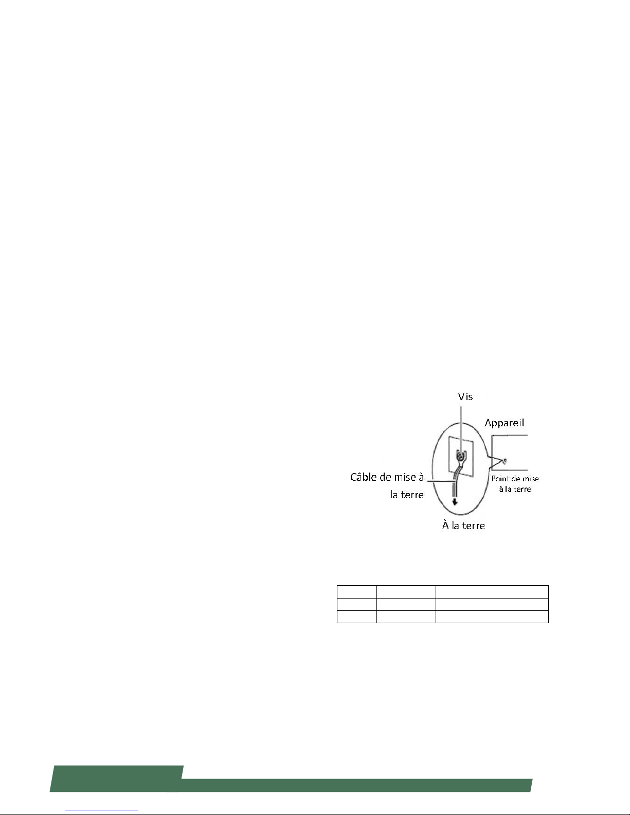
Procédure de mise à la terre pour source
d’alimentation CC Procédure de mise à la
terre pour source d’alimentation CC
Desserrez la vis du terminal de mise à la terre. •
Branchez le câble de mise à la terre à la terre.•
L’appareil de protection pour la source •
d’alimentation CC doit fournir 30 A de courant.
Cet appareil de protection doit être branché à la
source d’alimentation avant l’alimentation CC.
Revision History
Version Date Descriptions
V0.1 2014/12/09 Preliminary
V1.0 2015/06/19 Ocial release
partie métallique du châssis.
Vérifiez régulièrement la valeur de résistance du bracelet
antistatique, qui doit être comprise entre 1 et 10
mégohms (Mohms).
Consignes de sécurité électrique
Avant d’allumer l’appareil, reliez le câble de mise à la •
terre de l’équipement à la terre.
Une bonne mise à la terre (connexion à la terre) est •
très importante pour protéger l’équipement contre les
effets néfastes du bruit externe et réduire les risques
d’électrocution en cas de foudre.
Pour désinstaller l’équipement, débranchez le câble de •
mise à la terre après avoir éteint l’appareil.
Un câble de mise à la terre est requis et la zone reliant •
les sections du conducteur doit faire plus de 4 mm2 ou
10 AWG.
Procédure de mise à la terre pour source
d’alimentation CC Procédure de mise à la
terre pour source d’alimentation CC
Desserrez la vis du terminal de mise à la terre. •
Branchez le câble de mise à la terre à la terre.•
L’appareil de protection pour la source d’alimentation •
CC doit fournir 30 A de courant.
Cet appareil de protection doit être branché à la source
d’alimentation avant l’alimentation CC.
pour refroidir l’équipement à une température de •
fonctionnement acceptable sans circulation adaptée.
Vérifiez que votre site propose une circulation d’air
adéquate.
Vérifiez que le couvercle du châssis est bien fixé. La •
conception du châssis permet à l’air de refroidissement
de bien circuler. Un châssis ouvert laisse l’air s’échapper,
ce qui peut interrompre et rediriger le flux d’air frais
destiné aux composants internes.
Les décharges électrostatiques (ESD) peuvent •
endommager l’équipement et gêner les circuits
électriques. Des dégâts d’ESD surviennent lorsque
des composants électroniques sont mal manipulés et
peuvent causer des pannes totales ou intermittentes.
Suivez les procédures de prévention d’ESD lors du
retrait et du remplacement de composants.
- Portez un bracelet anti-ESD et veillez à ce qu’il soit bien
au contact de la peau. Si aucun bracelet n’est disponible,
reliez votre corps à la terre en touchant la partie
métallique du châssis.
Vérifiez régulièrement la valeur de résistance du bracelet
antistatique, qui doit être comprise entre 1 et 10
mégohms (Mohms).
Page 5

5
www.lannerinc.com
Table of Contents
Chapter 1: Introduction 10
System Specification 10
Package Contents 11
Block Diagram 12
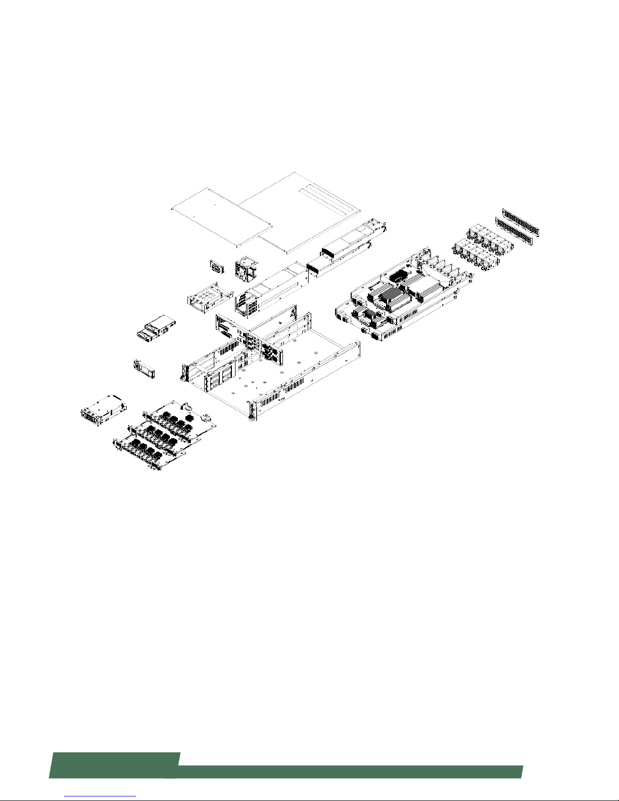
Physical Architecture of Lanner’s HybridTCA 13
Chapter 2: System Components 15
Mechanical Drawings 15
Front Components 16
Rear Components 17
Chapter 3: Motherboard Information 19
An Internal Glance of HCP-72i1 19
Jumper and Connector Location 21
Connectors and Jumpers List 22
Jumper Settings & Connectors Pin Definitions 23
Chapter 4: Hardware Installation 27
Preparing the Hardware Installation 27
Accessing the Components 27
Installing CPU and the Heat Sink 28
Installing the System Memory 29
Installing IPMI Card on OPMA Socket 29
Installing HDD/SSD 30
Replacing Network I/O Modules 31
Replacing Power Supply Units 31
Page 6

6
www.lannerinc.com
Replacing Cooling Fans 32
Rack Mounting 33
Chapter 5: BIOS Setup 36
Main 37
Advanced 38
WHEA Configuration 40
CPU Configuration 41
SATA Configuration 46
USB Configuration 48
Hardware Monitor 51
LAN Module Hardware Monitor 52
LAN Boot Select 53
Serial Port Console Redirection 54
COM Console Redirection Settings 55
Chipset 60
IOH Configuration 61
Intel (R) VT for Directed I/O Configuration 62
Boot 68
Security 75
Save & Exit 76
Chapter 6: IPMI Navigation 78
Getting Started 78
Dashboard 79
Remote Control 79
Remote Control -- Launched 80
Introducing the Remote Control Functions 81
Page 7

7
www.lannerinc.com
Configuration 87
DNS Server Settings 87
Mouse Mode Settings 88
Network Settings 89
Network Link Configuration 90
NTP Settings 91
Services 91
SSL Certificate Configuration 92
User Management 93
Remote Control 94
Console Redirection 94
Server Power Control 95
Maintenance 95
Firmware Update 96
Restore Factory Defaults 96
System Administrator 96
Chapter 7: About the PCIe-Switch Feature of HCP-72i1 98
Brief 98
Default Settings of PCI Express Switch 99
Demonstrating the Switching Methods for the PCIe Switch 99
Initializing the System for Re-planning the Arrangement of PCI Bus ID 100
Scenario 1: Bottom Board as Management Port, Device 2/3 Taken by Bottom Board 101
Scenario 2: Bottom Board as Management Port, Device 2/3 Returned to Upper Board 104
Description of PLX8748 Register 105
Management of the Control Register 105
Secondary Bus Reset 105
Virtual Switch 105
Page 8

8
www.lannerinc.com
Appendix 1: About the Non-Transparent Bridge 106
Appendix 2: Programming Watchdog Timer 110
Appendix 3: Setting up Console Redirections 110
Appendix 4: Programming the LCM 111
Appendix 5: On Linux 114
Appendix 6: Terms and Conditions 115
Warranty Policy 115
RMA Service 115
Page 9

9
www.lannerinc.com
Chapter 1
Introduction
Page 10

10
www.lannerinc.com
Chapter 1:
Introduction
Thank you for choosing HCP-72i1. HCP-72i1 is a
2U rackmount network security appliance built
with Lanner’s unique Hybrid Telecommunications
Computing Architecture (HybridTCA™).
HCP-72i1 integrates control, management and data
processing in one system and is positioned as an ideal
solution for datacenters and telecommunications
carriers. It comes with two x86 mainboards, each
supporting two Intel Xeon E5-2600 series “Ivy Bridge EP”
processors on LGA2011.
HCP-72i1 can be fitted, via the three (max.) swappable
I/O blades, with up to 36 1GbE network ports or 24
10GbE network ports in an array of SFP or copper
combinations. This particular appliance also comes with
8 quad-channel DDR3 modules and 2 removable SAS/
SATA HDD bays, future-proofing most of the expansion
needs.
SFeatures:
Intel Sandy/Ivy Bridge EP Xeon® Processor E5-2697 •
v2 CPUs, with Patsburge-B 602 PCH
2 x86 CPU Blades in the rear, each blade support •
Ivy-Bridge E5-2600 v2 Family up to 130W CPU
Dual Mainboard Communication is through NTB •
port up to 20 Gbs bi-way
Each Blade Support 16x R-DIMM•
3 network I/O Blades on the front•
IPMI Port for Remote Management•
Removable Fan Module•
NEBS Ready Design•
2 x 2.5” HDD Bay•
Hinge LCD Module for Easy Diagnostics and •
Configuration
System Specification
Form Factor 2U Rackmount
Platform
Processor
Options
Intel Sandy / Ivy Bridge EP (Intel®
Xeon® Processor E5-2697 v2 (30M
Cache, 2.70 GHz)
Dual 2011 pin LGA sockets
Chipset Intel Patsburg-B 602
BIOS
64Mb Flash Memory with AMI®
BIOS
System
Memory
Technology
16 x 240-pin DIMM Sockets per
board
Max. Capacity
Up to 32GB DDR3 1600 ECC Registered DIMM
Socket 16 x 240-pin DIMM Sockets
OS Support
Supports 32-bit/64-bit
operating systems
Storage HDD Bays 2 x SATA 2.5” HDD/SSD
Networking
Outputs (per
board)
Management
Port
1 x RJ-45 Intel 82574L Gigabit
supports 10BASE-T,100BASE-T, and
1000BASE-T
SYNC Port 1 x SFP+ port
LOM Port
1 x RJ-45 at 10/100/1000 base-T
speeds
Console Port 1 x RJ-45 port
Ethernet
Expansion
3 x LAN I/O blades for network
modules. Each I/O slot supports PCIe
x8 Gen 3.0
I/O Interface
(per board)
Reset Button
1 x reset button
Software reset by default
Console 1 x RJ45
USB
1 x USB 2.0
1 x USB 2.0 pin header
ESD 1 x ESD jack
SATA
1 x internal SATA II connector
1 x mini PCIe connector (serving as
mSATA)
LCM
128 x 64 Graph LCM with 4 key pad
Hinge LCM
1 LED for power,1 LED for Status
and 1 LED for HDD
Expansion (per
board)
PCIe
3 x PCIe Gen3.0x8 (to front side
module)
1 x PCIe Gen 3.0x8 (NTB)
1 x PCIe Gen2.0x4 (for front I/O)
1 x PCIe Gen2.0 (for Mgmt port)
PCI N/A
Power supply
AC redundant 1,200W hot-plug,
auto-switching 85/264V, 13A
DC redundant 1,010W hot-plug,
auto-switching, -36 to -76V, 30A
System Cooling
5 x system fans each layer
Supports smart fan feature
Environment
Operating
Temperature
0º to 50º C
Operating
Humidity
5% to 95%
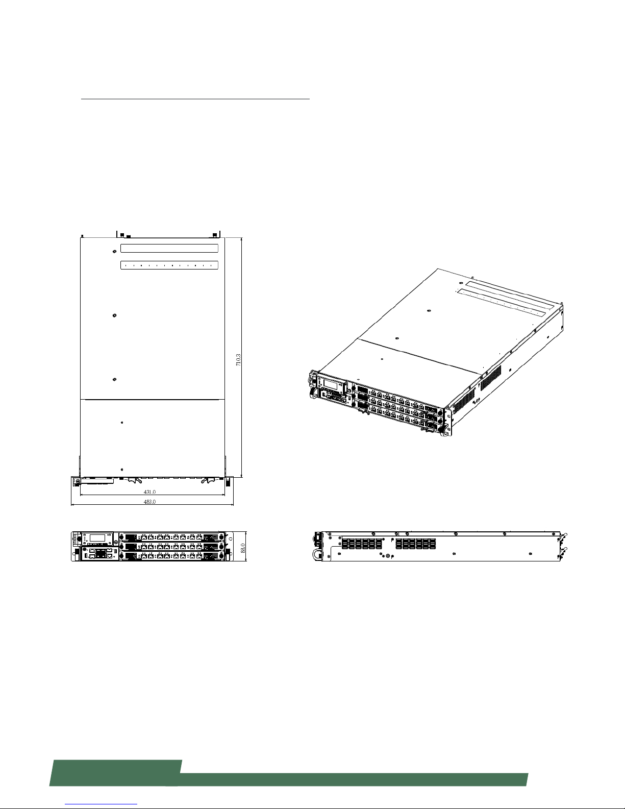
Dimensions W 431 xH 88 x D 720(mm)
Certication RoHS
Page 11

11
www.lannerinc.com
Package Contents
Your package contains the following items:
HCP-72i1 Network Security Platform•
4 passive CPU heatsink•
2 power cords•
2 SATA cables•
1 crossover Ethernet cable (1.8 meters)•
1 straight-through Ethernet cable (1.8 meters)•
1 RJ-45 to DB-9 female console cable•
Drivers and user’s manual CD.•
Ordering Information
HCP-72i1 HybridTCA. High-performance Network
Appliance with 4 x IntelR XeonR E5-2600
series, (Sandy/Ivy-Bridge-EP) processor
+ 2 bays for 2.5” HDD with 3 Ethernet
modules
Optional Accessories
NCM-BPGC01A 12 ports GbE RJ-45, Gen 2 Bypass
NCM-BPGC01B 12 ports GbE RJ-45, Without Bypass
NCM-BPSC01A 12 ports GbE SFP, Without Bypass
NCM-BPX402A 4 ports 10G SFP+, Without Bypass
TCM-IXT801A 8 ports 10G SFP+, Without Bypass
Page 12
12
www.lannerinc.com
Molex
ZD
Conn
Molex
ZD
Conn
Molex
ZD
Conn
DDR3 x 8
DDR3 x 8
Intel Xeon
CPU1
Intel Xeon
CPU0
Patsburg
PCH
Back
plane
LAN Module
Bottom (Slot2)
LAN Module
Top (Slot0)
Intel Xeon
CPU0
(Another MB)
LAN Module
Middle (Slot1)
SATA HDD/SSD
Memory
Bus
Memory
Bus
QPI
DMI
USB
SATA
mSATA
USB2.0
SATA
OPMA
VGA
PCIEC1
PCIe x 8
PCIe x 8
PCIe x 8
I/O Board:
USB
Console
LOM
LAN controller
Cave
Creek
PCIe x 8 (NTB)
PCIe x 8
PCIe x 8
PCIe x 4
USB2.0
PCIe 1x
SPI
PCIe x1
MDI
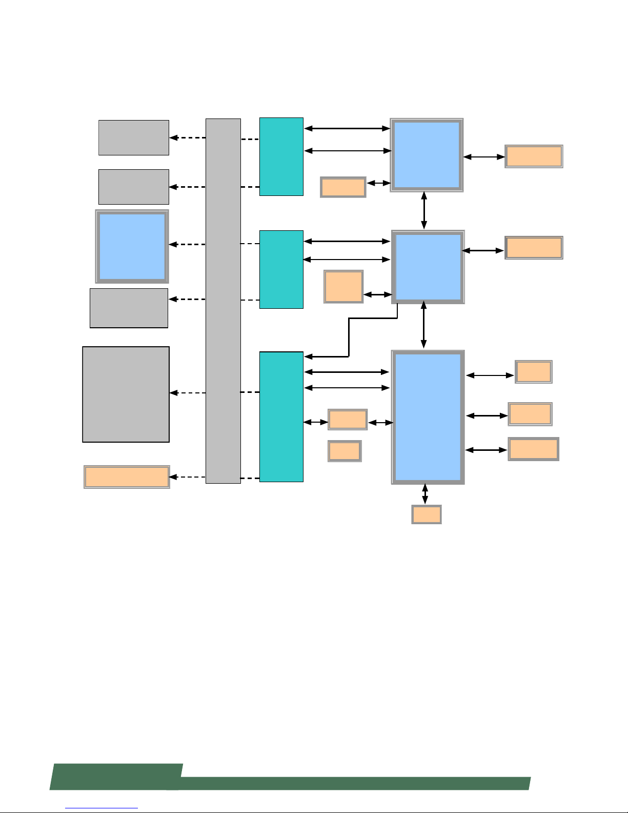
Block Diagram
PCIe
Debug Pin Header
Page 13
13
www.lannerinc.com
Physical Architecture of Lanner’s HybridTCA
The diagram presents all necessary components of Lanner’s Hybrid TCA
architecture applied for HCP-72i1.
Page 14

14
www.lannerinc.com
Chapter 2
System Components
Page 15
15
www.lannerinc.com
Chapter 2:
System Components
Mechanical Drawings
Unit: mm
Page 16
16
www.lannerinc.com
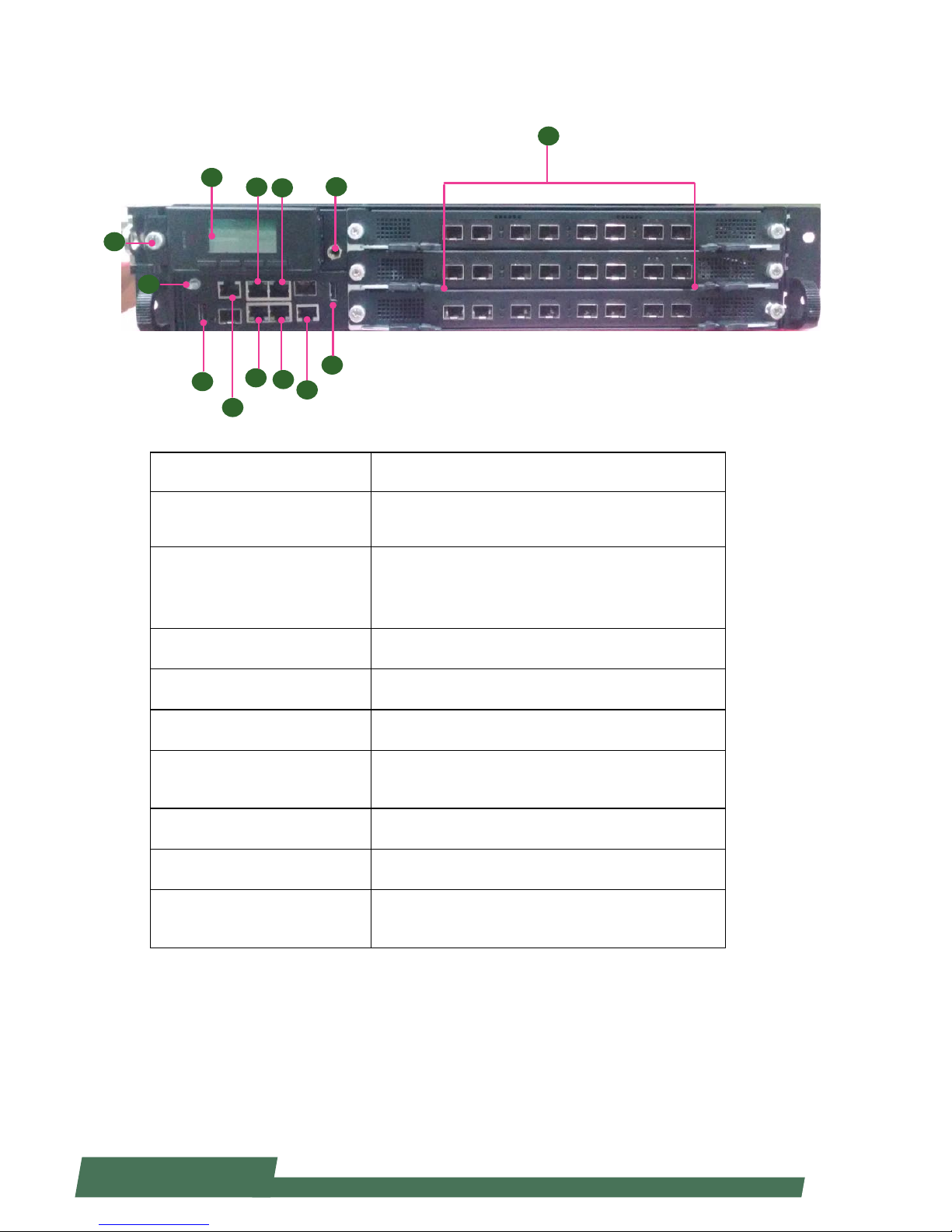
Front Components
Component Description
F1 Console
RJ-45 console port for connecting to a computer terminal
for local, out-of-band diagnostic or configuration
purpose.
F2 LCM
128 x 64 Graph LCM with 4 key pad•
Hinge LCM•
1 LED for power, 1 LED for Status and 1 LED for HDD•
F3 USB 2.0 Ports USB 2.0 type A connectors.
F4 Onboard Management Port RJ-45 onboard management port
F5 IPMI ports IPMI ports
F6 LCM Unlock Button
Push it to unlock LCM pad to access the two 2.5” drive
bays
F7 ESD Jack 1 x ESD Jack
F8 GND Ground
F9 Other RJ-45/SFP+ ports
Network ports (number and type of network ports may
vary depending on the modules installed)
F2
F1
F3
F1
F5
F4
F3
F6
F9
F7
F8
F5
F4
Page 17
17
www.lannerinc.com
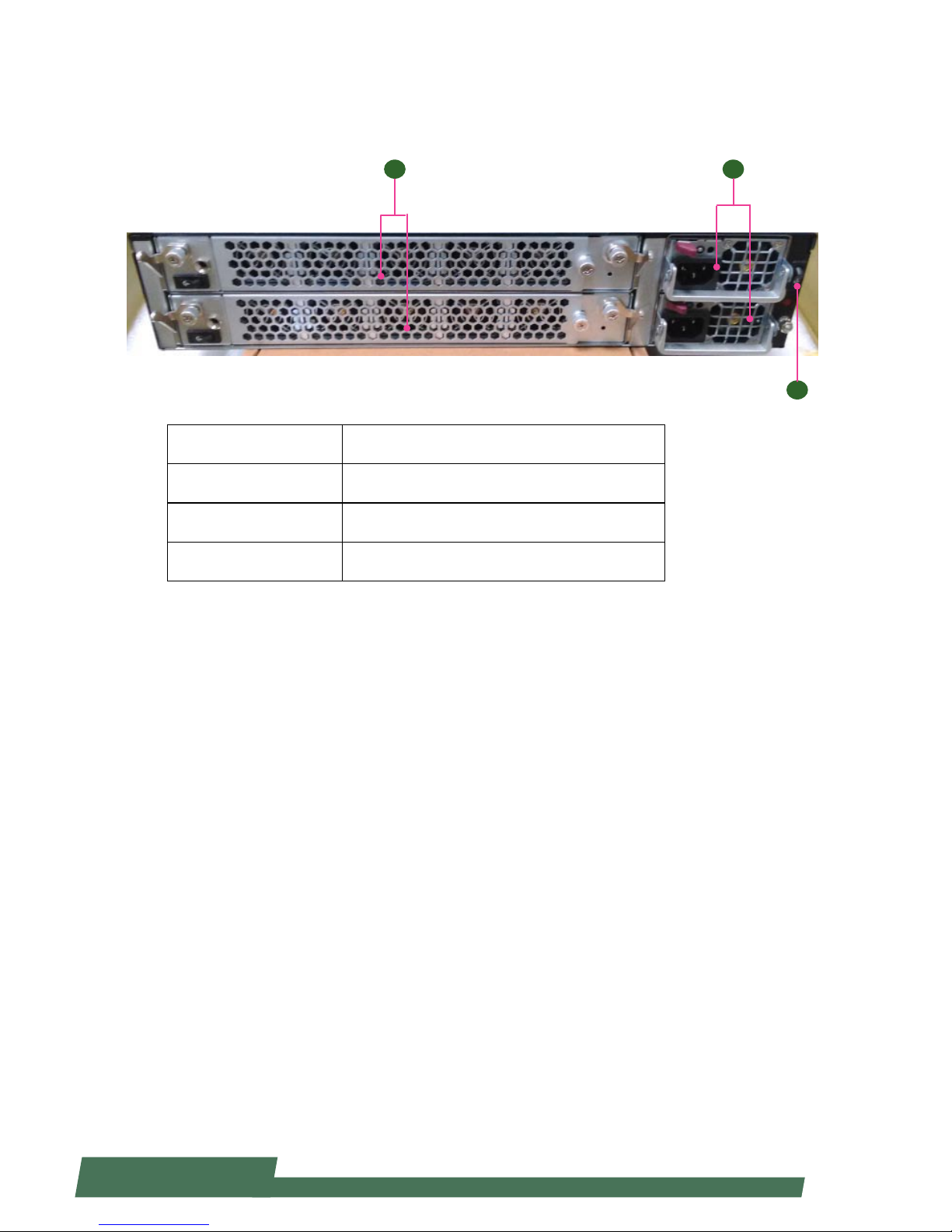
Rear Components
Component Description
R1 Cooling fans 5x cooling fans each layer
R2 Power supply Redundent power supply for each layer
R3 Power Switch Turn on/off of the system
R1 R2
R3
Page 18

18
www.lannerinc.com
Chapter 3
Motherboard Information
Page 19

19
www.lannerinc.com
An Internal Glance of HCP-72i1
The inside of HCP-72i1 is designed based on Lanner’s exclusive HybridTCA structure. This hybrid design integrates
two identical, high-performance motherboards for optimal system boost.
Chapter 3:
Motherboard Information
Upper Board
Bottom Board
Page 20
20
www.lannerinc.com
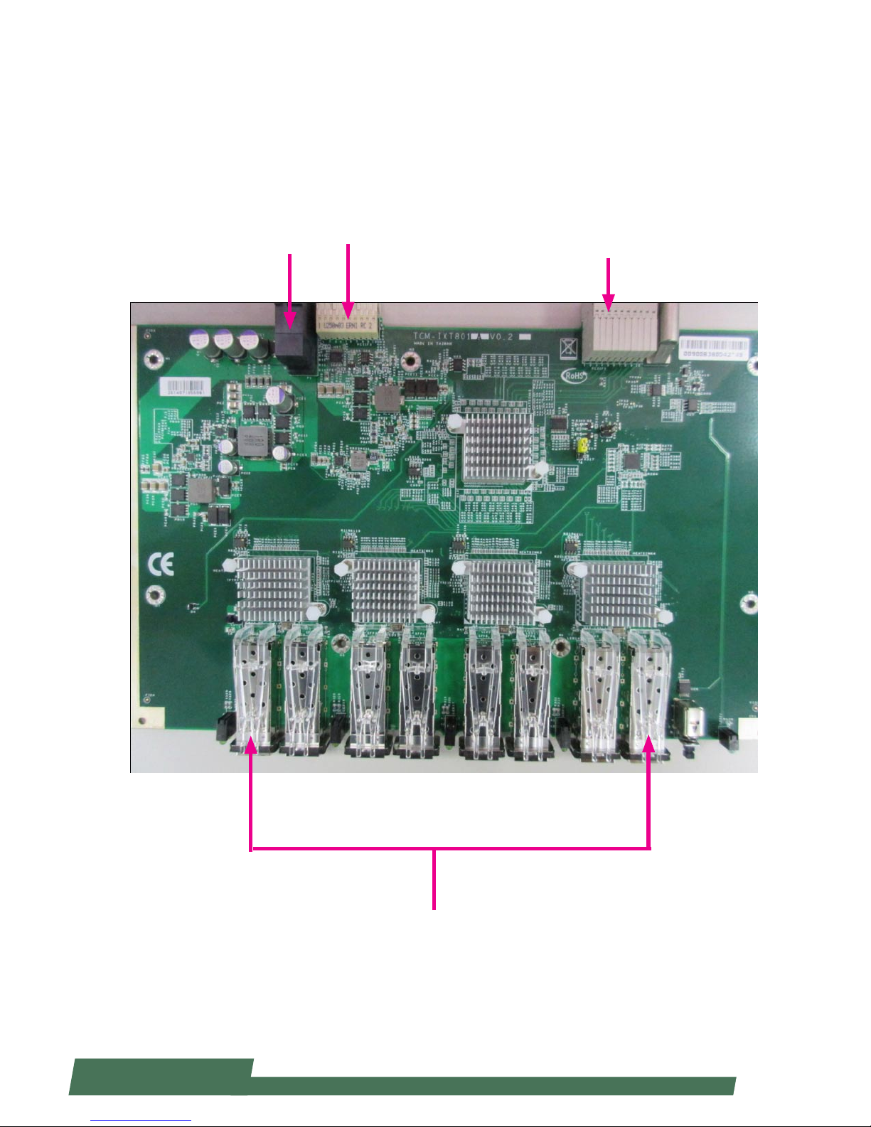
An Internal Glance of HCP-72i1
HCP-72i1 can be connected with up to 3 LAN modules for networking applications. The image below shows the
LAN module “TCM-IXT801A”.
SFP+ 10G ports
Power
PCIe Hot-Swap
PCIe
Page 21
21
www.lannerinc.com
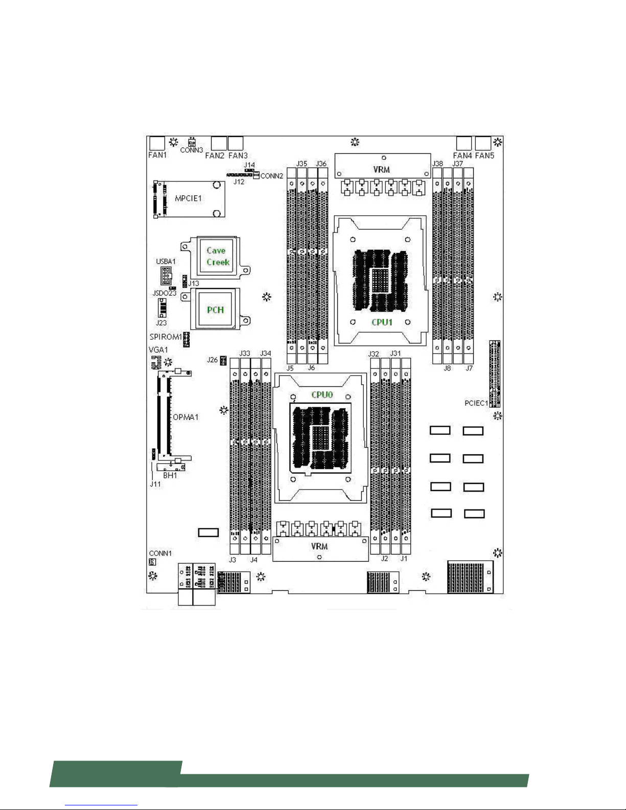
Jumper and Connector Location
The illustration below presents the jumper and
connector location of each board.
Page 22

22
www.lannerinc.com
Connectors and Jumpers List
The tables below list the jumper and connector label of each board.
Labels Function
FAN1~5 FAN connectors
J14 Front Panel Reset Button Setting
CONN2 Power-On Button Pin Header
J12 CPLD Flash Pin Header
MPCIE1 Mini PCIe Socket
USBA1 USB connector
JSDO23 Security Override
J13 LPC Port 80
SPIROM1 SPI Flash ROM Update Pin Header
J23 SATA Connector
J26 SATA Re-driver Value Flash Pin Header
J11 CMOS clear
VGA1 VGA connector
CONN3 Hot Swap LED Pin Header
CONN1 Hot Swap MRL (Manual Retention Latch) Pin Header
Page 23
23
www.lannerinc.com
Jumper Settings & Connectors Pin
Definitions
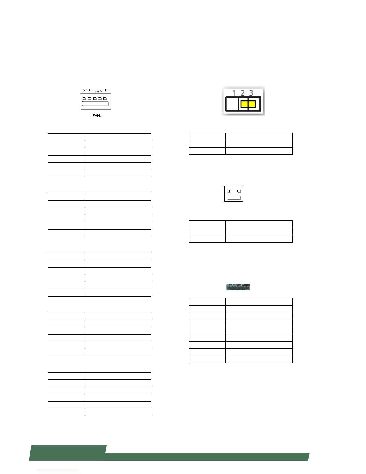
FAN connectors (FAN1~5):
Five-pin FAN connectors
FAN1
Pin Description
1 HM_PWMOUT1
2 FAN_TECH_IN_FAN1
3 FAN_TECH_IN_FAN2
4 12V
5 GND
FAN2
Pin Description
1 HM_PWMOUT2
2 FAN_TECH_IN_FAN7
3 FAN_TECH_IN_FAN8
4 12V
5 GND
FAN3
Pin Description
1 HM_PWMOUT1
2 FAN_TECH_IN_FAN3
3 FAN_TECH_IN_FAN4
4 12V
5 GND
FAN4
Pin Description
1 HM_PWMOUT2
2 FAN_TECH_IN_FAN9
3 FAN_TECH_IN_FAN10
4 12V
5 GND
FAN5
Pin Description
1 HM_PWMOUT3
2 FAN_TECH_IN_FAN5
3 FAN_TECH_IN_FAN6
4 12V
5 GND
Front Panel Reset Button Setting(J14)
The jumper setting for selecting hardware reset or
software reset. Software reset is the default option.
Pin Description
1-2 Hardware reset
2-3 Software reset (default)
Power-On Button (CONN2)
Pin Description
1 GND
2 PWR_BUTTON
CPLD Flash Pin Header (J12):
Complex Programmable Logic Device can be used to
bridge JTAG and ash memory data interface
Pin Description
1 3.3V standby
2 JIAG_PLD_TDO
3 JTAG_PLD_TDI
4 NC
5 NC
6 JTAG_PLD_TMS
7 GND
8 JTAG_PLD_TCK
CONN2
1
2
Page 24
24
www.lannerinc.com
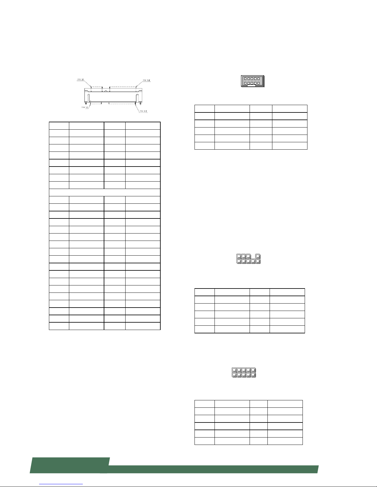
Mini-PCIe socket (MPCIE1):
Serves as mSATA storage socket
Pin Description Pin Description
1 NC 2 3.3V
3 NC 4 GND
5 NC 6 NC
7 NC 8 NC
9 GND 10 NC
11 PCIe Clock_N 12 NC
13 PCIe Clock_P 14 NC
15 GND 16 NC
Mechanical key
17 NC 18 3.3V
19 NC 20 NC
21 GND 22 PCIe Reset#
23 SATA_RX_N 24 3.3V
25 SATA_RX_P 26 GND
27 GND 28 NC
29 GND 30 NC
31 SATA_TX_N 32 NC
33 SATA_TX_P 34 GND
35 GND 36 NC
37 GND 38 NC
39 3.3V 40 GND
41 3.3V 42 NC
43 GND 44 NC
45 NC 46 NC
47 NC 48 NC
49 Active#/LED 50 GND
51 NC 52 3.3V
USB connector (USBA1)
Pin Description Pin Description
1 5V 2 5V
3 USB2- 4 USB35 USB2+ 6 USB3+
7 USB23GND 8 USB23GND
9 USB23GND 10 USB23GND
Security Override (JSDO23)
FLASH DESCRIPTOR SECURITY OVERRIDE WHEN HIGH
(Default Not Connect)
Port 80 (J13): This is the Port 80h, which is used as
BIOS debug port. Once the system is initialized, BIOS
will send POST (Power-On Self-Test) codes to Port 80.
If POST fails, the last generated POST code will be left
in Port 80. This is used for debug purpose. If a sevensegment display is connected, the hexadecimal BIOS
debug code will appear.
Pin Description Pin Description
1 CLK_33M_P80 2 LPC_LAD_1
3 RST_PORT80_N 4 LPC_LAD_0
5 LPC_FRAME_N 6 3.3V
7 LPC_LAD_3 8 X
9 LPC_LAD_2 10 GND
SPIROM1:
SPI ROM pin header
Pin Description Pin Description
1 No Connect 2 No Connect
3 Dual_CS00_N 4 3.3V
5 SPI_MISO_DUAL 6 SPI_HOLD0_L
7 No Connect 8 SPI_CLK_DUAL
9 GND 10 SPI_MOSI_DUAL
1 2 9
10
USBA1
J13
9
10
2
1
SPI-ROM1
9
10
2
1
Page 25
25
www.lannerinc.com
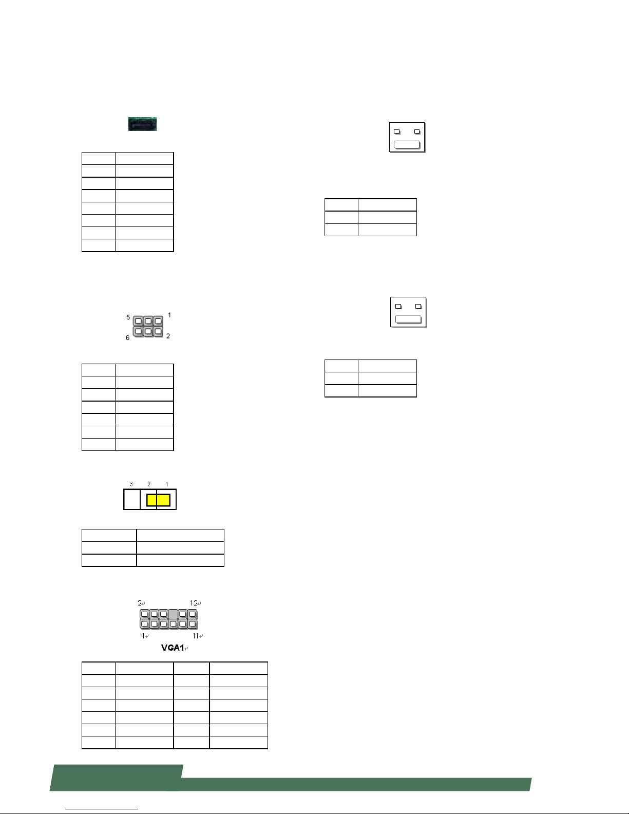
SATA (J23): used to connect SATA disk drive
Pin Description
1 GND
2 TX+
3 TX4 GND
5 RX6 RX+
7 GND
SATA Re-Driver value flash (J26)
SATA signal redriver and conditioner
Pin Description
1 PCIE_R_SDA2
2 3.3V
3 PCIE_R_SCL2
4 MOSI2
5 REST_MCU2#
6 GND
CMOS clear (J11): clear CMOS jumper
Pin Description
Short 1-2 (default) Normal
Short 2-3 Clear CMOS
VGA connector (VGA1): VGA display
Pin Description Pin Description
1 RED 2 GND
3 GREEN 4 GND
5 BLUE 6 GND
7 HSYNC 8 X
9 VSYNC 10 GND
11 DDC_DATA_CONT 12 DDC_CLK_CONT
Hot swap LED(CONN3)
Pin Description
1 LED_P
2 LED_N
Hot swap MRL(Manual Retention Latch) pin
header(CONN1)
Pin Description
1 Power Enable#
2 GND
CONN3
1
2
CONN1
1
2
Page 26

26
www.lannerinc.com
Chapter 4
Hardware Installation
Page 27
27
www.lannerinc.com
Chapter 4:
Hardware Installation
Preparing the Hardware Installation
To access some components and perform certain service
procedures, you must perform the following procedures
first.
WARNING:
1. To avoid the risk of personal injury, electric shock, or
damage to the equipment, please remove all power
connections as well as all power sources.
2. Please wear ESD gloves to avoid potential injury or
damage.
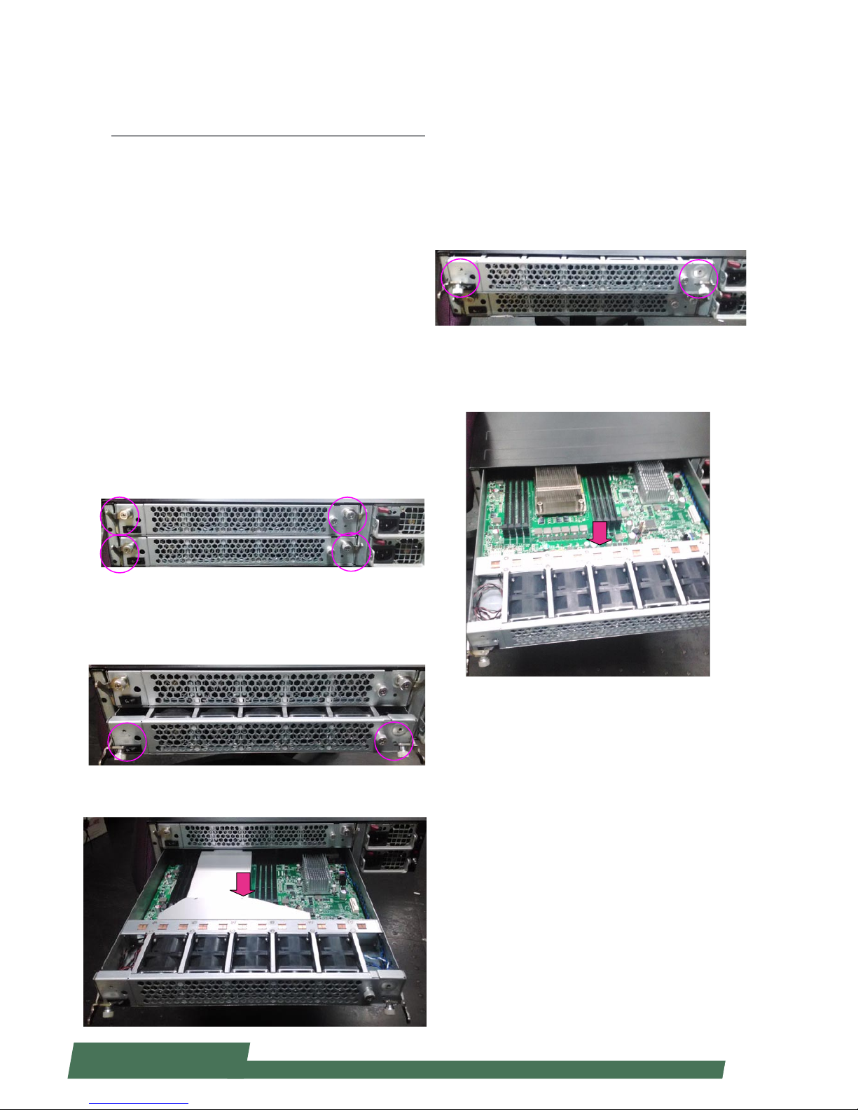
Accessing the Components
1. Due to the hybrid architecture of HCP-72i1, you may
access the Upper Board or the Bottom Board. First, locate
the rear lock-handles and lock-screws. There should be 2
pairs on each side: two for the Upper Board and the other
two for the Bottom Board.
2. To access the Bottom Board, loosen the two lockscrews and then pull the two lock-handles.
3. Pull the blade out while holding the lock-handles.
4. To return the bottom blade to its original place, simply
push it to the end and use the two lock-handles and lockscrews to secure it.
5. To access the Upper Board, use the same method from
Step 2 and 3.
6. Pull the top blade out while holding the lock-handles.
Page 28
28
www.lannerinc.com
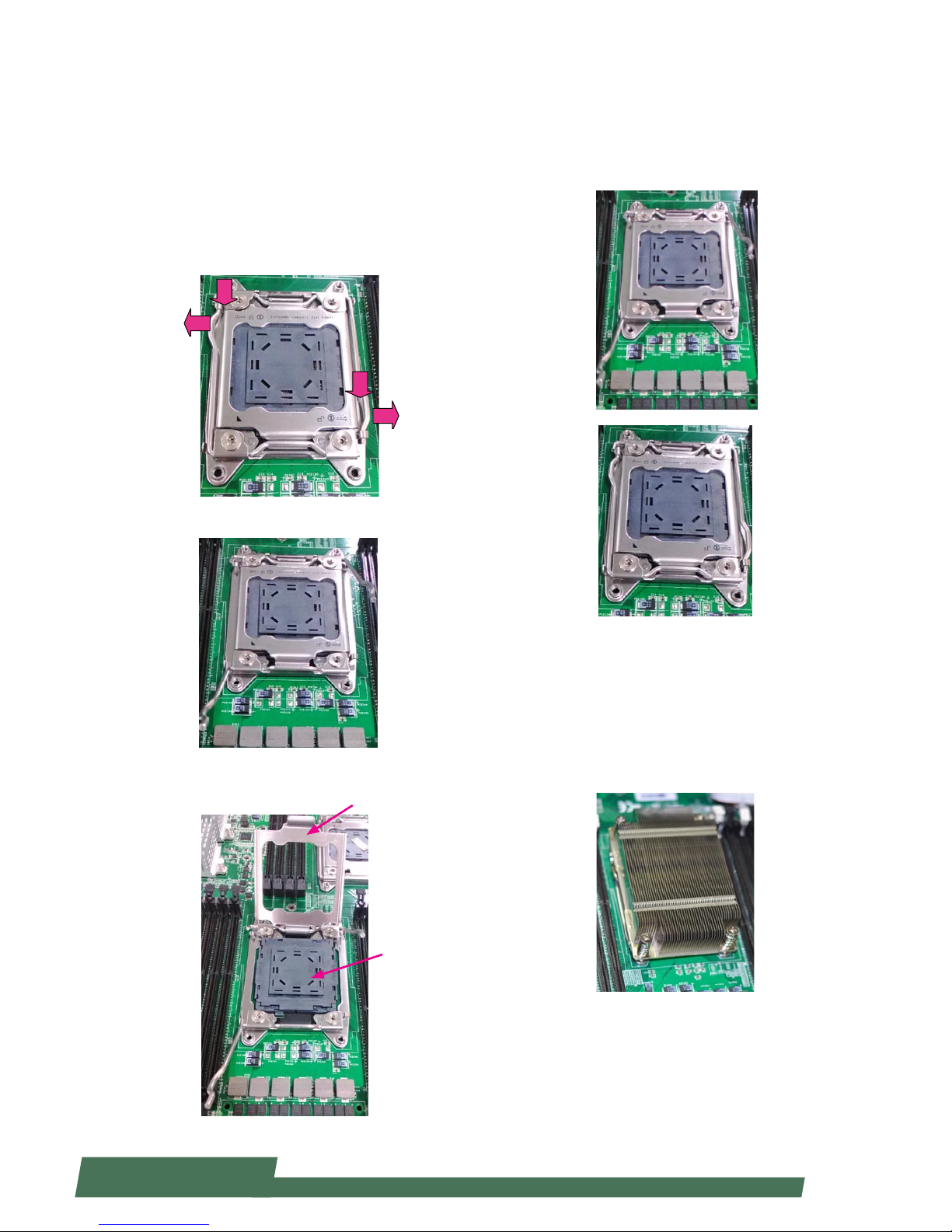
Installing CPU and the Heat Sink
Follow the procedures below for installing a CPU
1. Locate the CPU socket(s)
2. Press the left load lever down, move it out of the
retention tab. Then, do the same to the right. There are
two levers for each CPU socket.
3. Lift the load levers.
4. Open the load plate and also the protective cap.
Press down
Press down
Load plate
Protective cap
5. Align the CPU and the notch on the socket. The CPU should
fit perfectly into the socket. Note that the CPU fits in the
socket in only one direction.
6. Put the protective cap onto the CPU. Close the load plate
and push the load lever to lock it back to the retention tab.
7. Put the heat sink on the installed CPU and match the
screws with the screw holes on the board. Fasten two screws
which are opposite to each other at a time and then the other
two. It is easier this way to avoid the force of spring.
Place the heat sink cover on top of the installed heat sink and
fasten it with screws on the chassis.
Page 29
29
www.lannerinc.com
Installing IPMI Card on OPMA Socket
The motherboard of HCP-72I1 comes with a OPMA
socket for IPMI card installation.
1. Locate the OPMA socket.
2. Insert your IPMI card. Make sure the notches
between the card and the socket are aligned.
3. Your IPMI card may come with a display connector.
You may use a cable for connections.
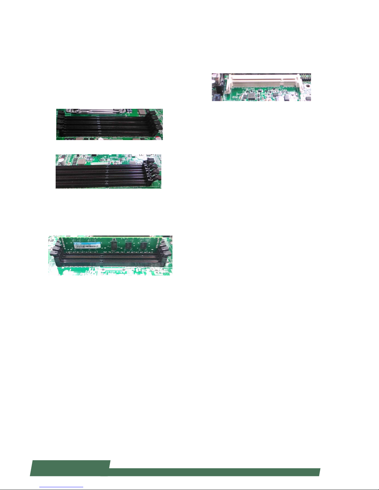
Installing the System Memory
The motherboard supports DDR3 memory to meet the
higher bandwidth requirement of the latest operating
system and Internet applications. It comes with two
double data rate type three (DDR3) Small Outline Dual
Inline Memory Modules (SO-DIMM) sockets.
1. Power o the system
2. Locate the DIMM socket
3. Pull open the latches
4. Align the module and the socket and then insert
the module into the socket. Make sure the notches
are aligned. Press the module until it's fully seated and
close the latches.
Page 30
30
www.lannerinc.com
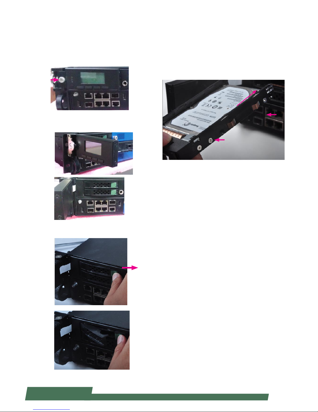
Installing HDD/SSD
The system is built to accommodate two 2.5” SATA disk
drives. Please follow instructions below.
1. The two 2.5” SATA disk drives are located behind the
hinge LCM. Rotate and loosen the lock-screw.
2. Open the hinge LCM and locate the HDD/SSD bays as
the images shown below.
3. Push the disk drive lock as the arrow of direction in the
image below. Then the disk drive bay will be released out.
4. Insert your HDD/SSD into the bay by aiming the SATA
connector of the drive as the arrow of direction in the
image shown below. Remember to use screws to fix both
sides of the disk drives.
SATA Connector direction
Page 31

31
www.lannerinc.com
Replacing Network I/O Modules
Please follow the instructions below to replace network
I/O modules. The images of network I/O modules below
are based on Lanner TCM-IXT801A model.
1. Loosen the lock-screw on two sides of the network I/O
module.
2. Hold and press the lock-handle as the arrow of direction in the image below. Remember to do it for both lockhandles at the same time.
3. While pressing both lock-handles as instructed in the
last step, then pull both lock-handles outwards at the
same time.
4. Continue to apply force when removing the module.
To install a module, just reverse the steps in this section.
Replacing Power Supply Units
Power supply units may have to be replaced when
they reach the end of their liftetime. Please follow the
instructions below to replace power supply units.
1. Locate the power supply units at the rear. Hold the
handle and press the lock as the arrow of direction in the
image below.
2. Pull the power supply unit out.
Page 32

32
www.lannerinc.com
Replacing Cooling Fans
Cooling fans may have to be replaced as they may reach
the end of their lifetime one day. Please follow the
instructions below to replace cooling fans.
1. Loosen the lock-screw on the cover of the cooling fans
array.
2. Slide the cover to the arrow of direction as shown in
the image below.
3. Apply forces onto the two clips and pull the fan out.
Page 33

33
www.lannerinc.com
3. Turn the slide rail upside down and push the black
arrow-shaped slide rail lock as the arrow of direction
below.
4. Press the security lock of the rail as well.
5. Separate the inner bracket from the slide rail.
6. Align the inner bracket to the side of the chassis.
Make sure the screw holes of the inner bracket match
with the ones on the side of the chassis.
7. Securely attach the inner bracket to the side of the
chassis by applying screws.
8. Repeat step 1 to 7 for another slide rail and for the
other side of the chassis.
Rack Mounting
Installation Precautions:
Elevated Operating Ambient - If installed in a closed 1.
or multi-unit rack assembly, the operating ambient
temperature of the rack environment may be greater
than room ambient. Therefore, consideration should be
given to installing the equipment in an environment
compatible with the maximum ambient temperature
(Tma) specified by the manufacturer.
Reduced Air Flow - Installation of the equipment in 2.
a rack should be such that the amount of air flow
required for safe operation of the equipment is not
compromised. Mechanical Loading - Mounting of the
equipment in the rack should be such that a hazardous
condition is not created due to uneven mechanical
loading.
Circuit Overloading - Consideration should be given to 3.
the connection of the equipment to the supply circuit
and the effect that overloading of the circuits might
have on over-current protection and supply wiring.
Appropriate consideration of equipment nameplate
ratings should be used when addressing this concern.
Reliable Earthing - Reliable earthing of rack-mounted 4.
equipment should be maintained. Particular attention
should be given to supply connections other than
direct connections to the branch circuit (e.g. use of
power strips).”
CAUTION :
Slide/rail mounted equipment is not to be used as a
shelf or a work space.
Prepare The Equipments
1. Prepare the slide rail equipments. In the package, you
should have two slide rails and 1 bag of screws.
2. Extend the inner bracket of each slide rail.
Page 34

34
www.lannerinc.com
Installing Slide Rails Onto the Rack
1. Install 2 cage nuts for both left and right of the rack,
as well as front and rear of the rack. Remember to leave
the middle hole open. You shall install a total number
of 8 cage nuts: 4 on the front (2 for the left and 2 for
the right), and 4 on the rear (2 for the left and 2 for the
right).
2. Install the slide rails to each side of the racket as the
image below. Make sure the screws are firmly applied.
Installing HCP-72i1 Onto the Rack
1. Inser the network appiance with the front facing
you. Make sure the chassis-attahced inner brackets accurately match the slide rails installed on the rack.
Notes: it is strongly recommended to conduct this action with two or more persons.
2. Make sure the inner brackets on the chassis match the
slide rails on the rack.
3. Gently push HCP-72i1 through the rails.
4. The device may be locked during the mid way. Remember to adjust the rail lock so that you can continue to psuh
the appliance to the end of the rack.
5. To bring the appliance out of the rack, use the two locks
on the rail circled in the image below. When sliding the
device out, remember to do it slowly.
Notes: it is strongly recommended to conduct this action
with two or more persons.
Page 35

35
www.lannerinc.com
Chapter 5
BIOS Setup
Page 36

36
www.lannerinc.com
Chapter 5:
BIOS Setup
To enter the BIOS setup utility, simply follow the steps below:
1. Boot up the system.
2. Press <Delete> during the boot-up if you connect a keyboard to HCP-72i1. But if you connect a PC to HCP-72i1
through console cable, then press <Tab>. Your system should be running POST (Power-On-Self-Test) upon booting
up.
About the POST Information of HCP-72i1:
HCP-72i1 is built based on HTCA structure with two motherboards. You may access either or both of the boards
depending on the connections established. You will see messages of whether you access the “Upper Board” or the
“Bottom Board” during the booting-up process.
3. Then you will be directed to the BIOS main screen.
4. Instructions of BIOS navigations:
[<--] [-->]: select a setup screen, for instance, [Main], [Advanced], [Chipset], [Boot], [Security], and
[Save & Exit]
[↑] [↓]: select an item/option on a setup screen
Enter: select an item/option or enter a sub-menu
ESC: exit the current screen
+/- = to adjust values for the selected setup item/option
F1 = to display General Help screen
F2 = to retrieve previous values, such as the parameters configured the last time you had entered BIOS.
F3 = to load optimized default values
F4 = to save configurations and exit BIOS
Notes: the images in the following section are for reference only.
Page 37

37
www.lannerinc.com
Main
The [Main] is the first setup screen when you enter BIOS. The [Main] displays general system and BIOS information
and you may configure the “System Language”, “System Date”, and “System Time”.
BIOS Information
BIOS Vendor: displays BIOS vendor information
Core Version: displays the BIOS core version
Compliancy: displays the BIOS compliancy
Project Version: displays BIOS project version
Build Date and Time: displays the date and time the BIOS was built.
Press “Enter” if you want to configure “System Language”, “System Date”, and “System Time”.
System Language: English
System Date: Day/Date/Year
System time: Hour/Minutes/Seconds
Access Level: Administrator by default
Page 38

38
www.lannerinc.com
Advanced
Use [<--] / [-->] to select [Advanced] setup screen. Under this screen, you may use [↑] [↓] to select an item you
want to configure.
Above 4G Decoding
This option enables or disables 64bit capable devices to be decoded in above 4G address space (only if the
system supports 64bit PCI decoding). You may select “Enabled” or “Disabled”.
Page 39

39
www.lannerinc.com
SRIOV
This option enables or disables SRIOV (Single Root I/O Virtualization) support. You may select “Enable” or “Disable”.
Set Pcie Driving By B
This option enables or disables PCIe driving by BIOS. You may select “Enabled” or “Disabled”.
Page 40

40
www.lannerinc.com
WHEA Configuration
This option allows you to conduct general WHEA (Windows Hardware Error Architecture) Configuration settings.
Press “Enter” to enter its setting menu.
Then you may select “Enabled” or “Disabled for WHEA support. The default is “Enabled”.
Page 41

41
www.lannerinc.com
CPU Configuration
This option allows you to access CPU configuration parameters. To access the sub menu, press “Enter” to access the
configuration parameters.
Socket 0/1 CPU Information - press “Enter” to display CPU0 information including CPU model name, signature,
microcode patch, maximum CPU speed, minimum CPU speed, processor cores, Intel HT Technology, Intel VT-x
Technology, L1 data cache, L1 code cache and L2/L3 cache.
Page 42

42
www.lannerinc.com
Hyper-threading: Hyper-threading is Intel’s multi-threading technology which improves computer multi-tasking
ability. This is frequently abbreviated as Intel® HT Technology. This enhancement design enables multiple threads to
run on each processor core. As a result, this will boost performance and throughput.
Active Processor Core: set the number of active processor cores.
Limit CPUID Maximum: When “Enabled”, the CPU will limit its maximum CPUID input value to 3 when the processor
is queried. When “Disabled”, the CPU will function with its actual maximum CPUID values. For this case, leave it as
“Disabled”.
Page 43

43
www.lannerinc.com
Execute Disable Bit: an Intel hardware-based protection against malicious code. It will detect the memory in which a
code can be executed or not. When enabled, it will prevent certain classes of malicious buffer overflow attacks when
combined with a supporting OS.
Hardware Prefetcher: when “Enabled”, it will activate the mid level cache L2 streamer prefetcher.
Adjacent Cache Line P: it is the Adjacent Cache-Line Prefetch. When “Enabled”, the CPU fetches Cache 1 & 2 for 128
bytes. If “Disabled”, the CPU only fetches one cache for just 64 byte. The default is “Enabled”.
Page 44

44
www.lannerinc.com
DCU Streamer Prefetch: When “Enabled”, it will activate the prefetch of next L1 Data Line based upon multiple loads
in same cache line.
DCU IP Prefetch: this allows you to enable prefetch of next L1 line based upon sequential load history.
Intel Virtualization: Enables or disables Intel Virtualization Technology. On a server or firewall/UTM/IPS operating mode,
it is recommended to enable this feature so that multiple operating systems and applications will run in independent
partitions.
Page 45

45
www.lannerinc.com
Local APIC Mode: select local APIC mode. If “Auto”, use x2APIC if required; otherwise, xAPIC mode. The xAPIC mode
will disable CPUs with APIC IDs greater than 254. Please be aware that some operating systems don’t support x2APIC
mode.
EIST: this option allows you to enable/disable Intel SpeedStep Technology.
Page 46

46
www.lannerinc.com
SATA Configuration
This option allows you to access SATA device configuration. Press “Enter” to access the sub-menu.
SATA Port 0 - 5: display SATA device information. If no device detected, it will show “Not Present”.
SATA Mode: select “IDE”, “AHCI”, or “RAID” mode for connected SATA storage devices. For RAID mode, your system
must be pre-programmed with RAID mode support.
Page 47

47
www.lannerinc.com
Aggressive Link Power: Aggressive Link Power Management for SATA devices complying with AHCI mode.
Port 0-5 Hot Plug: enable SATA hot plug for port 0-5.
Page 48

48
www.lannerinc.com
USB Configuration
This option allows you to access USB configuration parameters. Press “Enter” to access the sub-menu.
USB Module Version: displays USB module version information
USB Devices: displays USB device information
Legacy USB Support: enables legacy USB support. “Auto” option disables legacy support if no USB devices are
connected. “Disable” option will keep USB devices available only for EFT applications.
Page 49

49
www.lannerinc.com
EHCI Hand-off: this is a workaround for operating systems without EHCI hand-off support. The EHCI ownership
change should be claimed by EHCI driver.
USB Mass Storage Driv: this option allows you to enable or disable USB mass storage driver. The default is
“Enabled”.
Page 50

50
www.lannerinc.com
USB transfer time-out: set USB time-out value for control, Bulk and interrupt transfers.
Device reset time-out: set USB mass storage device Start Unit command time-out.
Device power-up delay: set the maximum time the device will take before it properly reports itself to the Host
Controller. “Auto” uses default value. For example, it is 100ms as a root port.
Page 51

51
www.lannerinc.com
Hardware Monitor
This option allows you to monitor hardware status. Press “Enter” to access the sub-menu.
Smart Fan Configuration: access smart fan parameters
CPU0/1 Temp: CPU(s) temperature
System Temp1/2: temperatures of system 1/2
FanXX Speed: the speed of each fan based on RPM
CPU0/1 Vcore: dispalys voltage information of CPU cores
Page 52

52
www.lannerinc.com
LAN Module Hardware Monitor
This option allows you to monitor hardware status of connected LAN modules. Press “Enter” to access the submenu.
Once entered, you may view PCIe layer information for the connected LAN modules.
Page 53

53
www.lannerinc.com
LAN Boot Select
This option allows you to select one of the onboard LAN PXE boot. Press “Enter” to access the sub-menu.
On Board LAN Boot: the default is “Enable”
Page 54

54
www.lannerinc.com
Serial Port Console Redirection
This option allows you to configure parameters about serial port console redirection. Press “Enter” to access the submenu.
Console Redirection: select “Enabled” or “Disable” for COM port console redirection. The default is “Enabled”.
Console Redirection Settings: select this item to enter the setting sub-menu.
Page 55

55
www.lannerinc.com
COM Console Redirection Settings
Terminal Type: the emulation configuration. Select “VT100”, “VT100+”, “VT-UTF8” or “ANSI”.
ANSI: Extended ASCII character set
VT100: ASCII character set
VT100+: extends VT100 to support color function keys
VT-UTF8: uses UTF8 encoding to map Unicode characters onto 1 or more
Bits per second: select “9600”, “19700”, “38400”, “57600”, or “115200” for bits per second. The Bps
will determine serial port transmision speed. The speed must be matched on the other side. Long or noisy lines may
require lower speeds.
Page 56

56
www.lannerinc.com
Data Bits: select the value for data bits. In this case, “7” or “8”.
Parity Bits: a parity bit can be sent with the data bits to detect some transmission errors. Select “None”, “Even”, “Odd”,
“Mark” or “Space”.
Page 57

57
www.lannerinc.com
Stop Bits: stop bits indicate the end of a serial data packet. The standard is 1 stop bit. Communication with slow
devices may require more than 1.
Flow Control: flow control can prevent data loss from buffer overflow. When sending data, if the receiving buffers
are full, a “stop” signal can be sent to stop the data flow. You may select “None” or “Hardware RTS/CTS”, depending on
the circumstances.
Page 58

58
www.lannerinc.com
VT-UTF8 Combo Key Support: this option enables/disables VT-UTF8 combination key support for ANSI/VT100
terminals.
Recorder Mode: on this mode, when “Enabled”, only text will be sent. This is to capture terminal data.
Resolution 100 x 31: select “Enable” or “Disable” for extended terminal resolution.
Page 59

59
www.lannerinc.com
Legacy OS Redirection Resolution: select “80x24” or “80x25”. The default for this case is “80x24”.
Putty KeyPad: select Function Key and Key Pad on Putty. You may select “VT100”, “LINUX”, “XTERMR6”, “SC0”, “ESCN”,
or “V1400”.
Redirection After BIOS POST: The settings specify if BootLoader is selected than Legacy console redirection is
disabled before booting to Legacy OS. Default value is “Always Enable” which means Legacy OS console redirection
is always enabled after BIOS.
Page 60

60
www.lannerinc.com
Chipset
Use [<--] / [-->] to select [Chipset] setup screen. Under this screen, you may use [↑] [↓] to select an item you
want to configure.
Restore AC Power Loss: This option specifies what state to go to when power is re-applied after a power failure (G3
state). You may select “Power Off”, “Power On” or “Last State”. The default is “Power On”.
Onboard SATA RAID Oprom/Driver: controls whether to enable the onboard SATA Option ROM or EFI Driver.
Page 61

61
www.lannerinc.com
IOH Configuration
Intel(R) NTB Configuration: press “Enter” to access the sub-menu for Intel Non-Transparent Bridge (NTB)
configurations.
Then, you may select “TB”, “NTB-NTR” or “NTB-RP” for the NTB configuration. Remember to set different NTB ports for
“Crosslink Control” for the Upper Board and the Bottom Board. For instance, as the image below, the crosslink control
is DSD/USP for the Upper Board while setting “USD/USP for the Bottom Board.
Page 62

62
www.lannerinc.com
Intel (R) VT for Directed I/O Configuration
This option is enabled by Intel’s virtualization technology. Press “Enter” to access the sub-menu.
Intel (R) VT-d: this option allows you to enable or disable Intel Virtualization Technology fo directed I/O. The default
is “Enabled” as this enhances server/firewall performance.
Page 63

63
www.lannerinc.com
Coherency Support: enable it to enhance operational coherency, but might lower system performance. Therefore,
this option is left as “Disabled” by default.
ATS Support: Address Translation Services. This function is enabled if “Intel(R) VT-d” is activated by default setting.
Enabling it will improve DMA performance.
Page 64

64
www.lannerinc.com
Intel (R) I/OAT:This option is enabled by Intel’s virtualization technology. Press “Enter” to access the sub-menu.
This is the Intel I/O Acceleration Technology option. Enable it to accelerate system performance in virtualization
operation. However, for considerations regarding possible data loss under Linux operating systems, this is “Disabled”
by default.
IOH Resource Selection: you may select “Auto” or “Manual” for your I/O hub (IOH) resource allocation. If you select
“Auto”, PCI resource allocation across multiple IOHs is optimized automatically based on the PCI devices present.
Therefore, the default is set as “Auto” instead of “Manual”.
Page 65

65
www.lannerinc.com
No Snoop Optimization: this option allows you to enable or disable Intel Virtualization Technology fo directed I/O.
The default is “Enabled” as this enhances server/firewall performance. This configuration requires that no snoop in PCI
Express settings is enabled. It is recommended that this option is left at default, which is “VC1”.
MMIOH Size:Configure the capacity size for memory-mapped I/O hub (MMIOH), from 1G to 128G.
Page 66

66
www.lannerinc.com
MMCFG BASE: select MMCFG Base values.
IOH PCIe port Bifurcation Control
IOU1-PCIe Port: functions visible based on these two options: “x4x4” (Function 0/1 visible) or “x8” (Function 1
visible)
Page 67

67
www.lannerinc.com
Port 1A/1B/2A Link Speed: select “GEN1”, “GEN2” or “GEN3” for the target link speed.
IOU2-PCIe Port: Functions visible based on the following options:
x4x4x4x4: functions 0/1/2/3 visible
x4x4x8: functions 0/2/3 visible
x8x4x4: functions 0/1/2 visible
x8x8: functions 0/2 visible
x16: function 0 visible
Page 68

68
www.lannerinc.com
Boot
Use [<--] / [-->] to select [Boot] setup screen. Under this screen, you may use [↑] [↓] to select an item you
want to configure.
Boot Configuration
Setup Prompt Timeout: number of seconds to wait for setup activation key. “65535 (0xFFFF)” means indefinite
waitings.
Bootup Numlock State: select the keyboard “Numlock” state
Page 69

69
www.lannerinc.com
Quiet Boot: this option allows you to enable or disable “Quiet Boot”. The default is “Disabled” based on Intel’s server
environment setting.
Fast Boot: select “Enabled” or “Disabled” for fast boot-up process. The default is “Disabled” based on Intel’s server
environment setting.
Set Boot Priority: the following allows you to configure the system boot sequence.
Page 70

70
www.lannerinc.com
CSM16 Parameters:
CSM16 Module Version
GateA20 Active: select “Upon Request” or “Always”.
Upon Request -- GA20 can be disabled using BIOS services.
Always -- do not allow disabling GA20: this option is useful when any RT code is executed above 1MB
Option ROM Message: select “Force BIOS” or “Keep Current”. This option sets display mode for Option ROM.
Page 71

71
www.lannerinc.com
INT19 Trap Response: Select “Immediate” or “Postponed”. This option sets BIOS reaction on INT19 Trapping by Option
ROM:
Immediate - execute the trap right away
Postponed - execute the trap during legacy boot
CSM Parameters
Launch CSM: this option controls if CSM will be launched
Page 72

72
www.lannerinc.com
Boot Option Filter: Select “UEFI and Legacy”, “Legacy only” or “UEFI only”. This option controls what devices system
can boot to.
Launch PXE OpROM Policy: this option controls the execution of UEFI and Legacy PXE OpROM
Launch Storage OpROM: select “Do not launch”, “UEFI only”, “Legacy only”, “Legacy first” or “UEFI first”. This option
controls the execution of UEFI and legacy storage OpROM.
Page 73

73
www.lannerinc.com
Boot Option Filter: select “Do not launch”, “UEFI only”, “Legacy only”, “Legacy first” or “UEFI first”. This option controls
the execution of UEFT and legacy video OpROM.
Other PCI device ROM: select “UEFI OpROM” or “Legacy OpROM”. For PCI devices other than network, mass storage
or video defines which OpROM to launch.
Page 74

74
www.lannerinc.com
NETWORK Device BBS Priorities
1st Boot: set boot priority
Page 75

75
www.lannerinc.com
Security
Use [<--] / [-->] to select [Security] setup screen. Under this screen, you may use [↑] [↓] to select an item you
want to configure.
Administrator Password: set administrator password. Once set, then this only limits access to Setup and is only
asked for when entering Setup.
User Password: set user password. Once set, then this is a power-on password and must be entered to boot or enter
Setup. In Setup, the user will have Administrator rights.
Page 76

76
www.lannerinc.com
Save & Exit
Use [<--] / [-->] to select [Save & Exit] setup screen. Under this screen, you may use [↑] [↓] to select an item you
want to configure.
Save Changes and Exit: exit system setup after saving the configuration changes
Discard Changes and Exit: exit system setup without saving the configuration changes
Save Changes and Reset: reset the system after saving the configuration changes
Discard Changes and Reset: reset the system without saving the configuration changes
Save Options
Save Changes: save the configuration changes
Discard Changes: discard all the configuration changes
Restore Defaults: restore to factory default setting
Save as User Defaults: save changes as the new user default
Restore User Defaults: restore the user default
Boot Override
Launch EFI Shell from filesystem device: launch Extensive Firmware Interface which will allow you to input Shell
commands
Page 77

77
www.lannerinc.com
Chapter 6
IPMI Navigation
Page 78

78
www.lannerinc.com
Chapter 6:
IPMI Navigation
IPMI, abbreviation of Intelligent Platform Management Interface, offers system administrators to manage and
monitor computing platforms with standardized interface and protocol. Due to its messaging and hardware-based
nature, IPMI works independently from the operating system, so that system administrators are able to remotely
manage and monitor computing platform status.
Lanner’s IPMI provides rich management features that will enable users to remote monitor their host machines,
while configuring control options. These include:
Remote control viewing options•
DNS configuration options•
SSL upload/generate/view options•
Network setting•
Firmware update•
User information management•
The following will provide a simple walkthrough of Lanner’s IPMI interface.
Reminder
The images shown in the following section are based on the latest version available at the time of this writing.
Therefore, the images may or may not look identical to the screens on your computing systems.
The following interface images are based on web browser operation.
Before You Start
Make sure the proper LAN connection to HCP-72i1. •
IPMI card has been properly installed.•
Prepare a desktop or laptop that is connecting to the same network. Start the computer. (Preferrably a laptop).•
Make sure JAVA is installed in the computer you are using.•
IP Configuration
Configure the IP address on the computer you are using. Please input “192.168.0.100:80”.•
Go to “JAVA” program, then go to “Exception Site List” and add a new location “192.168.0.100:80”.•
Getting Started
Open a web browser and input “192.168.0.100:80” to launch IPMI interface.
You will be required to enter “Username” and “Password”. The default username and password are “admin” for both.
Page 79

79
www.lannerinc.com
Dashboard
The “Dashboard” provides an overall information about the stauts of the device and remote server.
Device Information
Device Power Status: the power state of the monitored device
Firmware Revision: firmware revision information
Firmware Build Date: the date that the firmware was built
Network Information
MAC Address: displays MAC address information
V4 Network Mode: the status of V4 network
IPv4 Address: the IP address information
V6 Network Mode: the status of V6 network
Remote Control
Click the “Lanuch” bar to display the remote console, which is the host machine being monitored. The operating
system running on the host machine can be viewed as well.
Page 80

80
www.lannerinc.com
Remote Control -- Launched
Once you clicked the “Launch” bar, the remote control screen will be enlarged and the status of the remote console
can be viewed.
Launch bar
Page 81

81
www.lannerinc.com
Introducing the Remote Control Functions
The Remote Control interface comes with many handy functions for you to navigate the remote console operating
system.
Video
Click “Video” on the task bar to open menu for video related options
Pause Redirection: pause the console redirection
Resume Redirection: resume the console redirection
Refresh Video: refresh the video image of remote console status
Compression Mode: select compression mode
DCT Quantization Table: view DCT Quantization Table
Host Video Output: host machine video output option
Full Screen: to enable full screen viewing option
Exit: to exit
Page 82

82
www.lannerinc.com
Keyboard
Click “Keyboard” on the task bar to view keyboard related options:
Hold Right Ctrl Key
Hold Right Alt Key
Hold Left Ctrl Key
Hold Left Alt Key
Left Windows Key
Right Windows Key
Ctrl+Alt+Del
context Menu
Mouse
Click “Mouse” on the task bar to open menu for mouse related options
Show Cursor: enable or disable mouse cursor
Mouse Calibration: set mouse calibration
Mouse Mode:select mouse modes
Page 83

83
www.lannerinc.com
Options
Click “Options” on the task bar to view navigation options:
Bandwidth: set bandwidth
Keyboard/Mouse Encryption: enable or disable keyboard/mouse encryption
Zoom: set zooming options
Media
Click “Media” and the “Virtual Media” window will pop up. This will allow you to select and open .iso files from Floppy,
CD/DVD or Hard Disk/USB devices.
Page 84

84
www.lannerinc.com
Keyboard Layout
Click “Keyboard Layout” on the task bar to view keyboard layout options:
Auto Detect: enable or disable “Auto Detect”
SoftKeyboard: select and open virtual soft keyboard
VideoRecord
Click “VideoRecord” on the task bar to view video recording options
Start Record: start recording the current conditions of the operating remote console
Stop Record: stop the recording process
Settings: view and select Setting options
Power
Click “Power” on the task bar to view power related options
Reset Server: reset the remote server
Immediate Shutdown: shut down the system immediately
Orderly Shutdown: set shutdown order
Power On Server: power on the remote server
Power Cycle Server: the server will go through a cold boot and reset
Page 85

85
www.lannerinc.com
Active Users
Click “Active Users” on the task bar to view the number of active users. The information will be shown by user name
and IP address.
Help
Click “Help” on the task bar to view other options
About JViewer: displays information about the software program of this remote control
Page 86

86
www.lannerinc.com
Icons on the Task Bar
There are useful icons on the task bar to activate certain functions.
Play/Pause
Stop
USB/Floppy/CD-ROM
Mouse
Keyboard
Video Record
Hot keys
Page 87

87
www.lannerinc.com
Configuration
The “Configuration” provides setting options for “DNS”, “Mouse Mode”, “Network”, “Network Link”, “NTP”, “Services”,
“SSL”, and “Users”.
DNS Server Settings
Click “DNS” under “Configuration” to access DNS (Domain Name System) setting options
Page 88

88
www.lannerinc.com
Manage DNS Setting of the device
Host Settings: select “Automatic” or “Manual”
Host Name: the host name is automatically displayed if you choose “Automatic” for Host Setting
Domain Name Configurations
Domain Settings: select domain setting mode
Domain Name: you may have to specify the domain name if “Manual” is chosen for DNS Server Settings
IPv4 Domain Name Server Configurations
DNS Server Settings: select “Automatic” or “Manual”
Preferred DNS Server: enter the IP address for the preferred DNS server, such as 192.168.0.100
Alternate DNS Server: enter the IP address for an alternative DNS server
IPv6 Domain Name Server Configurations
DNS Server Settings: select “Automatic” or “Manual”
Preferred DNS Server: enter the IP address for the preferred DNS server, such as 192.168.0.100
Alternate DNS Server: enter the IP address for an alternative DNS server
Save: Save configuration changes
Reset: Reset configurations
Mouse Mode Settings
Click on “Mouse Mode Settings” under “Configuration to access redirection console mouse mode setting options.
Set Mode to Absolute (Recommended when server OS is Windows)
Set Mode to Relative (Recommended when server OS is Linux)
Select the mode based on the operating system of the remote console.
Page 89

89
www.lannerinc.com
Save: Save configuration changes
Reset: Reset configurations
Network Settings
Click on “Network Settings” under “Configuration” to manage network settings of the remote device.
LAN Interface: configure the LAN interface
LAN Settings: click to enable the support of LAN settings
MAC Address: displays the MAC address of the device. This cannot be modified.
IPv4 Configuration
Obtain an IP address automatically: tick to enable the use of DHCP to automatically obtain an IP address
IPv4 Address: enter the IP address for IPv4 network if DHCP is not enabled
Subnet Mask: enter the “Subnet Mask” if DHCP is not enabled
Default Gateway: enter the “Default Gateway” address if DHCP is not enabled
Page 90

90
www.lannerinc.com
IPv6 Configuration
IPv6 Settings: tick to enable IPv6 setting in order to enter values for IPv6 address, subnet prefix length and default
gateway. If IPv6 is not in use, simply skip this setting.
Obtain an IP address automatically: tick to enable the use of DHCP to automatically obtain an IP address
IPv4 Address: enter the IP address for IPv6 network if DHCP is not enabled
Subnet Mask: enter the “Subnet Mask” if DHCP is not enabled
Default Gateway: enter the “Default Gateway” address if DHCP is not enabled
Save: Save configuration changes
Reset: Reset configurations
Network Link Configuration
Click “Network Link Configuration” under “Configuration” to manage network link settings of the device.
LAN Interface: configure the LAN interface
Auto Negotiation: enable it to configure the service configurations automatically. If this is “OFF”, you may have to
manually configure “Link Speed” and “Duplex Mode”.
Link Speed: configure the link speed if “Auto Negotiation” is OFF
Duplex Mode: configure the Duplex Mode if “Auto Negotiation” is OFF
Save: Save configuration changes
Reset: Reset configurations
Page 91

91
www.lannerinc.com
NTP Settings
Click “NTP Settings” under “Configuration” to either configure the NTP server or view and modify the device’s date and
time.
Date: configure the device’s date setting
Time: configure the device’s time setting in hour/minute/second format
UTC Timezone: configure the device’s current time zone
NTP Server: configure the NTP (Network Time Protocol) server
You may tick on “Automatically synchronize Data & Time with NTP Server” so that the time and data information will
be automatically updated once a NTP server is configured.
Refresh: click it to refresh NTP information
Save: save the configuration changes
Reset: reset the NTP setting
Services
Click “Service” under “Configuration” to view and modify the list of services under BMC. The table presents current
status of available services. You may click “Modify” at the bottom right to modify the information.
Page 92

92
www.lannerinc.com
SSL Certificate Configuration
Click “SSL Certificate Configuration” under “Configuration” to configure SSL certificate into the BMC. With SSL, the
device can be accessed in a secured mode.
Upload SSL: upload SSL certificate and provide key file into the BMC
Generate SSL: generate SSL certificate based on configuration details
Page 93

93
www.lannerinc.com
View SSL: view the uploaded SSL
User Management
Click “User Management” under “Configuration” to access current list of available users. You may add, modify or delete
users on the list.
Page 94

94
www.lannerinc.com
Remote Control
Click “Remote Control” and you may choose “Console Redirection” or “Server Power Control” option.
Console Redirection
Click “Console Redirection” under “Remote Control”.
Press the button “Java Console” to launch the viewing of the remote console. This is the same as the “Launch” on the
“Dashboard” page. Please refer to “Dashboard” section for details.
Page 95

95
www.lannerinc.com
Server Power Control
Click “Server Power Control” under “Remote Control” to select power control options for the remote console.
You may choose the following actions to perform for the host machine.
Reset Server: reset the remote console server
Power Off Server-Immediate: this will power off the remote console server immediately
Power Off Server – Orderly Shutdown: this will power off the remote console server in an orderly way
Power On Server: this will power on the remote console server
Power Cycle Server: if this is activated, the remote console server will experience a cold boot, which will shut it down
first and then boot it up.
Maintenance
Click on “Maintenance” to view maintenance options, including “Firmware Update”, “Preserve Configuration”, “Restore
Factory Defaults” and “System Administrator”.
Page 96

96
www.lannerinc.com
Firmware Update
Click “Firmware Update” under “Maintenance” to update firmware.
Enter Update Mode: this will enable the device in update mode
Enter Preserve Configuration: this will preserve all configurations during firmware update process
Restore Factory Defaults
Click “Restore Factory Defaults” under “Maintenance”. This option will bring the device to original factory default
setting. Please note that all the currently running services or web pages will not work once this function is enabled.
All open widgets will close automatically. If the defautl restoring progress is cancelled during the process, the device
will reset.
System Administrator
This page allows the user to enable or disable access and change the password for the system administrator
account.
Page 97

97
www.lannerinc.com
Chapter 7
About the PCIe-Switch
Feature of HCP-72i1
Page 98

98
www.lannerinc.com
Chapter 7:
About the PCIe-Switch Feature of HCP-72i1
Brief
HCP-72i1 is built with TCM-IXT801A network device card, which is programmed with PCIe switch functionality.
Unlike traditional redundant system where one identical machine will take over the work from the main server until
the main server crashes, Lanner’s TCM-IXT801A will be able to avoid this indirect waste of efficiency of the backup
server.
To maximize the performance, TCM-IXT801A allows two identical servers to deal with their own network packets
separately in the normal condition. The network device(s) will be switched into the other system by dynamically
transferring PCI Express bus via PLX8748 PCI Express switch to keep on the original server task and shorten the
troubleshooting time while one machine is under malfunction. The network device(s) that has been switched will be
returned to the original system when the information staff restarts the crashed server.
The following presents the structure of the PCIe-Switch mechanism of HCP-72i1.
Page 99

99
www.lannerinc.com
Default Settings of PCI Express Switch
The following lists out the default settings of the PCI Express switch.
BIOS Version :
MB-7220(HCP-72I1) Ver.AA0 12/30/2014 Bottom Board
MB-7220(HCP-72I1) Ver.AA0 12/30/2014 Upper Board
PLX 8748 Virtual Switch Table :
VS0 : upstream port 0x0, downstream port 0x8 and 0x9
VS1 : upstream port 0x1, downstream port 0x10 and 0x11
Note:
Upstream Port : The port that PCI Express bridge upward connects to the root port.•
Downstream Port : The port that PCI Express bridge downward connects to the device.•
Kernel Patch Provided by Lanner :
Solve the issue of insufficient BAR size space for VS0 and VS1.1.
The setting of “Payload size = 256” for Intel 82599 will improve the performance.2.
Demonstrating the Switching Methods for the PCIe Switch
The following lists out the environmental setting for the demonstration:
PCI root port on the Bottom Board connects to Port ID 0x0 of VS0.•
PCI root port on the Upper Board connects to Port ID 0x1 of VS1.•
The default Management Port is Port ID 0x0, therefore, only the Bottom Board can control PCI Express Switch. •
Others can control individual Port ID only.
Port ID 0x8, 0x9, 0x10 and 0x11 connect one set of Intel 82599 PCI Express LAN device respectively.•
Device 0 and 1 connect VS0 to the Bottom Board.•
Device 2 and 3 connect VS1 to the Upper Board.•
Page 100

100
www.lannerinc.com
Initializing the System for Re-planning the Arrangement of PCI Bus ID
The Command for initializing the Bottom Board
~# sh ./pci_init.sh
The Command for initializing the Upper Board
~# sh ./pci_init.sh
Instructions of Commands:
<pci_init.sh>
Parameters: None
Function Description:
Re-plan the downstream Port BUS ID.
Main Commands of the Script:
~# remove ixgbe
~# echo 1 > /sys/bus/pci/devices/”downstream port bus ID”/remove
~# echo 1 > /sys/bus/pci/rescan
~# insmod ixgbe.ko
 Loading...