

Page 1

Network
Application Platforms
Hardware platforms for next generation networking infrastructure
FW-3210
V1.0
>>
User's Manual
Publication date:2013-01-09
Page 2
About
About
Overview
Icon Descriptions
The icons are used in the manual to serve as an indication
of interest topics or important messages. Below is a
description of these icons:
NOTE: This check mark indicates that
there is a note of interest and is something
that you should pay special attention to
while using the product.
Online Resources
The listed websites are links to the on-line product
information and technical support.
Resource Website
Lanner http://www.lannerinc.com
P r o d u c t
Resources
RMA http://eRMA.lannerinc.com
WARNING: This exclamation point
indicates that there is a caution or
warning and it is something that could
damage your property or product.
http://assist.lannerinc.com
Acknowledgement
Intel, Pentium and Celeron are registered trademarks of
Intel Corp.
Microsoft Windows and MS-DOS are registered trademarks
of Microsoft Corp.
All other product names or trademarks are properties of
their respective owners.
Compliances
CE
This product has passed the CE test for environmental
specifications. Test conditions for passing included the
equipment being operated within an industrial enclosure.
In order to protect the product from being damaged by
ESD (Electrostatic Discharge) and EMI leakage, we strongly
recommend the use of CE-compliant industrial enclosure
products.
FCC Class A
This equipment has been tested and found to comply
with the limits for a Class A digital device, pursuant to Part
15 of the FCC Rules. These limits are designed to provide
reasonable protection against harmful interference when
the equipment is operated in a commercial environment.
This equipment generates, uses and can radiate radio
frequency energy and, if not installed and used in
accordance with the instruction manual, may cause
harmful interference to radio communications. Operation
of this equipment in a residential area is likely to cause
harmful interference in which case the user will be required
to correct the interference at his own expense.
Safety Guidelines
Copyright and Trademarks
This document is copyrighted, © 2012 All rights are
reserved. The original manufacturer reserves the right to
make improvements to the products described in this
manual at any time without notice.
No part of this manual may be reproduced, copied,
translated or transmitted in any form or by any means
without the prior written permission of the original
manufacturer. Information provided in this manual is
intended to be accurate and reliable. However, the original
manufacturer assumes no responsibility for its use, nor for
any infringements upon the rights of third parties that
may result from such use.
Network Application Platforms
Follow these guidelines to ensure general safety:
Keep the chassis area clear and dust-free during and after •
installation.
Do not wear loose clothing or jewelry that could get •
caught in the chassis. Fasten your tie or scarf and roll up
your sleeves.
Wear safety glasses if you are working under any •
conditions that might be hazardous to your eyes.
Do not perform any action that creates a potential hazard •
to people or makes the equipment unsafe.
Disconnect all power by turning off the power and •
unplugging the power cord before installing or removing a
chassis or working near power supplies
Do not work alone if potentially hazardous conditions •
exist.
Never assume that power is disconnected from a circuit; •
always check the circuit.
i
Page 3

About
LITHIUM BATTERY CAUTION:
Risk of Explosion if Battery is replaced by an incorrect type.
Dispose of used batteries according to the instructions
Operating Safety
Electrical equipment generates heat. Ambient air temperature
may not be adequate to cool equipment to acceptable
operating temperatures without adequate circulation. Be sure
that the room in which you choose to operate your system has
adequate air circulation.
Ensure that the chassis cover is secure. The chassis design
allows cooling air to circulate effectively. An open chassis
permits air leaks, which may interrupt and redirect the flow of
cooling air from internal components.
Electrostatic discharge (ESD) can damage equipment and
impair electrical circuitry. ESD damage occurs when electronic
components are improperly handled and can result in complete
or intermittent failures. Be sure to follow ESD-prevention
procedures when removing and replacing components to avoid
these problems.
Wear an ESD-preventive wrist strap, ensuring that it makes
good skin contact. If no wrist strap is available, ground yourself
by touching the metal part of the chassis.
Periodically check the resistance value of the antistatic strap,
which should be between 1 and 10 megohms (Mohms).
About
EMC Notice
This equipment has been tested and found to comply
with the limits for a Class A digital device, pursuant to Part
15 of the FCC Rules. These limits are designed to provide
reasonable protection against harmful interference when
the equipment is operated in a commercial environment.
This equipment generates, uses, and can radiate radio
frequency energy and, if not installed and used in
accordance with the instruction manual, may cause
harmful interference to radio communications. Operation
of this equipment in a residential area is likely to cause
harmful interference in which case users will be required
to correct the interference at their own expense.
Network Application Platforms
ii
Page 4

TTaTTable of Contentsbeable of Contents
Chapter 1: Introduction 1
System Specication . . . . . . . . . . . . . . . . . . . . . . . . . . . . . . . . . . . . . . . . . . . 1
Package Contents . . . . . . . . . . . . . . . . . . . . . . . . . . . . . . . . . . . . . . . . . . . . . 2
Front Panel Features. . . . . . . . . . . . . . . . . . . . . . . . . . . . . . . . . . . . . . . . . . . . 3
Rear Panel Features . . . . . . . . . . . . . . . . . . . . . . . . . . . . . . . . . . . . . . . . . . . . 5
Chapter 2: Hardware Setup 6
Preparing the Hardware Installation. . . . . . . . . . . . . . . . . . . . . . . . . . . . . . . . . . 6
Installing the System Memory . . . . . . . . . . . . . . . . . . . . . . . . . . . . . . . . . . . . . 6
CPU and the Heat Sink Installation. . . . . . . . . . . . . . . . . . . . . . . . . . . . . . . . . . . 7
Front Ethernet Module Installation . . . . . . . . . . . . . . . . . . . . . . . . . . . . . . . . . . 8
IPMI Card Installation . . . . . . . . . . . . . . . . . . . . . . . . . . . . . . . . . . . . . . . . . . . 8
Mini PCI Expansion Card Installation . . . . . . . . . . . . . . . . . . . . . . . . . . . . . . . . . 9
Installing a CompactFlash Card. . . . . . . . . . . . . . . . . . . . . . . . . . . . . . . . . . . . . 9
Chapter 3: Motherboard Information 10
Block Diagram . . . . . . . . . . . . . . . . . . . . . . . . . . . . . . . . . . . . . . . . . . . . . . .10
Motherboard Layout . . . . . . . . . . . . . . . . . . . . . . . . . . . . . . . . . . . . . . . . . . .11
Jumper Settings . . . . . . . . . . . . . . . . . . . . . . . . . . . . . . . . . . . . . . . . . . . . . .12
Chapter 4: BIOS Settings 20
Updating the BIOS . . . . . . . . . . . . . . . . . . . . . . . . . . . . . . . . . . . . . . . . . . . . .20
Accessing the BIOS menu . . . . . . . . . . . . . . . . . . . . . . . . . . . . . . . . . . . . . . . .21
Navigating the BIOS menu . . . . . . . . . . . . . . . . . . . . . . . . . . . . . . . . . . . . .21
The Main Menu . . . . . . . . . . . . . . . . . . . . . . . . . . . . . . . . . . . . . . . . . . . .22
Advanced Settings . . . . . . . . . . . . . . . . . . . . . . . . . . . . . . . . . . . . . . . . . .23
Chipset . . . . . . . . . . . . . . . . . . . . . . . . . . . . . . . . . . . . . . . . . . . . . . . . .33
Boot Setup . . . . . . . . . . . . . . . . . . . . . . . . . . . . . . . . . . . . . . . . . . . . . . .35
Security Settings . . . . . . . . . . . . . . . . . . . . . . . . . . . . . . . . . . . . . . . . . . .37
Save & Exit . . . . . . . . . . . . . . . . . . . . . . . . . . . . . . . . . . . . . . . . . . . . . . .38
Appendix A: Driver Installation 39
Chipset Driver Installation . . . . . . . . . . . . . . . . . . . . . . . . . . . . . . . . . . . . . . . .39
LAN Adapters Driver Installation. . . . . . . . . . . . . . . . . . . . . . . . . . . . . . . . . . . .40
On the Windows OS . . . . . . . . . . . . . . . . . . . . . . . . . . . . . . . . . . . . . . . . .40
On Linux . . . . . . . . . . . . . . . . . . . . . . . . . . . . . . . . . . . . . . . . . . . . . . . .41
Realtek LAN Adapters Driver nstallation . . . . . . . . . . . . . . . . . . . . . . . . . . . . . . .41
VGA Driver Installation . . . . . . . . . . . . . . . . . . . . . . . . . . . . . . . . . . . . . . . . . .42
Intel Rapid Storage Technology Utility Installation. . . . . . . . . . . . . . . . . . . . . . . . .43
Appendix B: Setting up Console Redirections 44
Appendix C: Programming the LCM 45
Appendix D: Programming Generation 2 and 3 LAN Bypass 46
iii
Page 5

TTaTTable of Contentsbeable of Contents
Lanner Generation 3 Bypass. . . . . . . . . . . . . . . . . . . . . . . . . . . . . . . . . . . . . . .46
Lanner Generation 2 Bypass. . . . . . . . . . . . . . . . . . . . . . . . . . . . . . . . . . . . . . .46
Appendix E: Terms and Conditions 48
Warranty Policy . . . . . . . . . . . . . . . . . . . . . . . . . . . . . . . . . . . . . . . . . . . .48
RMA Service . . . . . . . . . . . . . . . . . . . . . . . . . . . . . . . . . . . . . . . . . . . . . .48
iv
Page 6

Chapter 1
Chapter 1: Introduction
Thank you for choosing the FX-3210. The FX-3210 is a
2U system. It features hot-swappable HDD arrays and
redundant power supply. The system also utilizes the most
current Intel chipset - Sandy Bridge and the IVY Bridge
CPU in LGA 1155 :
2nd Generation Intel Sandy Bridge/Ivy Bridge •
processors in LGA1155: Intel Xeon E3-1275 (Sandy
Bridge)/E3-1275V2 (Ivy Bridge), E3-1225(Sandy
Bridge)/E3-1225V2(Ivy Bridge), Core i7-2600(Sandy
Bridge)/i7-3770(Ivy Bridge), Core i5-2400(Sandy
Bridge)/i5-3550S(Ivy Bridge), i3-2120 (Sandy Bridge),
G850 (Sandy Bridge)
Intel C206 (Sandy Bridge)/ C216 (Ivy Bridge) chipset •
The system supports a total of 4 HDD modules (two
of them support SATA 3.0 and the other two support
SATA 2.0).
Dual-Channel DDR3 DIMM support:•
It supports up to 32 GB of DDR3 system memory at
1066, 1333 or 1600MHz (only for IVY Bridge CPU)
on dual-channel DIMM banks.
Internal CompactFlash and Mini-PCI connector for •
LAN or Wireless connectivity
Optional IPMI-compliant management port:•
An optional management port with IPMI interface to
manage the system and monitor its operation.
Customization and expansion opportunity with the •
number Ethernet modules as well as the RAID card:
2 Ethernet Modules with 16 GbE Ports:
A total of 2 Ethernet module slots can be fitted to add
up to 16 additional ports in the front of the system,
providing a total of 20 LAN ports. The RAID card can be
inserted through a expansion slot on the backside.
Refer to the chart below for a summary of the system’s
specifications.
Introduction
System Specification
Form Factor 2U Rackmount
Intel Xeon® E3-1275V2,
Intel Xeon® E3-1225V2,
Processor Options
Platform
Chipset
BIOS AMI BIOS
Technology
System
Memory
OS Support Linux kernel 2.6 or above
Storage
Networking
I/O Interface
Expansion
Cooling
Environmental Parameters
Miscellaneous
Max. Capacity 32GB
Socket
HDD Bays
CompactFlash 1 x Type II CompactFlash
Ethernet Ports
Bypass 2 Pairs G3
Controllers
Ethernet Modules 2 modules
Management Port 1 GbE RJ45
Security Acceleration N/A
Reset Button
Console 1 x RJ45
USB 2 x USB 2.0
IPMI via OPMA slot Optional
PCIe
PCI N/A
Processor 2U CPU heatsink
System
Temperature,
ambient operating /
storage
Humidity (RH),
ambient operating
/ ambient nonoperating
LCD Module 2 x 20 characters
Watchdog Yes
Internal RTC with Li
Battery
Intel® Core
and Intel® Pentium®
G2120 in LGA 1155
package
Intel® C206 series chipset
Cougar Point PCH
Dual channel DDR3 1333
1600 MHz
ECC or non-ECC SDRAM
4 DIMM Sockets for dual-
channel conguration
3.5” HDD x 4 (with HDD
tray)
4 x GbE RJ45 default
20 GbE ports maximum
4 x Intel 82574L or 2 x
Intel I350
1 x reset button
Software reset by default
2 x PCI-E x 8 expansion
(via 1xPCI-E *4 signal)
3 x 13000rpm System 2U
fan
0 ~ 40º C / -20~70º C
5~90%, non-condensing /
Yes
TM
i3-3220,
Network Application Platforms
1
Page 7

Chapter 1
Introduction
Physical
Dimensions
Power
Approvals and Compliance CE, FCC Class A
Ordering Information
Dimensions (WxHxD) 444 x 550.2 x 87.8 mm
Weight 20 kg
Type / Watts
Input
350W Redundant Power
Supply
100~240V ~ 5-3A,
60-50Hz
2U Rackmount network
appliance with storage
and
Intel Sandy Bridge/Ivy
Bridge processor in LGA
1155
Package Contents
Your package contains the following items:
FX-3210 Network Security Platform•
2 passive CPU heatsink•
2 power cables•
1 crossover Ethernet cable (1.8 meters)•
1 straight-through Ethernet cable (1.8 meters)•
1 RJ-45 to DB-9 female console cable•
Drivers and user’s manual CD.•
Network Application Platforms
2
Page 8
Chapter 1
Front Panel Features
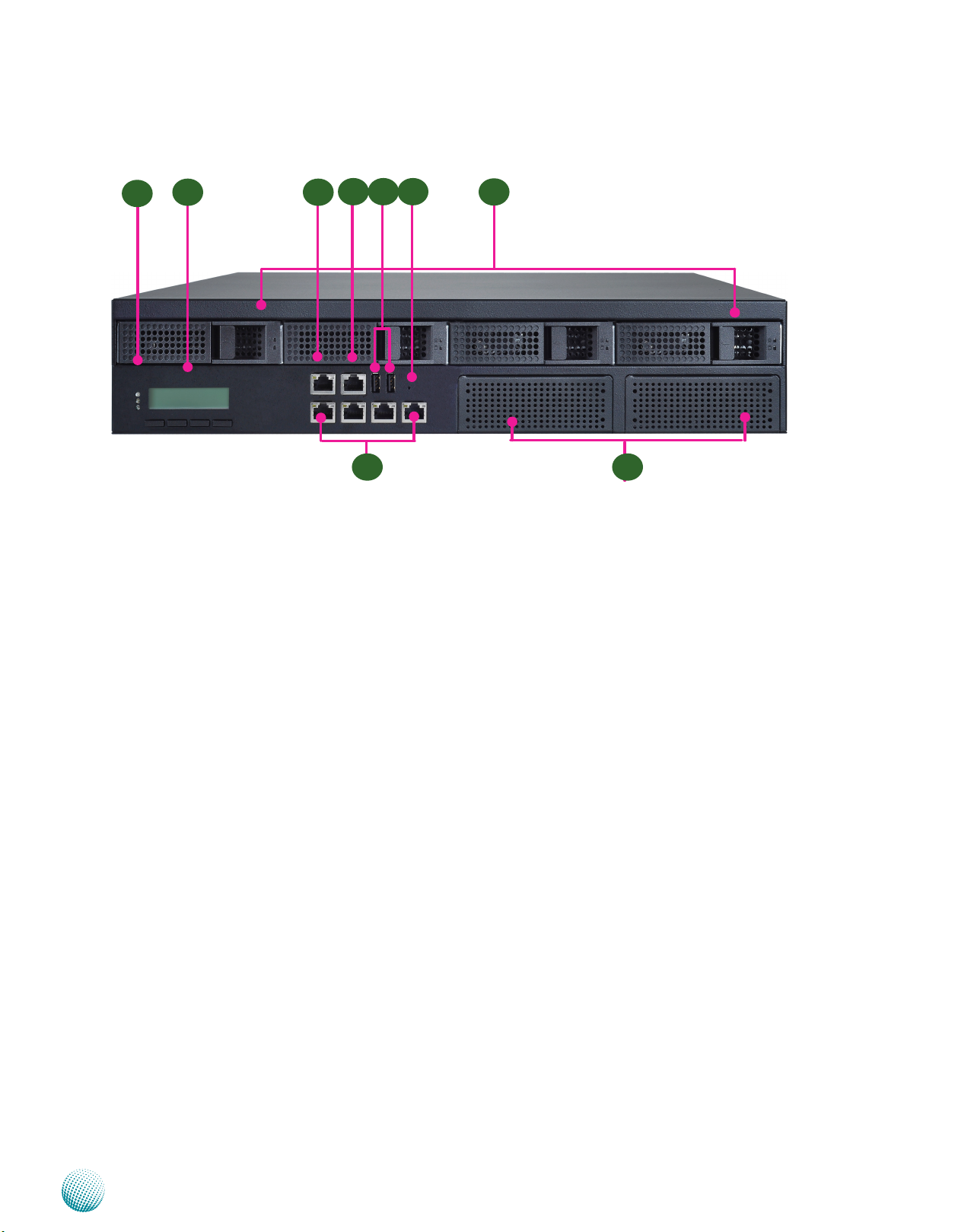
F1
F1 Power/Status/HDD LED
F2 F3
F4
LAN1 LAN2 LAN3 LAN4
F6F5
Introduction
F9
F7F8
Power: If the LED is on it indicates that the system is powered on. If it is off, it indicates that the system is powered off.
Status: This LED is programmable. You could program it to display the operating status with the behavior like:
If the LED is green, it indicates that the system’s operational state is normal. If it is red, it indicates that the system is
malfunctioning.
HDD: If the LED blinks, it indicates data access activities; otherwise, it remains off.
F2 System Panel: LCD System Panel
The LCD System Panel can be programmed to display operating status and configuration information. For more details
or sample programming code, please refer to the Drivers and user’s manual CD.
F3 Management Port (provided by Realtek RTL8110SC)
This FastEthernet port can be connected for configuration or troubleshooting purpose. A conformity with IPMI (Intelligent
Platform Management Interface) can be implemented through OPMA on this interface. It is also capable of Preboot
eXecution Environment (PXE) to boot computers using a network interface. (This feature can be enabled or disable in
the BIOS; the default is disabled).
F4 Console Port
By using suitable rollover cable or RJ-45 to DB-9 Female (Cisco console cable), you can connect to a computer terminal
for diagnostic or configuration purpose. Terminal Configuration Parameters: 115200 baud, 8 data bits, no parity, 1 stop
bit , no flow control.
F5 Two USB 2.0 Ports
It connects to any USB devices, for example, a flash drive.
F6 Reset Switch
The reset switch can be used to reboot the system without turning off the power.
F7 Swappable Ethernet Modules (with LAN bypass options)
F8 Ethernet Ports (LAN1-LAN2: bypass pair; LAN3-LAN4: bypass pair)
LINK/ACT (Yellow)
On/Flashing: The port is linking and active in data transmission.•
Off: The port is not linking.•
SPEED (Green/Amber)
Network Application Platforms
3
Page 9

Chapter 1
Amber: The connection speed is 1000Mbps.•
Green: The connection speed is 100Mbps•
Off: .The connection speed is 10Mbps.•
4 on-board Ethernet ports with 2 pairs of LAN bypass. The 4 port lan module is provided by Intel i350. With Intel
i350, it equips with Intel Virtualization for Connectivity (VT-c) as part of the Intel Virtualization Technology to improve
networking and I/O throughput on a virtualized system (The Intel VT is a hardware-assisted virtualization. This
processor of the system supports Intel Virtualization. You need to enable or disable this feature in the BIOS menu).
Moreover, 2 pairs (LAN1-LAN2, LAN3-LAN4) can be configured as LAN Bypass when failure events occur. This feature
can be enabled dynamically with a watch dog timer. Refer to your User’s Manual CD for a sample implementation of
this feature.
Note:
The availability of LAN Bypass varies depending on the model of Ethernet LAN module. For more 1.
information, visit the Lanner product website at www.lannerinc.com/x86_Network_Appliances/Network_
Modules
The number of LAN ports varies depending on the module. 2. For more information on customization of
Lanner network modules, visit the Lanner product website at www.lannerinc.com/x86_Network_Appliances/
Network_Modules:
The management port is optional depending on the model.3.
Introduction
F8 Hot-swappable Hard Disk Modules
Two of them support SATA 3.0 (SATA 1 and SATA2) and the other two support SATA 2.0 (SATA3 and SATA4). Refer to
Chapter 3 Motherboard Information for SATA connectors.
Network Application Platforms
4
Page 10
Chapter 1
Introduction
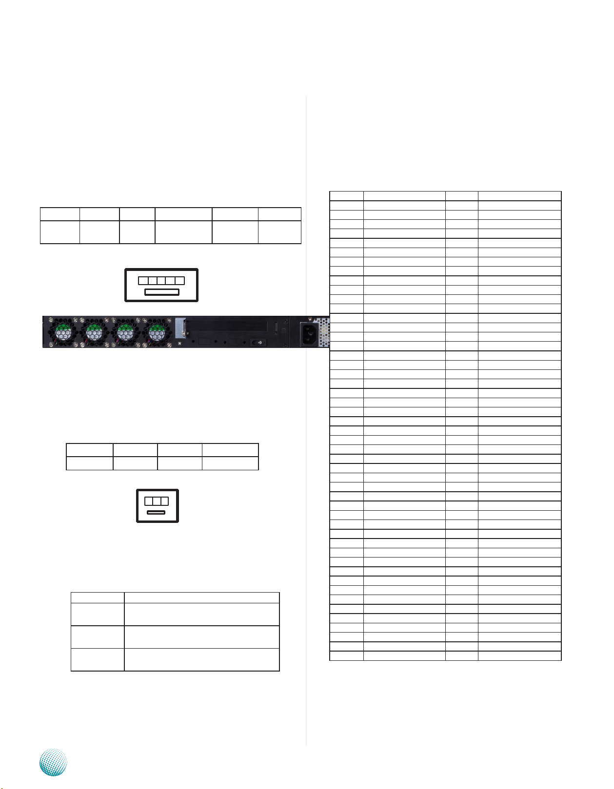
Rear Panel Features
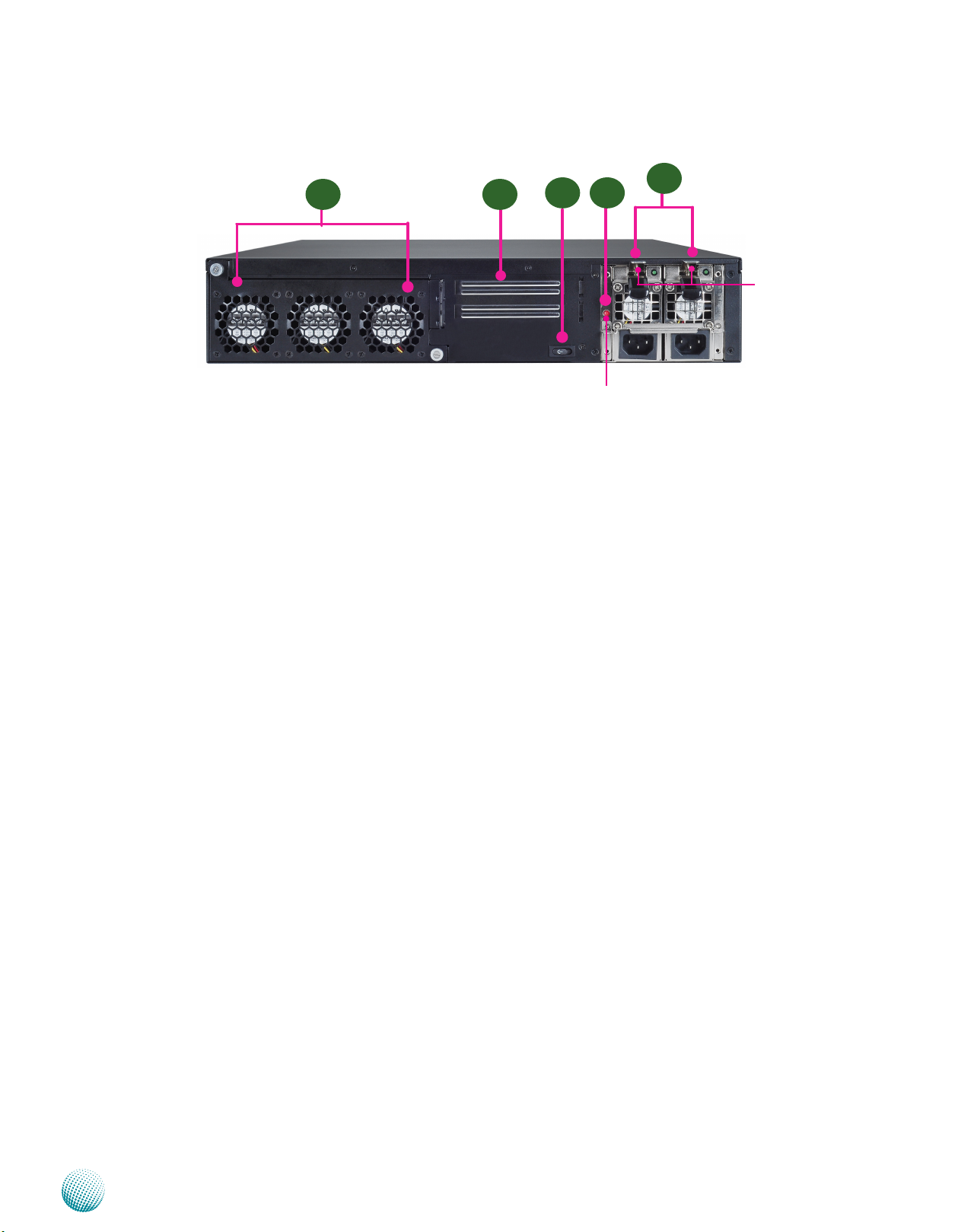
R3
R1 R2
R1 Hot-swappable Modular Fans
These fans have smart fan feature which can be turned on automatically when the temperature exceed the set
threshold.
R2 PCIe Expansion Slot
R3 Power-on Switch
It is a switch to turn on or off the power.
R4 Power Supply Alarm Switch
R4
PSU Alarm Switch
R5
PSU latch
screw
When the alarm sounds (it indicates a power supply failure), switch off this button to turn off the alarm. Replace the failed
power supply as soon as possible.
R5 Redundant Power Supply
The 350W redundant power supply is hot-swappable and can be withdrawn and replaced when the alarm sounds. The
LED of the failed power supply will be turned off. To replace the failed power supply unit, unscrew the screw and press
the latch to release the unit and pull it out.
Network Application Platforms
5
Page 11
Chapter 2
Chapter 2:
Hardware Setup
Hardware Setup
Preparing the Hardware Installation
To access some components and perform certain service
procedures, you must perform the following procedures
first.
WARNING: To reduce the risk of personal injury,
electric shock, or damage to the equipment,
remove the power cord to remove power from the
server. The front panel Power On/Standby button
does not completely shut off system power.
Portions of the power supply and some internal
circuitry remain active until AC power is removed.
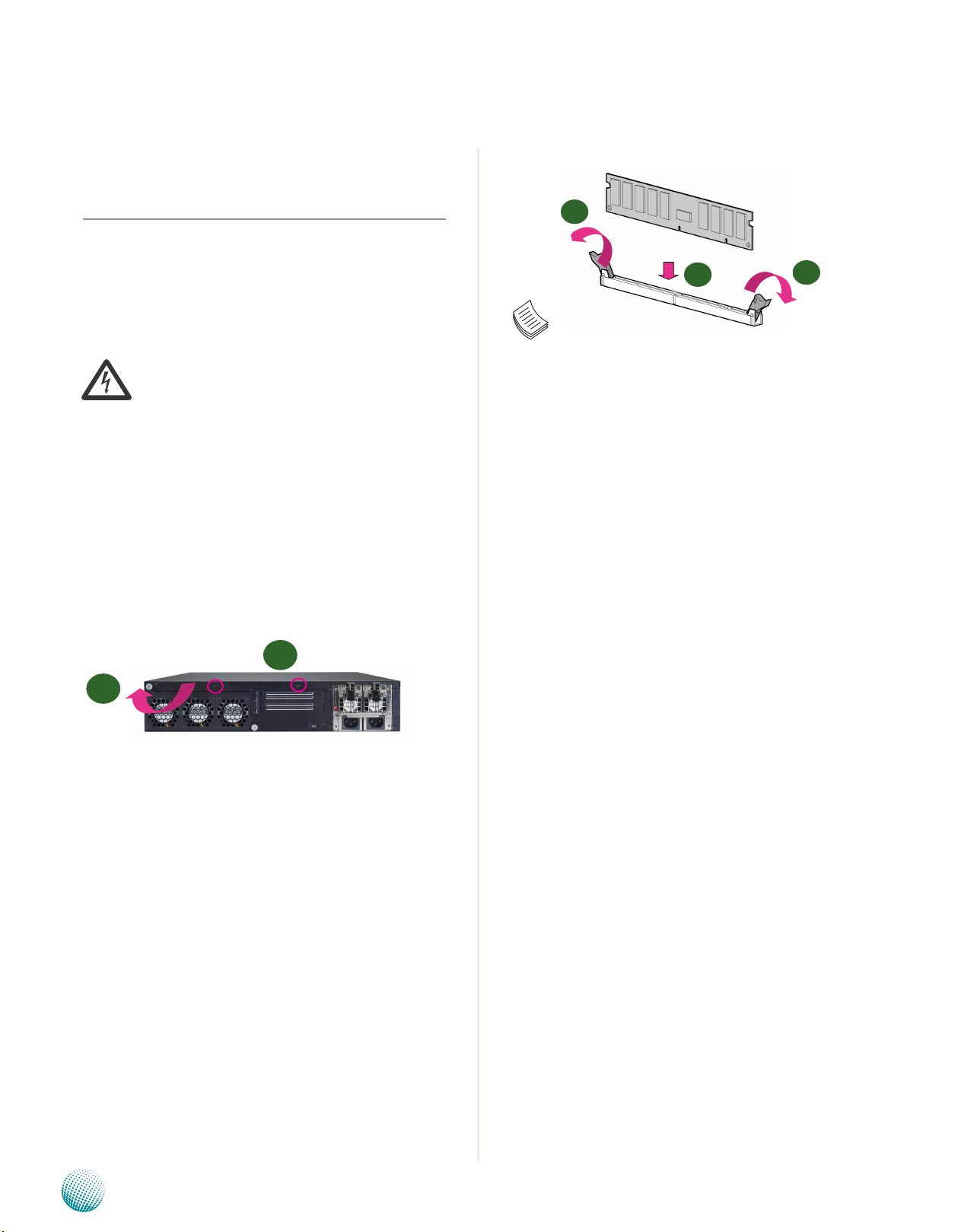
Unpower the FX-3210 and remove the power cord.1.
Unscrew two screws on the back of top cover .2.
Slide the cover backwards and open the cover 3.
upwards.
1
2
Note:
All DIMMs installed must be the same speed 1.
(DDR3 1066, 1333 or 1600, unbuffered ECC or
non-ECC). Do not install DIMMs supporting
different speeds. The DDR3 1600 is supported on
the Ivy Bridge platform only.
The system can support up to 32 GB in maximum.2.
Since the system is capable of Dual Channel 3.
Architecture, some installation guidelines have to
be met to enable Dual Channel mode as directed.
To insert two DIMMs on the system, insert DIMMS
on slot J2 (blue) and J4 (blue). And use slot J3
(black) and J5 (black) if more slots are required.
(Use slot J3 and then slot J5 in sequence for the
additional DIMMS.)
1
1
2
Installing the System Memory
The motherboard supports DDR3 memory that features
data transfer rates of 1066, 1333 or 1600 MHz to meet the
higher bandwidth requirements of the latest operating
system and Internet applications. To install the memory:
Open the DIMM slot latches.1.
Install the DIMM.2.
Network Application Platforms
6
Page 12
Chapter 2
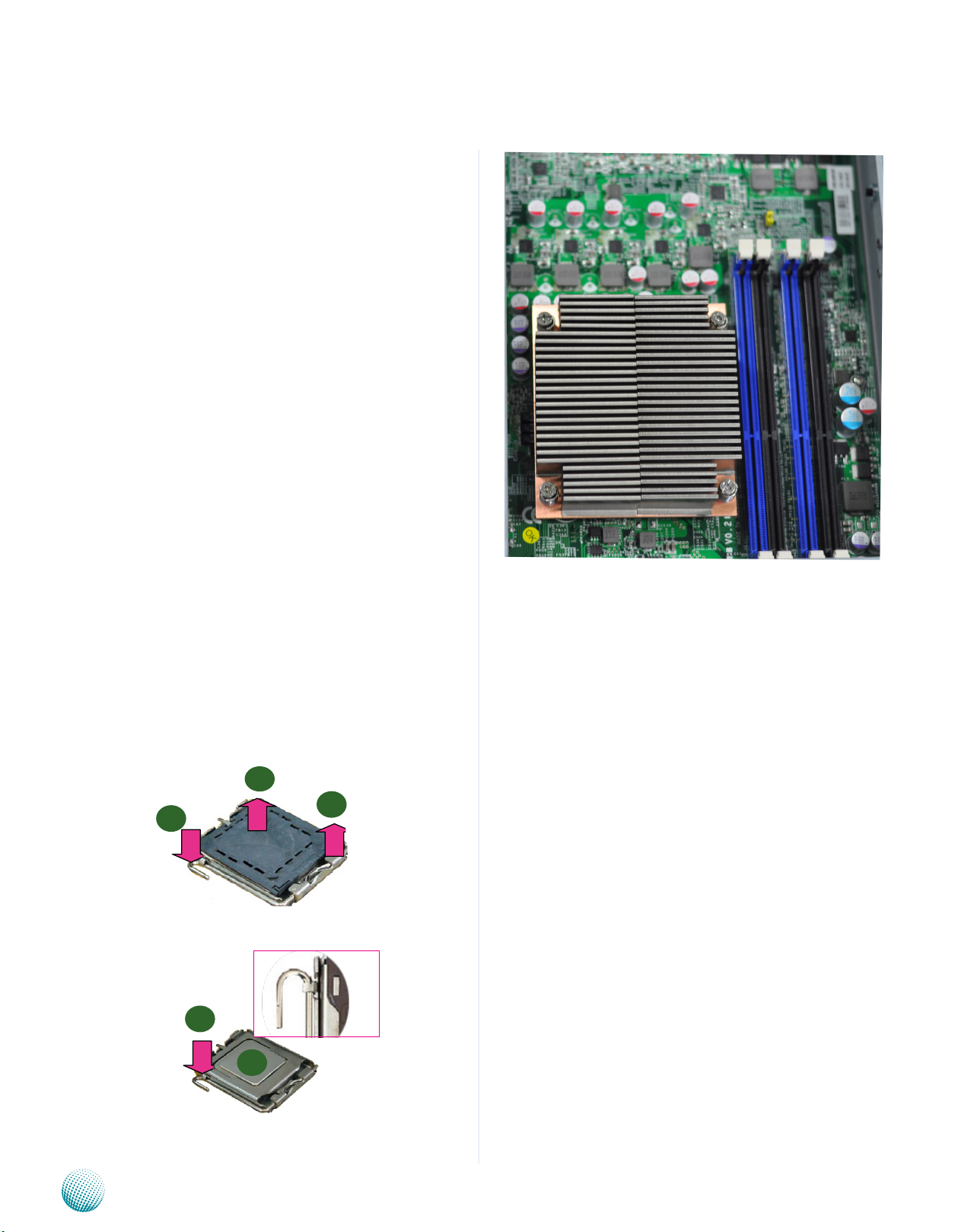
CPU and the Heat Sink Installation
The FX-3210 sever system is powered by the MB-8865
sever board, which comes with one ZIF type LGA1155 CPU
socket.
Follow the procedures bellow for installing a CPU
Remove the CPU socket cap.1.
Press the load lever and release it from the retention 2.
tab.
Lift the load lever and then the plate.3.
Align the cut-out of the CPU and the notch on the 4.
socket. The CPU should fit perfectly into the socket.
Note that the CPU fits in the socket in only one
direction.
Close the plate and push the load lever to lock it back 5.
to the retention tab.
Hardware Setup
Peel off the sticker on the CPU to expose the thermal 6.
compound.
Put the heat sink on top of the installed CPU, and match 7.
the screws with the screw holes on the board. Fasten
two screws which are opposite to each other at a time
and then the other two. It is easier this way because of
the force of the spring.
Place the heat sink cover on top of the installed heat 8.
sink and screw the three screws to fasten it on the
case.
1
3
2
Note:
The CPU heat sink can only be installed in only 1.
one orientation as shown in the picture.
To protect the CPU socket pins, retain the CPU 2.
cap when the CPU is not installed.
5
4
Network Application Platforms
7
Page 13
Chapter 2
Hardware Setup
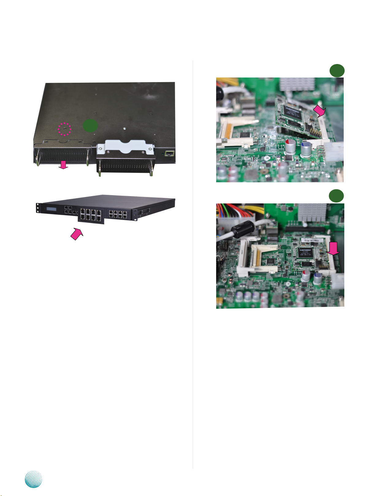
Front Ethernet Module Installation
1
IPMI Card Installation
1
2
To install the front Ethernet module, take off the front 1.
bezel first by unfastening the threaded screws on the
bottom of the case.
Insert the Ethernet module into the front expansion 2.
slot. You should hear a click when the module connects
to the system’s mainboard.
Fasten the screw back on the bottom of the case to 3.
secure the module on the system.
To install the IPMI card, align the notch of DIMM with 1.
the slot key on the socket.
Press the card to insert the card into the socket until it 2.
snaps with the retaining clips.
Network Application Platforms
8
Page 14
Chapter 2
Hardware Setup
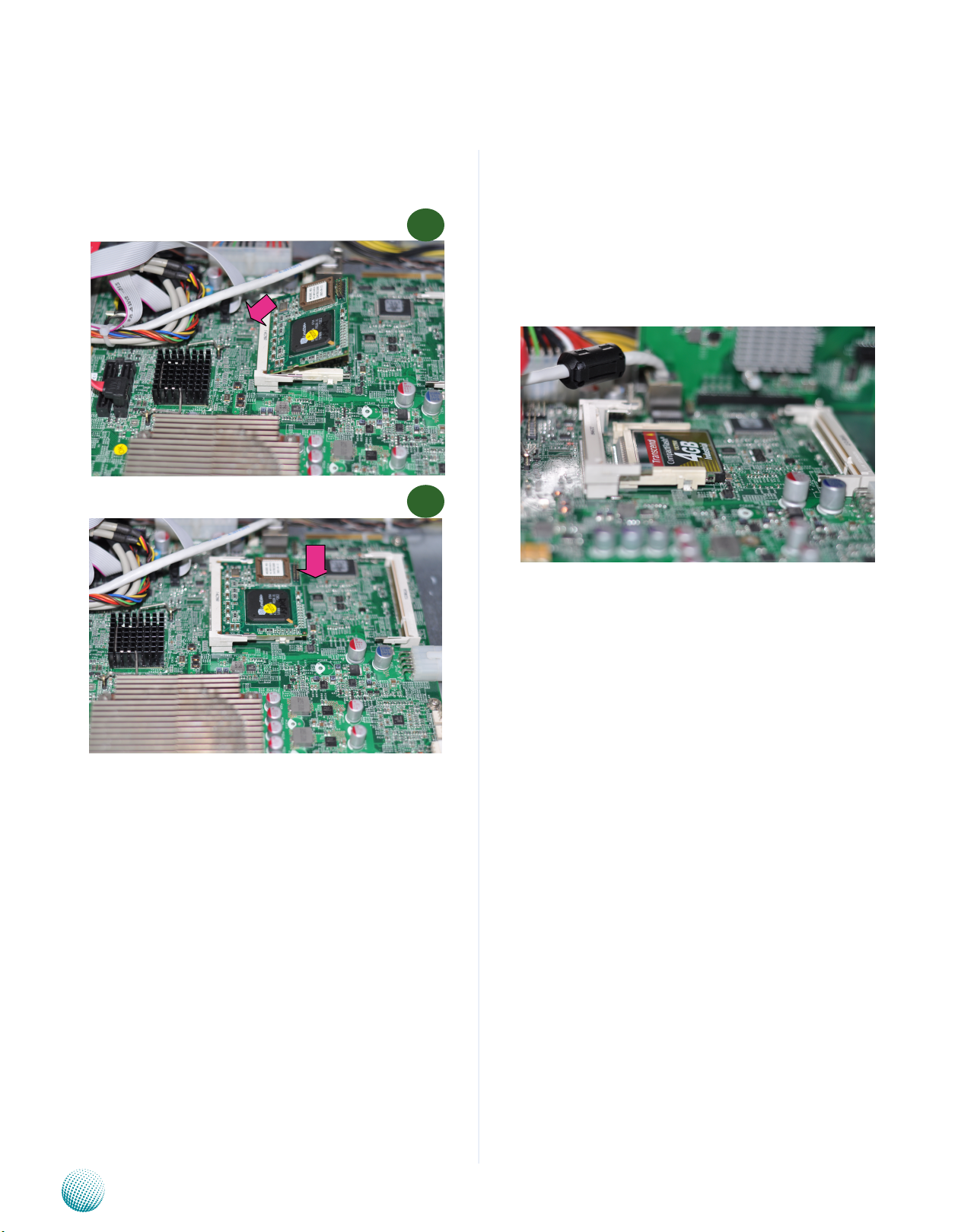
Mini PCI Expansion Card Installation
Installing a CompactFlash Card
FX-3210 provides one CompactFlash slot. Follow the
1
2
procedures bellow for installing a CompactFlash card.
Align CompactFlash card and the card slot with the 1.
arrow pointing toward the connector.
Push the card to insert into the connector.2.
To install the PCI expansion module, align the PCI 1.
notch on the card with the slot key on the socket.
Insert the PCI card into the slot. Press the card firmly 2.
until the card is installed securely.
Network Application Platforms
9
Page 15
Chapter 3
ˣ˖˜ˀ˘ʳˋʳ˿
˙ʳ˹ʳ
ˡ˜˖ʳ˷˿˸
˖˴˶ʳ˙˿˴˻
ˇʳ
˦˔˧˔
˖ʳˣ
˟˖ˠ˂
˞˸ʳˣ˴˷
˞˕˂
ˠ˸
˚ˣ˜ˢ
˙˴ʳˠ˼
˅ʳ˨˦˕
˅ʳ˻˸˴˷˸
W83627DHG
˧˻˸˴˿ʳˠ˼
˖˺˴ʳˣ˼
ˣ˖˛
ˠ˼˼ˀˣ˖˜
ˣ˖˜ˀ˘ʳˋʳ˿
˙ʳ˹ʳ
ˡ˜˖ʳ˷˿˸
LCM Module
< A
V >
ˡ˜˖ʳ˿ʳ˄
ˡ˜˖ʳ˿ʳ˅ ˡ˜˖ʳ˿ʳˆ
˥˼˸
W83627DHG
MUX
Pericom
Chapter 3: Motherboard Information
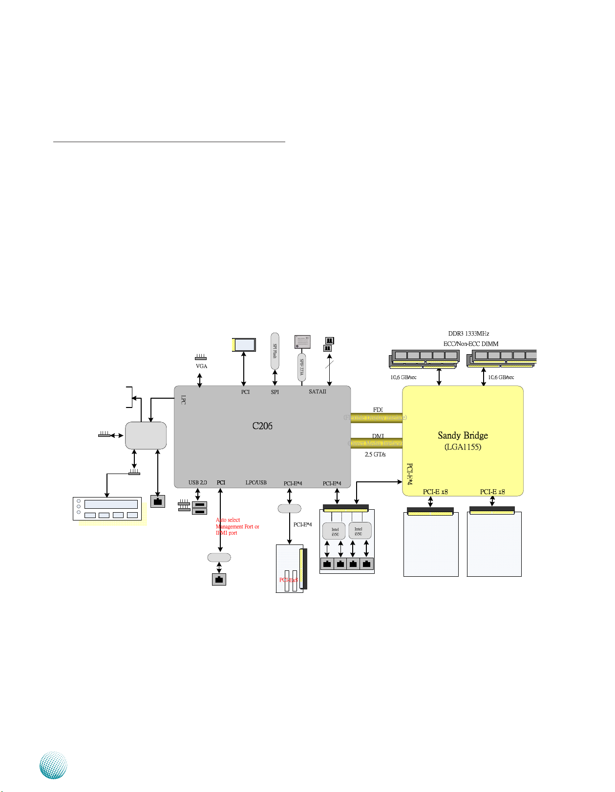
Block Diagram
The block diagram depicts the relationships among the
interfaces or modules on the motherboard. Please refer
to the following figure for your motherboard’s layout
design.
Motherboard Information
Network Application Platforms
10
Page 16
Chapter 3
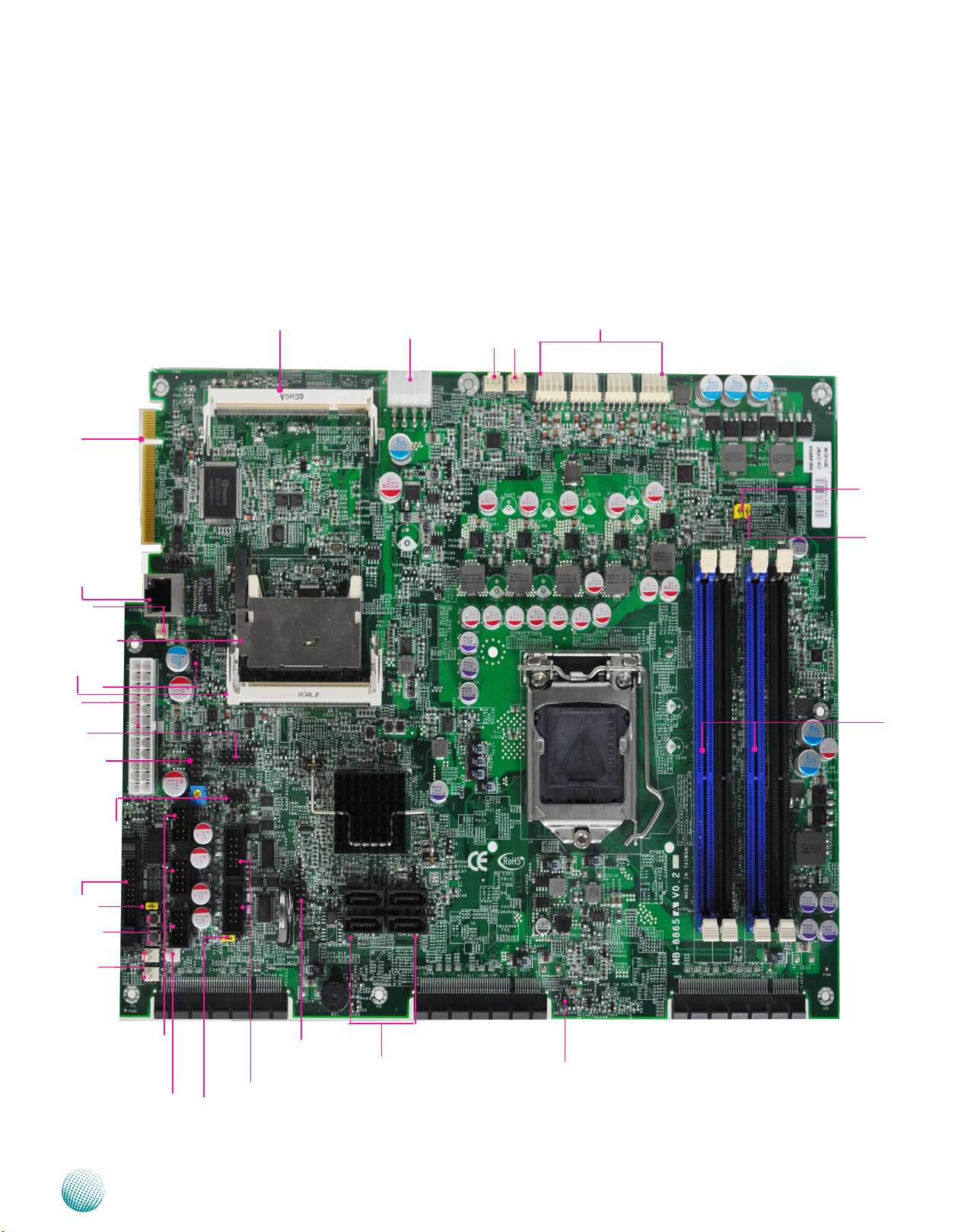
Motherboard Layout
The motherboard layout shows the connectors and
jumpers on the board. Refer to the following picture
as a reference of the pin assignments and the internal
connectors.
Motherboard Information
PCI-E Golden Finger
connector (PCIEC4)
MGT1
J15
Co mpa ct Fl ash
Card
connector (CF1)
PCIB1 (Mini-PCI
Connector)
J28
ATX1
VGAA1
J29
OPMA Slot (OPMA1)
ATX2
CONN2
FAN1 FAN2 FAN3 FAN4
FAN5
CP U P CI E
S e l e ct i o n
(J31)
CP U PC IE
order (J32)
J2/J3/J4/J5
J10
J14
J13
SW2
SW1
TTL2/
TTL1
PCI-E expansion
USBA3
connector (PCIEC3)
USBA2
USBA1
CONN1
J8
Network Application Platforms
COMB1
COMB2
SPI-ROM1
SATA3
SATA4
SATA1
SATA2
PCI-E expansion
connector (PCIEC1)
J17
PCI-E expansion
connector (PCIEC2)
11
Page 17
Chapter 3
Motherboard Information
Jumper Settings
Fan Connectors(FAN1/FAN2/FAN3/FAN4): The 5-pin
connector is for connecting the CPU fans. It comes
with the smart fan feature by which the fans could
be monitored and turned on when the temperature
exceed the set threshold. Connect CPU fans to
FAN1and FAN3, and connect auxiliary fans to FAN2
and FAN4.
Pin No. 1 2 3 4 5
Function PWM NC FANIN VFAN GROUND
1 2 3 4 5
FAN4 FAN3 FAN2 FAN1
AUX Fan CPU Fan AUX Fan CPU Fan
Fan Connectors(FAN5): The 3-pin connector is for
connecting the chassis fan.
Function Ground +12V AUXFANIN1
PIN NO. 1 2 3
3 2 1
PCIe Connectors(PCIEC4/PCIEC3/PCIEC1/PCIEC2): It is
for connecting the expansion cards which might be
an Ethernet card or a RAID card. These PCIE sockets
oers a variation of PCIe lanes as listed below.
Jumper Function
PCIEC1/2 PCI Express x8 SLOT having PCIe x8
mode
PCIEC3 PCI Express x8 SLOT having 2 PCIe x4
or 4 PCIe x1 mode
PCIEC4 PCI Express x8 golden nger having 1
PCIE x4 mode
PCIEx8 Connector running at PCIEx8 mode
(PCIEC1,PCIEC2): to be connected to the front Ethernet
module. The jumper J31 can be used to select the
PCIe mode of these two connectors and jumper J32
can be used to select the order of the signal. Note
that with Ivy Bridge CPU, the PCIE also upgrades to
PCIe 3.0 standard (currently PCIe 2.0).
PIN NO. FUNCTION PIN NO. FUNCTION
B1 +12V A1 PRSNT1#
B2 +12V A2 +12V
B3 +12V A3 +12V
B4 GND A4 GND
B5 SMCLK A5 JTAG2
B6 SMDAT A6 JTAG3
B7 GND A7 JTAG4
B8 +3.3V A8 JTAG5
B9 JTAG1 A9 +3.3V
B10 3.3VAUX A10 +3.3V
B11 WAKE# A11 PERST#
B12 BYPASS0 Mode A12 GND
B13 GND A13 REFCLKA+
B14 CPUPETP7/CPUPETP15 A14 REFCLKAB15 CPUPETN7/CPUPETN15 A15 GND
B16 GND A16 CPUPERP7/CPUPERP15
B17 LANM0_LATCH_H A17 CPUPERN7/CPUPERN15
B18 GND A18 GND
B19 CPUPETP6/CPUPETP14 A19 BYPASS1 Mode
B20 CPUPETN6/CPUPETN14 A20 GND
B21 GND A21 CPUPERP6/CPUPERP14
B22 GND A22 CPUPERN6/CPUPERN14
B23 CPUPETP5/CPUPETP13 A23 GND
B24 CPUPETN5/CPUPETN13 A24 GND
B25 GND A25 CPUPERP5/CPUPERP13
B26 GND A26 CPUPERN5/CPUPERN13
B27 CPUPETP4/CPUPETP12 A27 GND
B28 CPUPETN4/CPUPETN12 A28 GND
B29 GND A29 CPUPERP4/CPUPERP12
B30 REFCLK1A+ A30 CPUPERN4/CPUPERN12
B31 REFCLK1A- A31 GND
B32 GND A32 LANM1_LATCH_H
B33 CPUPETP3/CPUPETP11 A33 LANM1_LATCH_L
B34 CPUPETH3/CPUPETH11 A34 GND
B35 GND A35 CPUPERP3/CPUPERP11
B36 GND A36 CPUPERN3/CPUPERN11
B37 CPUPETP2/CPUPETP10 A37 GND
B38 CPUPETN2/CPUPETN10 A38 GND
B39 GND A39 CPUPERP2/CPUPERP10
B40 GND A40 CPUPERN2/CPUPERN10
B41 CPUPETP1/CPUPETP9 A41 GND
B42 CPUPETN1/CPUPETN9 A42 GND
B43 GND A43 CPUPERP1/CPUPERP9
B44 GND A44 CPUPERN1/CPUPERN9
B45 CPUPETP0/CPUPETP8 A45 GND
B46 CPUPETN0/CPUPETN8 A46 GND
B47 GND A47 CPUPERP0/CPUPERP8
B48 LANM0_LATCH_L A48 CPUPERN0/CPUPERN8
B49 GND A49 GND
Network Application Platforms
12
Page 18

Chapter 3
Motherboard Information
PCIEx8 connector running at 2 PCIEx4 or 4 PCIEx1 mode
(PCIEC3): to be connected to the front Ethernet
module. It complies with PCIe 2.0 standard.
PIN NO. FUNCTION PIN NO. FUNCTION
B1 +12V A1 PRSNT1#
B2 +12V A2 +12V
B3 +12V A3 +12V
B4 GND A4 GND
B5 SMCLK A5 JTAG2
B6 SMDAT A6 JTAG3
B7 GND A7 JTAG4
B8 +3.3V A8 JTAG5
B9 JTAG1 A9 +3.3V
B10 3.3VAUX A10 +3.3V
B11 WAKE# A11 PERST#
B12 BYPASS0 Mode A12 GND
B13 GND A13 REFCLKA+
B14 EX_CPUPETP3 A14 REFCLKAB15 EX_CPUPETN3 A15 GND
B16 GND A16 EX_CPUPERP3
B17 LANM0_LATCH_H A17 EX_CPUPERN3
B18 GND A18 GND
B19 EX_CPUPETP2 A19 BYPASS1 Mode
B20 EX_CPUPETN2 A20 GND
B21 GND A21 EX_CPUPERP2
B22 GND A22 EX_CPUPERN2
B23 EX_CPUPETP1 A23 GND
B24 EX_CPUPETN1 A24 GND
B25 GND A25 EX_CPUPERP1
B26 GND A26 EX_CPUPERN1
B27 EX_CPUPETP0 A27 GND
B28 EX_CPUPETN0 A28 GND
B29 GND A29 EX_CPUPERP0
B30 REFCLK1A+ A30 EX_CPUPERN0
B31 REFCLK1A- A31 GND
B32 GND A32 LANM1_LATCH_H
B33 SBPETP3 A33 LANM1_LATCH_L
B34 SBPETH3 A34 GND
B35 GND A35 SBPERP3
B36 GND A36 SBPERN3
B37 SBPETP2 A37 GND
B38 SBPETN2 A38 GND
B39 GND A39 SBPERP2
B40 GND A40 SBPERN2
B41 SBPETP1 A41 GND
B42 SBPETN1 A42 GND
B43 GND A43 SBPERP1
B44 GND A44 SBPERN1
B45 SBPETP0 A45 GND
B46 SBPETN0 A46 GND
B47 GND A47 SBPERP0
B48 LANM0_LATCH_L A48 SBPERN0
B49 GND A49 GND
PCIEx8 Golden Finger running at 1 PCIEx4 mode
(PCIEC4):to be connected to the PCIe expansion slot
on the back panel via a riser card. Note that if this
port is connected, some applications of IPMI that
requires VGA function such as remote desktop will be
disabled.
PIN NO. FUNCTION PIN NO. FUNCTION
B1 +12V A1 PRSNT1#
B2 +12V A2 +12V
B3 +12V A3 +12V
B4 GND A4 GND
B5 SMCLK A5 JTAG2
B6 SMDAT A6 JTAG3
B7 GND A7 JTAG4
B8 +3.3V A8 JTAG5
B9 JTAG1 A9 +3.3V
B10 3.3VAUX A10 +3.3V
B11 WAKE# A11 PERST#
B12 RESV A12 GND
B13 GND A13 REFCLKA+
B14 RESV A14 REFCLKAB15 RESV A15 GND
B16 GND A16 RESV
B17 RESV A17 RESV
B18 GND A18 GND
B19 RESV A19 RESV
B20 RESV A20 GND
B21 GND A21 RESV
B22 GND A22 RESV
B23 RESV A23 GND
B24 RESV A24 GND
B25 GND A25 RESV
B26 GND A26 RESV
B27 RESV A27 GND
B28 RESV A28 GND
B29 GND A29 RESV
B30 RESV A30 RESV
B31 RESV A31 GND
B32 GND A32 RESV
B33 SBPETP4 A33 RESV
B34 SBPETH4 A34 GND
B35 GND A35 SBPERP4
B36 GND A36 SBPERN4
B37 SBPETP5 A37 GND
B38 BPETN5 A38 GND
B39 GND A39 SBPERP5
B40 GND A40 SBPERN5
B41 SBPETP6 A41 GND
B42 SBPETN6 A42 GND
B43 GND A43 SBPERP6
B44 GND A44 SBPERN6
B45 SBPETP7 A45 GND
B46 SBPETN7 A46 GND
B47 GND A47 SBPERP7
B48 RESV A48 SBPERN7
B49 GND A49 GND
Network Application Platforms
13
Page 19

Chapter 3
MINIPCI1
Motherboard Information
Mini-PCI Connector (PCIB1): The Mini-PCI slot enables a
Mini-PCI expansion module to be connected to the
board.
2 4 6 8 124
1 3 5 7 123
PIN NO. FUNCTION PIN NO. FUNCTION
1 TIP 2 RING
3 8PMJ-3 4 8PMJ-1
5 8PMJ-6 6 8PMJ-2
7 8PMJ-7 8 8PMJ-4
9 8PMJ-8 10 8PMJ-5
11 LED1_GRNP 12 LED2_YELP
13 LED1_GRNN 14 LED2_YELP
15 CHSGND 16 RESERVED
17 INT-B 18 +5V
19 +3.3V 20 INT-A
21 RESERVED 22 RESERVED
23 GROUND 24 3.3VAUX
25 CLK 26 RST
27 GROUND 28 +3.3V
29 REO 30 GNT
31 +3.3V 32 GROUND
33 AD31 34 PME
35 AD29 36 RESERVED
37 GROUND 38 AD30
39 AD27 40 +3.3V
41 AD25 42 AD28
43 RESERVED 44 AD26
45 C_BE-3 46 AD24
47 AD23 48 IDSEL
49 GROUND 50 GROUND
51 AD21 52 AD22
53 AD19 54 AD20
55 GROUND 56 PAR
57 AD17 58 AD18
59 C_BE-2 60 AD16
61 IRDY 62 GROUND
63 +3.3V 64 FRAME
65 CLKRUN 66 TRDY
67 SERR 68 STOP
69 GROUND 70 +3.3V
71 PERR 72 DEVSEL
73 C_BE-1 74 GROUND
75 AD14 76 AD15
77 GROUND 78 AD13
79 AD12 80 AD11
81 AD10 82 GROUND
83 GROUND 84 AD9
85 AD8 86 C_BE-0
87 AD7 88 +3.3V
89 +3.3V 90 AD6
91 AD5 92 AD4
93 RESERVED 94 AD2
95 AD3 96 AD0
97 +5V 98 RESERVED-WIP
99 AD1 100 RESERVED-WIP
111 MOD_AUDIO_
MON
113 AUDIO_GND 114 GROUND
115 SYS_AUDIO_OUT 116 SYS_AUDIO_IN
117 SYS_AUDIO_OUT
GND118
119 AUDIO_GND 120 AUDIO_GND
121 RESERVED 122 MPCIACT
123 +5V 124 +3.3 STBY
112 RESERVED
118 SYS_AUDIO_IN GND
ATX Power Connector(ATX1, ATX2): These 24-pin and
8-pin connectors are for connecting ATX power
supply plugs. Find the proper orientation when
inserting the plugs, for the supply plugs are
designed to t these connectors in only one
orientation.
Pin No. Function
1 GND
2 GND
3 GND
4 GND
5 +12V
6 +12V
7 +12V
8 +12V
23
21
19
17
15
13
11
1 2 3 4
(lower)
5 6 7 8
(upper)
Pin No. Function Pin NO. Function
24
1 +3.3V 2 +3.3V
22
3 +3.3V 4 -12V
20
5 GROUND 6 GOUND
18
7 +5V 8 PSON-
16
9 GROUND 10 GROUND
14
11 +5V 12 GROUND
12
9
7
5
3
1
13 GROUND 14 GROUND
10
15 POWER GOOD 16 NC
8
17 STAND-BY 5V 18 +5V
6
19 +12V 20 +5V
4
21 +12V 22 +5V
2
23 +3.3V 24 GROUND
AT Mode Power Button Connector (J15): It is for connecting
the power switch in AT mode
1
2
Pin No. Function
1 PS_ON#
2 GND
AT Mode Jumper(J17): It is for adjusting the jumper setting
for the system power to be in ATX mode if AT Mode
Power Button Connector (J15) is used.
Pin No. Function
1
2
-- Normal (Default ATX Mode)
1-2 AT mode
Network Application Platforms
14
Page 20

Chapter 3
25 1
50 26
CF1
Motherboard Information
Clear CMOS jumper (J8): It is for clearing the CMOS
memory and system setup parameters by erasing
the data stored in the CMOS RAM such as the
system passwords.
1 2 3
Pin No. Function
1-2 (Default) Normal
2-3 Clear CMOS
CompactFlash Connector (CF1): It is for connecting a
Compact Flash card to be served as your system’s
storage. The connector is a CF Type II slot which could
fit both CF Type I or CF Type II cards.
DIMM Socket (J2/J3/J4/J5): The 240-pin DDR3 DIMM is for
connecting the DDR3 1066/1333/1600 (unbuffered
ECC or non-ECC) memory. The system can support
up to 32 GB in maximum. A DDR3 module has the
same physical dimensions as a DDR2 DIMM but the
notch on the pins is positioned differently. Channel
information lists below:
J2 Channel A DIMM0 (blue)
J3 Channel A DIMM1 (black)
J4 Channel B DIMM0 (blue)
J5 Channel B DIMM1 (black)
Note: Since the system is capable of Dual
Channel Architecture, some installation
guidelines have to be met to enable Dual
Channel mode as directed. To insert two DIMMs
on the system, insert DIMMS on slot J2 (blue)
and J4 (blue). And use slot J3 (black) and J5
(black) if more slots are required. (Use slot J3
and then slot J5 in sequence for the additional
DIMMS.)
SATA 1, 2 and 3, 4 Connectors (SATA1/SATA2/SATA3/
Pin No. Function Pin No. Function
1 Ground 2 Data 3
3 Data 4 4 Data 5
5 Data 6 6 Data 7
7 CE1# 8 N.C.
9 Ground 10 N.C.
11 N.C. 12 N.C.
13 +3.3V 14 N.C.
15 N.C. 16 N.C.
17 N.C. 18 Addr 2
19 Addr 1 20 Addr 0
21 Data 0 22 Data 1
23 Data 2 24 WP
25 CD2- 26 CD127 Data 11 28 Data 12
29 Data 13 30 Data 14
31 Data 15 32 CE2#
33 N.C. 34 IOR#
35 IOW# 36 WE#
37 READY# 38 +3.3V
39 CSEL. 40 N.C.
41 RESET 42 WAIT#
43 INPACK# 44 REG#
45 DASP# 46 DIAG#
47 Data 8 48 Data 9
49 Data 10 50 Ground
SATA4): It is for connecting a 2.5’’ SATA harddisk to
be served as your system’s storage. The system can
accommodate up to 2 disks (2.5" or 1disk for 3.5")
in maximum. SATA1 and SATA2 comply fully with
SATA Revision 3.0 standard with data transfer rates
of up to 6.0 Gb/s. SATA3 and SATA4 support SATAT
revision 2.0. The controller contains two modes of
operation—a legacy mode using I/O space, and an
AHCI mode using memory space. Software that
uses legacy mode will not have AHCI capabilities.
The AHCI ( Advanced Host Controller Interface) is a
programming interface which defines transactions
between the SATA controller and software and
enables advanced performance and usability with
SATA. Platforms supporting AHCI may take advantage
of performance features such as no master/slave
designation for SATA devices—each device is treated
as a master—and hardware assisted native command
queuing. AHCI also provides usability enhancements
such as Hot-Plug. Note you will need to configure
your SATA as AHCI or RAID in the BIOS.
Note:
To configure your Hard disk using the 1.
integrated RAID feature, the Intel®Rapid
Storage Technology Utility has to be installed
on your Operating System.
You will need to select the RAID mode in the 2.
BIOS for your SATA drives first. There is also a
Network Application Platforms
15
Page 21

Chapter 3
Motherboard Information
Intel® RSTe OpROM utility for creating RAID
volume; to enter the RSTe OpROM, press Ctrl-I
during POST.
For operating systems other than Microsoft3. ®
Windows Vista and Windows® 7, it is
required to pre-install the Intel Rapid Storage
Technology driver during the F6 installation of
Windows setup (“press F6 if you need to install
a third party SCSI or RAID driver....”).
Visit the Intel support page at http://www.intel.
com/p/en_US/support/highlights/chpsts/imsm
for more information and download links.
The Intel controller hubs are also supported 4.
by Linux. Beginning with Linux kernel
version 2.6.27, the mdadm utility 3.0
supports RAID 0, RAID 1, RAID 5, and RAID
10.
To use the RAID features in dmraid and mdadm,
you will need to set up the RAID volume using
the Intel® Matrix Storage Manager option ROM
(click CTRL + I when prompted during boot to
enter the option ROM user interface).
Power-switch Connector (SW1, CONN1): A tact as well as
the connector for switch button used for turning on or off
the power once the power supply is applied to the board.
4
2
Pin No. Pin name
1 GND
2 GND
3 PS_ON#
4 PS_ON#
3
1
1
2
Pin No. Pin name
1 GND
2 PS_ON#
USB Connector(USBA1&USBA2) : It is for connecting
the USB module cable. It complies with USB2.0 and
support up to 480 Mbps connection speed.
LED Signals on RJ45 port of the PCI-e Expansion Card : A
LED connector showing the LEDs of the RJ45 ports
10
8
6
4
2
Pin No. Function Pin No. Function
1 LED_SPEED_100 2 NC
3 LED_SPEED_1G 4 NC
5 LINK/ACT 6 NC
7 P3V3_DUAL 8 P3V3_DUAL
9 Ground 10 Ground
9
7
5
3
1
LPC I/O bus (It can also be called Port 80) (LPC1): It is a
proprietary connector for connecting a checkpoint
device to output checkpoints throughout booting
and Power-On Self Test (POST) to indicate the task
the system is currently executing.
9 7 5 3 1
10 8 6 4 2
Pin No. Function Pin No. Function
1 CLK_33M_P80 2 LPC_LAD1
3 RST_80DGPT_N 4 LPC_LAD0
5 LPC_FRAME_N 6 +3.3V
7 LPC_LAD3 8 Ground
9 LPC_LAD2 10 Ground
Front LCD Module Connector(J14): The 24-pin connector
is for connecting the front system panel.
24
23
PIN NO. Function Pin No. Function
1 +5V 2 Ground
3 LSLIN# 4 VEE
5 LAFD# 6 LINIT#
7 FL_PD1 8 FL_PD0
9 FL_PD3 10 FL_PD2
11 FL_PD5 12 FL_PD4
13 FL_PD7 14 FL_PD6
15 LCD- 16 +5V
17 KPA1 18 KPA2
19 KPA3 20 KPA4
2
21 LCM_RST 22 CTR-GRN
1
23 CTR-YEW 24 HDLED_N
1
3
5
7
9
Pin No. Function Pin No. Function
1 USB_VCC0 2 USB_VCC1
3 USBD0- 4 USBD1-
5 USBD0+ 6 USBD1+
7 USB Port Ground 8 USB Port Ground
9 USB Port Ground 10 USB Port Ground
2
4
6
8
10
Network Application Platforms
Keyboard and Mouse Interface Cable Connectors (J10):
It is for connecting the PS/2 keyboard and mouse
interface cable.
2 4 6 8
1 3 5 7
Pin No. Function Pin No. Function
1 P5V 2 MSCLK
3 MSDATA 4 KEY
5 KBDATA 6 KEY
7 GND 8 KBCLK
16
Page 22

Chapter 3
Motherboard Information
Hardware or Software Reset Jumper(J13): The jumper can
be adjusted to be in either hardware or software reset
mode when the reset switch is pressed. The hardware
reset will reboot the system without turning off the
power. The software reset can be programmed to
reset a software to its default setting.
3 2 1
Pin No. Function
1-2 Hardware Reset
2-3 Software Reset
Power Failure Detection Jumper (TTL1/TTL2): This two-
pin jumper can be used for power failure detection.
Connect the redundant power 1 and redundant
power 2 to TTL1 and TTL2 respectively in order to
monitor the availability of them.
Pin No. Function (TTL1)
1
2
1 GND
2 RDPW_TTL1_GP37
Pin No. Function (TTL2)
1 GND
2 RDPW_TTL2_GP36
Pin No. Function (10/100) PIN NO.(10/100/1000)
1 TX+ MD0+
2 TX- MD03 RX+ MD1+
4 T45 MD2+
5 T45 MD26 RX- MD17 T78 MD3+
8 T78 MD3-
9 LINK_1000_N
10 LINK_100_N
11 LINK/ACT_N
12 PULLHIGH
Power-switch Connector (SW2): A tact for rebooting the
system.
4
2
Pin No. Pin name
1 GND
2 GND
3 RESET#
4 RESET#
3
1
Serial Interface Connectors(COMB1/COMB2): It is for
connecting the RS-232 serial port interface cable.
10
8
6
4
2
.
Pin NO. Function PIN NO.
1 Data Carrier Detect (DCDB#) 2 Data Set Ready (DSRB#)
3 Receive Data (RXDB) 4 Request To Send (RTSB#)
5 Transmit Data (TXDB) 6 Clear To Send (CTSB#)
7 Data Terminal Ready (DTRB #)r 8 Ring Indicator (RIB #)
9 Ground 10 Key
9
7
5
3
OPMA Slot (OPMA1): This is an optional OPMA (Open
Platform Management Architecture ) slot on the
board. Through this card, the IPMI (Intelligent
Platform Management Interface) implementation can
be realized. Note that if the PCIe expansion golden
finger-PCIEC4 is connected, some applications of IPMI
that requires VGA function such as remote desktop
will be disabled.
Management Port (MGT1, provided by Realtek RTL8110SC):
The management port provides connects to the
front management port. It can be an IPMI compliant
management with the OPMA card; otherwise, it is just
a normal management port.
Network Application Platforms
17
Page 23

Chapter 3
Motherboard Information
SPI-ROM Update Connector (SPI-ROM1): Using the
appropriate cable to connect this 10-pin ISP in header
connector, the user can update the SPI Flash soldered
on board.
1
3
5
7
9
2
Pin No. Function Pin NO. Function
1 SPI_HD1_N 2 PCH_SPI_CS1_N
4
3 SPI_CS0 4 V_3P3_SPI
6
5 SPI_ICH_MISO_R 6 SPI_HOLD0_L
8
7 NC 8 SPI_ICH_CLK_R
10
9 Ground 10 SPI_ICH_MOSI_R
VGA Interface (VGAA1): It is for connecting the VGA
interface cable (2X6 pin to female DB15 connector)
2 4 6 8 10
1 3 5 7 9
Pin No. Function PIN NO. Function
1 R 2 Ground
3 G 4 Ground
5 B 6 Ground
7 H-SYNC 8 NC
9 V-SYNC 10 Ground
11 Detect-display Data 12 Deteck-display CLOCK
USB and COM Interface signal for LCM card (J29)
10
8
6
4
2
Pin No. Function PIN NO. Function
9
7
5
3
1
1 P5V_DUAL 2 P5V
3 USB- 4 NC
5 USB+ 6 HDD_LED7 GND 8 GND
9 NXP_TXD 10 NXP_RXD
Pin Header for Power Management Port (J28)
1
2
3
4
5
Pin No. Function
1 PSUMAN_SMBCLK
2 NC
3 GND
4 PSUMAN_SMBDATA
5 P5V
Case Open Signal (CONN2)
Pin No. Function
1 GND
3 2 1
Network Application Platforms
2 CASE OPEN
3 GND
PCIe mode selection for PCIe expansion integrated directly
into the CPU (PCIEC1 and CPIEC2):J31
1
2
3
Pin No. Function
1-2 CPU PCIE divide to
X8,X4,X4
2-3 CPU PCIE divide to
2 PCIEx8 (default)
PCIe signal order selection (J32): PCIe signal order selection
for PCIe expansion integrated directly into the CPU:
PCIEC1, PCIEC2, and PCIEC3
PCIEC1/PCIEC2
1
2
3
PIN NO. FUNCTION PIN NO. FUNCTION
B1 +12V A1 PRSNT1#
B2 +12V A2 +12V
B3 +12V A3 +12V
B4 GND A4 GND
B5 SMCLK A5 JTAG2
B6 SMDAT A6 JTAG3
B7 GND A7 JTAG4
B8 +3.3V A8 JTAG5
B9 JTAG1 A9 +3.3V
B10 3.3VAUX A10 +3.3V
B11 WAKE# A11 PERST#
B12 BYPASS0 Mode A12 GND
B13 GND A13 REFCLKA+
B14 CPUPETP0/CPUPETP8 A14 REFCLKAB15 CPUPETN0/CPUPETN8 A15 GND
B16 GND A16 CPUPERP0/CPUPERP8
B17 LANM0_LATCH_H A17 CPUPERN0/CPUPERN8
B18 GND A18 GND
B19 CPUPETP1/CPUPETP9 A19 BYPASS1 Mode
B20 CPUPETN1/CPUPETN9 A20 GND
B21 GND A21 CPUPERP1/CPUPERP9
B22 GND A22 CPUPERN1/CPUPERN9
B23 CPUPETP2/CPUPETP10 A23 GND
B24 CPUPETN2/CPUPETN10 A24 GND
B25 GND A25 CPUPERP2/CPUPERP10
B26 GND A26 CPUPERN2/CPUPERN10
B27 CPUPETP3/CPUPETP11 A27 GND
B28 CPUPETN3/CPUPETN11 A28 GND
B29 GND A29 CPUPERP3/CPUPERP11
B30 REFCLK1A+ A30 CPUPERN3/CPUPERN11
B31 REFCLK1A- A31 GND
B32 GND A32 LANM1_LATCH_H
B33 CPUPETP4/CPUPETP12 A33 LANM1_LATCH_L
B34 CPUPETH4/CPUPETH12 A34 GND
B35 GND A35 CPUPERP4/CPUPERP12
B36 GND A36 CPUPERN4/CPUPERN12
B37 CPUPETP5/CPUPETP13 A37 GND
B38 CPUPETN5/CPUPETN13 A38 GND
B39 GND A39 CPUPERP5/CPUPERP13
B40 GND A40 CPUPERN5/CPUPERN13
B41 CPUPETP6/CPUPETP14 A41 GND
B42 CPUPETN6/CPUPETN14 A42 GND
B43 GND A43 CPUPERP6/CPUPERP14
B44 GND A44 CPUPERN6/CPUPERN14
B45 CPUPETP7/CPUPETP15 A45 GND
B46 CPUPETN7/CPUPETN15 A46 GND
B47 GND A47 CPUPERP7/CPUPERP15
B48 LANM0_LATCH_L A48 CPUPERN7/CPUPERN15
B49 GND A49 GND
Pin No. Function
1-2 The PCIE signal in reverse
order (default)
2-3 The PCIE signal in positive
order
18
Page 24

Chapter 3
PCIEC3
PIN NO. FUNCTION PIN NO. FUNCTION
B1 +12V A1 PRSNT1#
B2 +12V A2 +12V
B3 +12V A3 +12V
B4 GND A4 GND
B5 SMCLK A5 JTAG2
B6 SMDAT A6 JTAG3
B7 GND A7 JTAG4
B8 +3.3V A8 JTAG5
B9 JTAG1 A9 +3.3V
B10 3.3VAUX A10 +3.3V
B11 WAKE# A11 PERST#
B12 BYPASS0 Mode A12 GND
B13 GND A13 REFCLKA+
B14 EX_CPUPETP0 A14 REFCLKAB15 EX_CPUPETN0 A15 GND
B16 GND A16 EX_CPUPERP0
B17 LANM0_LATCH_H A17 EX_CPUPERN0
B18 GND A18 GND
B19 EX_CPUPETP1 A19 BYPASS1 Mode
B20 EX_CPUPETN1 A20 GND
B21 GND A21 EX_CPUPERP1
B22 GND A22 EX_CPUPERN1
B23 EX_CPUPETP2 A23 GND
B24 EX_CPUPETN2 A24 GND
B25 GND A25 EX_CPUPERP2
B26 GND A26 EX_CPUPERN2
B27 EX_CPUPETP3 A27 GND
B28 EX_CPUPETN3 A28 GND
B29 GND A29 EX_CPUPERP3
B30 REFCLK1A+ A30 EX_CPUPERN3
B31 REFCLK1A- A31 GND
B32 GND A32 LANM1_LATCH_H
B33 SBPETP3 A33 LANM1_LATCH_L
B34 SBPETH3 A34 GND
B35 GND A35 SBPERP3
B36 GND A36 SBPERN3
B37 SBPETP2 A37 GND
B38 SBPETN2 A38 GND
B39 GND A39 SBPERP2
B40 GND A40 SBPERN2
B41 SBPETP1 A41 GND
B42 SBPETN1 A42 GND
B43 GND A43 SBPERP1
B44 GND A44 SBPERN1
B45 SBPETP0 A45 GND
B46 SBPETN0 A46 GND
B47 GND A47 SBPERP0
B48 LANM0_LATCH_L A48 SBPERN0
B49 GND A49 GND
Motherboard Information
Network Application Platforms
19
Page 25

Chapter 4
Chapter 4: BIOS Settings
Updating the BIOS
The Basic Input/Output System (BIOS) can be updated
using the designated Flash Utility. To obtain the utility,
please contact us either through the sales rep or technical
support.
Note:
For the update version of the BIOS image, please
visit Lanner’s support page at
http://assist.lannerinc.com. Then select support
center from the Main Menu and look under the
folder for the desired product category. The
resources for each product including the BIOS
image will be contained within a folder named by
the product model.
Bios Settings
Network Application Platforms
20
Page 26

Chapter 4
Accessing the BIOS menu
When you are installing a motherboard or when the
system prompts “Run Setup” during start-up, you will use
the BIOS Setup program to configure the system, . This
section explains how to configure your system using this
program.
Even if you are not prompted to enter the BIOS Setup
program when you are installing a motherboard, you can
still change the configuration of your computer later on
with this program. For example, you may want to enable
the security password feature or change the power
management settings. This requires you to reconfigure
your system by using the BIOS Setup program so that the
computer can recognize these changes and record them
in the CMOS RAM .
When you start up the computer, the system provides you
with the opportunity to run this program. Press <Delete>
during the Power-On-Self-Test (POST) to enter the Setup
utility (There are a few cases that other keys may be
used, such as <F1>, <F2>, and so forth.); otherwise, POST
continues with its test routines.
If you wish to enter Setup after POST, restart the system
by pressing <Ctrl+Alt+Delete>, or by pressing the reset
button on the system chassis. You can also restart by
turning the system off and then back on. Do this last
option only if the first two failed.
The Setup program is designed to make it as easy to use as
possible. Being a menu-driven program, it lets you scroll
through the various sub-menus and make your selections
from the available options using the navigation keys.
Bios Settings
Keys Description
-><- Left/Right The Left and Right <Arrow> keys
->
->
Up/Down The Up and Down <Arrow> keys
+- Plus/Minuss The Plus and Minus <Arrow> keys
Tab The <Tab> key allows you to select
allow you to select an setup screen.
For example: Main screen, Advanced
screen, Boot screen, and so on.
allow you to select an setup item or
sub-screen.
allow you to change the field value
of a particular setup item. For
example: Date and Time.
setup fields.
Note: This manual describes the standard look of
the setup screen. There may be some instances in which
the motherboard features can vary from one to another
due to customization. This means that some of the options
described in this manual mays not match that of your
motherboard’s AMIBIOS.
Navigating the BIOS menu
The BIOS setup utility uses a key-based navigation system
called hot keys. Most of the BIOS setup utility hot keys can
be used at any time during the setup navigation process.
These keys include <F1>, <F10>, <Enter>, <ESC>, <Arrow>
keys, and so on.
Network Application Platforms
Note: The <F8> key on your keyboard is the Fail-Safe key.
It is not displayed on the key legend by default. To set the
Fail-Safe settings of the BIOS, press the <F8> key on your
keyboard. The Fail-Safe settings allow the motherboard
to boot up with the least amount of options set. This can
lessen the probability of conflicting settings.
21
Page 27

Chapter 4
The Main Menu
The main BIOS setup menu is the first screen that you can
navigate. Each main BIOS setup menu option is described
in this chapter.
The Main BIOS setup menu screen has two main frames. The
left frame displays all the options that can be configured.
“Grayed-out” options are configured parameters and
cannot be modified. On the other hand, Options in blue
can be modified.
The right frame displays the key legend. Above the key
legend is an area reserved for a text message. When an
option is selected in the left frame, it is highlighted in
white. Often a text message will accompany it.
Bios Settings
System Language
Use this item to choose the BIOS language.
System Time/System Date
Use this option to change the system time and date.
Highlight System Time or System Date using the <Arrow>
keys. Enter new values through the keyboard. Press the
<Tab> key or the <Arrow> keys to move between fields.
The date must be entered in MM/DD/YY format. The time
is entered in HH:MM:SS format.
Network Application Platforms
22
Page 28

Chapter 4
Advanced Settings
Select the Advanced tab from the setup screen to enter
the Advanced BIOS Setup screen. You can select any of
the items in the left frame of the screen, such as SuperIO
Configuration, to go to the sub menu for that item. You
can display an Advanced BIOS
Setup option by highlighting it using the <Arrow> keys.
All Advanced BIOS Setup options are described in this
section. The Advanced BIOS Setup screen is shown at
the right. The sub menus are described on the following
pages.
Bios Settings
PXE Function
The Preboot eXecution Environment (PXE) allows you to
boot computers using a network interface independently
of data storage devices (like hard disks) or installed
operating systems. Enable or disable this function with
this option here.
CPU Configuration Settings
You can use this screen to view the capabilities and of your
CPU. You can also use this menu to enable/disable certain
functions of your CPU. Use the up and down <Arrow> keys
to select an item. Use the <Plus> and <Minus> keys to
change the value of the selected option. A description of
the selected item appears on the right side of the screen.
The settings are described below.
Item Selection
Intel HyperThreading
Active Processor Core
The Intel Hyper-Threading Technology
allows a hyper-threading processor to
appear as two logical processors to the
operating system, allowing the operating system to schedule two threads or
processes simultaneously.
Select to enable or disable this feature.
Select the number of processor cores to
be active in each processor package.
Network Application Platforms
23
Page 29

Chapter 4
Item Selection
Limit CPUID
Maximum
Execute Disable Bit
Intel Virtualization
Hardware
Prefetcher
Adjacent
Cache Line P
Allows legacy operating systems to boot
even without support CPUs with extended CPUID functions.
Select to enable or disable this function
Select to enable or disable the No-Execution Page Protection Technology.
The Intel VT is a hardware-assisted virtualization. This processor supports Intel Virtualization. Enable or disable this feature.
The processor has a hardware prefetcher
that automatically prefetches data and instructions from the memory into the Level
2 cache that are likely to be required in
the near future. This reduces the latency
associated with memory reads.
When enabled, the processor’s hardware
prefetcher will be enabled and allowed to
automatically prefetch data and code for
the processor.
When disabled, the processor’s hardware
prefetcher will be disabled.
Select to enable or disable prefetching of
adjacent line
Bios Settings
SATA Controllers Configuration Settings
While entering Setup, the BIOS automatically detects
the presence of SATA devices. The SATA Port items show
“Empty” if no SATA device is installed to the corresponding
SATA port.
SATA Controllers
Item Selection
Enable or
Disable SATA
Controller(s)
Network Application Platforms
Set this value to enable or disable SATA
controllers
24
Page 30

Chapter 4
SATA Mode Selection
The system supports advanced SATA features such as
software RAID.
Item Selection
IDE Mode Set to IDE mode when your want to use the
Serial-ATA hard disk drives as Parallel ATA physical
storage devices.
AHCI Mode Set to AHCI mode when you want the SATA
hard disk drives to use the AHCI (Advanced
Host Controller Interface). The AHCI allows the
onboard storage driver to enable advanced SATA
features that increases storage performance or
workloads where multiple simultaneous read/
write requests are outstanding, most often
occurring in server-type applications (native
command queuing). It also facilitates hot
swapping.
RAID Set to the RAID mode when you want to create
a RAID configuration from the SATA Hard disk
drives. Thie chipset supports software RAID by
using the Intel® Matrix Storage Manager
software. For more information, visit
http://www.intel.com/design/chipsets/
matrixstorage_sb.htm#benefit
Bios Settings
Serial ATA Port 0/1/2/3
Use this menu to configure specific SATA Port for all ports
on the system.
Option Description
Software
Preserve
Port 0 Enable or disable the specific port
Hot Plug The AHCI of SATA provides hot plug capability
External
SATA
SATA Device
type
Spin Up
Device
Network Application Platforms
In order to avoid losing important software
settings without legacy driver knowledge, the
software settings preservation ensures that
the value of important software settings is
maintained across a COMRESET
to allow drives to be added or removed with the
PC running.
Called external SATA or eSATA, you can now
utilize shielded cable lengths up to 2 meters
outside the PC to transform SATA to be an
external storage. enable or disable this feature.
Select the SATA type from either Hard Disk Drive
or Solid State Drive
Spin-up is a simple mechanism by which the
storage subsystem controller can sequence
hard disk drive initialization and spin-up.set to
control whether each specific drive will spin up.
25
Page 31

Chapter 4
USB Configuration Setting
You can use this screen to select options for the USB
Configuration. Use the up and down <Arrow> keys to
select an item. Use the <Plus> and <Minus> keys to
change the value of the selected option. The settings are
described on the following pages.
Legacy USB Support
This option enable or disable the support for USB devices
on legacy operating systems (OS), e.g., Windows ME/98/
NT, and MS-DOS. Normally if this option is not enabled,
any attached USB mouse or USB keyboard will not become
available until a USB compatible operating system is fully
booted with all USB drivers loaded. When this option is
enabled, any attached USB mouse or USB keyboard can
be used on the system even when there is no USB drivers
loaded on it.
Bios Settings
Option Description
Auto Allow the system to detect the presence of USB
devices at startup. If detected, the USB controller
legacy mode is enabled If it is not detected, the
USB control er legacy mode is disabled.
Enabled Enable the support for USB devices on legacy
operating system
Disabled Disable this function.
EHCI Hand-Off
It allows you to enable support for operating systems which do
not have the Enhanced Host Controller Interface hand-off (EHCI
hand-off ) feature for USB devices.
Option Description
Enabled Enable this feature
Disabled Disable this feature
Network Application Platforms
26
Page 32

Chapter 4
USB Hardware Delays a
The menu sets delay time for USB operations.
Item Description
USB transfer
time-out
Device reset
time-out
Device
power-up
delay
set transfers to an endpoint to complete
within a specic time.
•Ifsettozero,transferswillnottimeout
because the host controller will not cancel
the transfer. In this case, the transfer waits
indenitely until it is manually canceled or
the transfer completes normally.
•Ifsettoanonzerovalue(time-outinterval), the host controller starts a timer when
it receives the transfer request. When the
timer exceeds the set time-out interval, the
request is canceled.
This option sets the reset timing for the
USB Mass Storage to be initialized.
When set to 10 Sec, the BIOS will wait for
up to 30 seconds for the USB ash drive to
initialize.
This option sets the power-up timing for
the USB Mass Storage to be initialized.
Bios Settings
Network Application Platforms
27
Page 33

Chapter 4
SuperIO Configuration
In this screen, you will be able to modify the IRQ address
of the serial and parallel ports which are provided by the
Winbond W83627DHG chip.
Serial Port 0/1 Configuration
This option specifies the base I/O port address and
Interrupt Request address of serial port 0 and 1.
Bios Settings
item Selection
Enabled/
Disabled
Change
Settings
Set this value to prevent the serial port from
accessing any system resources. When this
option is set to Disabled, the serial port physically
becomes unavailable.
Selects the serial port base address and IRQ for
the interrupt address.
Parallel Port Configuration
This option specifies the I/O address used by the parallel
port.
Item Selection
Parallel Port Enable or disable this parallel port
Device
Settings
Device Mode Selects the modes from the following possibilities:
Selects the serial port base address
STD Printer, Standard Parallel Port (SPP), Enhanced
Parallel Port (EPP) and Extended Capabilities Port
(ECP). Currently, new products have support of a
mixture of these protocols. Consult your device’s
specification for exact protocols supported by
your product.
SPP: denotes normal or standard mode.
EPP: used specifically for non-printer devices that
would attach to the parallel port, particularly
storage devices that needed the highest possible
transfer rate.
Network Application Platforms
ECP: used specifically to provide improved speed
and functionality for printers
28
Page 34

Chapter 4
PC Health Status
This menu shows the hardware monitor configuration
settings. Select an item then press <Enter> to display the
configuration options.
SYSIN/CPUIN/AUXIN Temperature
The onboard hardware monitor automatically detects and
displays the CPU and motherboard temperatures.
FAN1/FAN2/FAN3/FAN4 Speed
The onboard hardware monitor automatically detects
and displays the CPU , chassis and system fan speeds in
rotations per minute (RPM). If the fan is not connected to
the motherboard, it displays N/A.
CPU Voltage, 3.3V voltage, 5V voltage, 12V voltage
Bios Settings
The onboard hardware monitor automatically detects the
voltage output through the onboard voltage regulators.
Smart Fan Mode Configuration
It allows you to configure the smart fan feature. You
can manually turn on the CPU fan or set the target CPU
temperature at which the CPU fan will start running if the
fan is not yet turned on. And the CPU fan can also be turned
off automatically if the temperature for the CPU is at or
below the specified value. Refer to Motherboard Layout on
Chapter 3 Block Diagram for CPU fan connectors.
Item Selection
Manual
Mode
Smart Fan
Control
Manually set the fan speed
set the target system temperature at which
the system fan will start running if the fan is
not yet turned on with this mode. And the
system fan can also be turned o automatically if the temperature for the system is at
or below the specied value.
FCTRL5/FCTRL6 FAN Mode
The FCTRL5 is for setting the parameters for FAN2 and
FAN4 for CPU fans.
The FCTRL6 is for setting the parameter for FAN1 and FAN3
for Auxiliary fans.
Network Application Platforms
29
Page 35

Chapter 4
Console Redirection
Use this menu to set the settings for BIOS remote access
feature.
Item Selection
Console Redirection Enable or disable BIOS
through remote access
Console Redirection Settings
COM0/COM1 Console Redirection Settings
Item Selection
Terminal Type Sets the connection termi-
Bits per second, Data bits,
Parity, Stop Bits, Flow
Control
Enter to view more options
nal type
Sets the terminal connec-
tion parameters such as
the baud rate, parity check
mechanism, etc.
Bios Settings
Network Application Platforms
30
Page 36

Chapter 4
Lan Bypass Control
In this screen, you can configure the Lan Bypass
functionality. The system have 3 LAN modules: Left
module and two expansion models: M1 and M2 on the
right (when facing the front panel).
LAN Bypass for M1/M2/Left Modu1
You can activate or deactivate the Lan Bypass ports. For
the description of the physical ports that are capable of
the LAN Bypass function, refer to the Front Panel Feature in
Chapter 1 Introduction.
M1 denotes Ethernet expansion module No.1 and M2
denotes Ethernet module No.2.
Left Modu1 denotes the module on the far left when
facing the front panel. Note that Left Modu1 also
supports Lanner Generation 3 Bypass. See appendix
D Programming Generation 2 and 3 LAN Bypass for
more information
Bios Settings
SYSOFF bypass for M1/M2/Left Modu1
You can enable or disable the automatic activation of
hardware Lan Bypass function in the event of a power
failure. Hardware Bypass can automatically activate to
allow network traffic to continue.
The Lan bypass can be turned on or off in two system
states, i.e., power on and power off. The following are
the BIOS menu and illustration of the possibilities of LAN
bypass configuration in each state.
Bypass settings
System Status
Power on Enabled Disabled Enabled
Power o Bypass Bypass
Bypass settings
LAN Bypass for Port1 and
Port 2
Bypass Non-Bypass
LAN Bypass for Port1 and
Port 2
LAN Bypass 1&2 when
power o
LAN Bypass 1&2 when
power o
System Status
Power on Enabled Disabled Disabled
Non-Bypass Non-Bypass
Power o Non-Bypass Non-Bypass
Network Application Platforms
31
Page 37

Chapter 4
CPU PPM Configuration
In this section, you can configure the CPU Processor Power
Management.
EIST (Enhanced Intel SpeedStep Technology)
It allows you to enable or disable the EIST.
Option Description
Enable The operating system
controls the CPU speed
Disabled The CPU runs at its de-
fault speed.
Bios Settings
Enhanced Intel SpeedStep® technology (EIST) allows the
system to dynamically adjust processor voltage and core
frequency, which can result in decreased average power
consumption and decreased average heat production.
There are some system requirements must be met,
including CPU, chipset, motherboard, BIOS and operation
system. Please refer to Intel website for more information
Network Application Platforms
32
Page 38

Chapter 4
Chipset
The chipset menu will let you further configure your Intel
CPU and PCH capabilities:
PCH I/O Configuration
It shows the model name and version of the Intel Platform
Controller Hub on the system.
Bios Settings
USB Configuration
Item Selection
EHCI1/EHCI2 The EHCI specication describes a host
controller that correctly supports all
compliant USB 2.0 low-, full-, and highspeed devices. Select to either enable
or disable the controller.
SLP_S4 Assertion Width
Select the mininum assertion width of the SLP_S4# signal.
This field indicates the minimum assertion width of the
SLP__S4# signal to ensure that the DRAM modules have
been safely power-cycled. SLP_S4# is a signal for power
plane control. This signal shuts off power to all non-critical
systems when in the S4 (Suspend to Disk) or S5 (Soft Off )
state.
Network Application Platforms
33
Page 39

Chapter 4
Restore on AC Power Loss
This option lets you set the state of the system when it has
just recovered from a power outage.
Option Description
Power Off When setting to Power Off, the system goes into
“off state” after an AC power interruption.
Power On When setting to Power on, the system turns on
automatically after a power interruption
Last State When setting to Last State, the system goes
into whatever the state was before the power
interruption.
Bios Settings
Intel VT-d
Select to enable or disable the Intel Virtualization
Technology for Directed I/O” (VT-d). The Memory and
I/O virtualization are supported by the chipset as part
of Intel Virtualization Techonology for hardware-assisted
virtualization.
Memory Configuration
It shows the memory capacity of the system and the
installed memory on the system.
Network Application Platforms
34
Page 40

Chapter 4
Boot Setup
Select the Boot tab from the setup screen to enter the Boot
BIOS Setup screen. You can select any of the items in the
left frame of the screen, such as Boot Device Priority, to
go to the sub menu for that item. You can display an Boot
BIOS Setup option by highlighting it using the <Arrow>
keys. Select an item on the Boot Setup screen to access
the sub menus for the following described functions.
Boot Settings Configuration
In this screen, you will be able to configure the boot
procedures and the related elements.
Bios Settings
Items Options
Setup Prompt Timeout Specify the number of seconds
for the boot setup prompt to
wait for user’s intervention
during the POST.
Bootup Num-Lock State
Quiet Boot
GateA20 Active
This option lets you to
enable or disable the
function of the NumLock
key.
Enabling this item allows
the BIOS to suppress the
message displayed during
the POST.
This option sets the A20
address line controlling
method for handling above
1MB memory access. By
enabling the A20 gate, we
have access to all 32 lines on
the address bus, and hence,
can refrence 32 bit addresses,
or up to 0xFFFFFFFF - 4 GB
of memory. The controlling
mode includes:
Upon Request: when it is
enabled by user programs.
ALWAYS: never disables the
A20 line
Network Application Platforms
35
Page 41

Chapter 4
Items Options
Option ROM Messages
Interrupt 19 Trap Response
Boot Option Priorities
Hard Drive BBS Priorities
This option controls the
display of ROM messages
form the BIOS of add-
on devices such as the
graphics card or the SATA
controller during the start-
up sequence.
Force BIOS: When setting to
Force BIOS, third-party ROM
messages will be forced to
display during the start-up
sequence.
Keep Current: When setting to
Keep Current, third-party ROM
messages will only be displayed
if the device’s manufacturer has
set the add-on device to do so.
Set this value to configure
how option ROMs such as
network controllers trap
BIOS interrupt 19.
Use this screen to specify the
order in which the system
checks for the device to
boot from.
You will enter a submenu
that presents all the drives
connected to the system.
Here you can define the
boot order for the Hard
disks.
Bios Settings
Network Application Platforms
36
Page 42

Chapter 4
Security Settings
Select Security Setup from the Setup main BIOS setup
menu. All Security Setup options, such as password
protection and virus protection, are described in this
section. To access the sub menu for the following items,
select the item and press <Enter>:
Administrator Password
If you have set an administrator password, you should
enter the administrator password for accessing the system.
Otherwise, you will only be able to see or change selected
fields in the BIOS setup program.
Bios Settings
User Password
If you have set a user password, you must enter the user
password for accessing the system.
To set an Administrator/User password:
Select the option item and press Enter.1.
From the Create New Password box, key in a password, 2.
then press enter.
Confirm the password when prompted.3.
To change an administrator password:
Select the option item and press Enter.1.
From the Enter Current Password box, key in the 2.
current password, then press enter.
From the Create New Password box, key in a new 3.
password, then press Enter.
Confirm the password when prompted.4.
To clear the administrator password, follow the same steps
as in changing an administrator password, then press
Enter when prompted to create/confirm the password.
Network Application Platforms
37
Page 43

Chapter 4
Save & Exit
Select the Exit tab from the setup screen to enter the Exit
BIOS Setup screen. You can display an Exit BIOS Setup
option by highlighting it using the <Arrow> keys. The
following table lists the options in this menu.
Item Options
Saving Changes and Exit Select this option to save
changes and exit the BIOS
menu. It will automatically
resets if the changes made
require rebooting the
system to take effect.
Discard Changes and Exit Select this option to discard
changes and exit and BIOS
menu to continue the
booting process.
Save Changes and Reset When you have completed
the system configuration
changes, select this option
to leave setup and reboot
the computer so the new
system configuration
parameters can take effect.
Discard Changes and Reset This option allows you
to discard the selections
you made and restore the
previously saved values.
After selecting this option,
a confirmation appears.
Select Yes to discard any
changes and load the
previously saved values.
Save Changes Save your changes
Discard Changes Discard changes
Restore Defaults Restore to factory defaults
Save as User Defaults Save all of your changes as
an user default setting.
Restore User Defaults Loads your saved user
default setting.
Boot Override This section of the Boot
Menu allows booting from a
specific device immediately.
Therefore you should see
an entry for all bootable
devices.
Launch EFI Shell from
filesystem device
This option allows you to
attempt to launch the EFI
Shell application (shellx64.
e) from one of the avail-
able lesystem devices.
Bios Settings
Network Application Platforms
38
Page 44

Appendix A
Driver Installation
Appendix A: Driver Installation
Chipset Driver Installation
This section provides the instructions on how to install
Intel®Chipset Software Installation Utility. This utility
installs specific Windows INF files for proper configuration
of specific functionality such as AGP, USB, Core PCI, and
ISA PnP services.
To install the Intel® Chipset driver on a Windows Operating
System:
Restart the computer, and then log on with 1.
Administrator privileges.
Insert the Drivers and User’s Manual CD to the USB-2.
optical drive.
Browse the contents of the support CD to locate the 3.
file infinst_autol.exe from the \Driver folder. Doubleclick the Executable file.
The4. program starts by extracting the file. Click Next to
continue the installation process.
Click Next when the Readme File Information screen 6.
appears.
Click Yes when the Software License Agreement screen 7.
appears.
Click 5. Next when the Intel® Chipset InstallShield Wizard
window appears.
Click Finish when the Setup Complete screen appears.8.
Network Application Platforms
39
Page 45

Appendix A
Driver Installation
LAN Adapters Driver Installation
This section provides the instructions on how to install
Intel® Gigabit LAN adapter drivers.
On the Windows OS
To install the Intel® Gigabit LAN controller driver on a
Windows Operating System:
To install the Intel® Gigabit LAN controller driver on a
Windows Operating System:
Restart the computer, and then log on with 1.
Administrator privileges.
Insert the Drivers and User’s Manual CD to the USB-2.
optical drive.
Browse the contents of the support CD to locate the 3.
file PRO2KXP.EXE from the \Driver\LAN folder. Doubleclick the Executable file.
The4. program starts by extracting the file. Click Next to
continue the installation process.
Click 5. Next when the Intel® PRO Network Connections
–InstallShield Wizard window appears.
Select the programs that you wish to install. Make sure 7.
that you have selected the drivers.
Click Nest and then 8. Install to proceed the installation.
Click 9. Finish to close the installation program.
To verify the LAN controller driver installation, do the
following steps:
1. Right-click on the My Computer icon, and then select
Properties form the menu.
Select the “I accept the terms in the license agreement” 6.
and then click Next.
Click the Hardware tab, then click the Device Manager
button.
Click the + sign next to the Network adapters, then the
Intel Pro/1000 [......................] adapter should be listed.
Note: The system uses Intel I350 Ethernet
controllers, you could obtain the latest drivers at
the Intel download center:
http://downloadcenter.intel.com/
You could also use the web based utility to detect
the needed drivers automatically by visiting the
following website:
http://www.intel.com/support/network/detect.htm
Network Application Platforms
40
Page 46

Appendix A
Driver Installation
On Linux
Follow these instructions when installing the Intel®
LAN controller base driver for the in Red Hat® and Linux
operating system.
Insert the motherboard/system support CD to the 1.
optical drive and mount the optional drive in the Linux
platform.
Copy the base driver tar file from the motherboard/2.
system support CD to the directory of your local hard
disk. The Intel® LAN driver for Linux OS is located in the
following directory:
\Driver\LAN_Driver\PRO1000\LINUX. The name format
of driver file is “e1000-<Version>.tar.gz”. For example:
the file name of driver version 7.0.38 is “e1000-7.0.38.
tar.gz”.
Untar/unzip the archive, where <x.x.x> is the version 3.
number for the driver tar file:
tar zxf e1000-<x.x.x>.tar.gz
Change to the driver src directory on your system, 4.
where <x.x.x> is the version number for the driver tar:
cd e1000-<x.x.x>/src/
Compile the driver module by typing the following 5.
command:
make install
The binary will be installed as:6.
/lib/modules/<kernel_version>/kernel/drivers/net/
e1000.o
The install locations listed above are the default
locations. They might not be correct for certain Linux
distributions.
Load the module using either the insmod or modprobe 7.
command:
modprobe igb
insmod igb
Note that for 2.6 kernels the insmod command
can be used if the full path to the driver module is specified.
For example:
insmod /lib/modules/<KERNEL VERSION>/kernel/
drivers/net/igb/igb.ko
With 2.6 based kernels also make sure that older
igb drivers are removed from the kernel, before loading
the new module:
rmmod igb; modprobe igb
Assign an IP address to the interface by entering the 8.
following, where <x> is the interface number:
ifconfig eth<x> <IP_address>
Verify that the interface works. Enter the following, 9.
where <IP_address> is the IP address for another
machine on the same subnet as the interface that is
being tested:
ping <IP_address>
Note: The system uses Intel I350 Ethernet
controllers, you could obtain the latest drivers at
the Intel download center:
http://downloadcenter.intel.com/
Realtek LAN Adapters Driver nstallation
The system also uses Realtek LAN adapter RTL8110SC.
This section provides the instructions on how to install
Realtek® Gigabit LAN adapter drivers.
Insert the Drivers and User’s Manual CD to the USB-1.
Optical drive and mount the optional drive in the
Linux platform.
Copy the archive driver in BZ2 file from the Drivers and 2.
User’s Manual CD to the directory of your local hard
disk. The Realtek® LAN driver for Linux OS is located in
the following directory:
\Driver\RTL8110_Driver\LINUX. The name format of
driver file is “r8169-<Version>.tar.bz2”.
Untar/unzip the archive file:3.
tar xvfj <driver-file-in>.tar.bz2
Compile the driver module by typing the following 4.
command:
make install
The binary will be installed as:5.
/lib/modules/<kernel_version>/kernel/drivers/net/
The install locations listed above are the default
locations. They might not be correct for certain Linux
distributions.
Assign an IP address to the interface by entering the 6.
following, where <x> is the interface number:
ifconfig eth<x> <IP_address>
Verify that the interface works. Enter the following, 7.
where <IP_address> is the IP address for another
machine on the same subnet as the interface that is
being tested:
Network Application Platforms
41
Page 47

Appendix A
Driver Installation
ping <IP_address>
Note: For LAN drivers installing on other operating
systems, visit Realtek’s download page at:
http://www.realtek.com.tw/Downloads/
downloadsView.aspx?Langid=1&PNid=13&PFid=4
&Level=5&Conn=4&DownTypeID=3&GetDown=fal
se&Downloads=true
VGA Driver Installation
This section provides the instructions on how to install
VGA adapter drivers on your windows.
Restart the computer, and then log on with 1.
Administrator privileges.
Insert the Drivers and User’s Manual CD to the optical 2.
drive.
Browse the contents of the support CD under the 3.
directory: \Driver\VGA.
You may need to install the drivers manually if there 4.
is no available executable program for installing the
drivers automatically.
To install the drivers manually, use the Found New 5.
Hardware wizard of the Windows.
During the steps make sure that you choose to install 6.
the hardware by manually selecting the drivers that
you wish to install. When this option appears, you
should select the directory containing the drivers for
the VGA adapter.
This platform supports processors with an integrated
Intel® HD Graphics is included. You could visit the Intel
support website for the generic VGA driver on Intel
support site. It is a unified drivers for all platforms using
integrated video controllers on processors. So, you can
install the driver posted on this site:
http://downloadcenter.intel.com/SearchResult.aspx?la
ng=eng&ProductFamily=Graphics&ProductLine=Proc
essor+graphics&ProductProduct=2nd+Generation+In
tel%C2%AE+Core%E2%84%A2+Processors+with+Inte
l%C2%AE+HD+Graphics+3000%2f2000&ProdId=3319
&LineId=3310&FamilyId=39
You could also use the web based utility to detect the
needed drivers automatically by visiting the following
website:
http://www.intel.com/support/graphics/detect.htm
On this web, it features the Intel® Driver Update Utility
to keep your Intel graphics driver up-to-date. It detects
which graphics updates are relevant to your computer,
and then helps you install them quickly and easily.
Network Application Platforms
42
Page 48

Appendix A
Intel Rapid Storage Technology Utility Installation
Insert the Drivers and User’s Manual CD to the optical 1.
drive. Or you can download this software from Intel
website too.
Browse the contents of the support CD under the 2.
directory: \Driver\ for RAID software.
Follow the on-screen instructions to install the 3.
software.
Driver Installation
Restart the computer. You will find the “Intel Rapid 4.
Storage Technology” icon on the Windows task bar.
Network Application Platforms
43
Page 49

Appendix B
Appendix B: Setting up Console Redirections
Console redirection lets you monitor and configure a
system from a remote terminal computer by re-directing
keyboard input and text output through the serial port.
This following steps illustrate how to use this feature.
Connect one end of the console cable to console port 1.
of the system and the other end to serial port of the
Remote Client System.
Configure the following settings in the BIOS Setup 2.
menu for the device: Please refer to the Remote Access
Settings on Chapter 4 BIOS Settings.
BIOS > Advanced > Serial Port Console Redirection
> select enabled first and then go to >Console
Redirection Settings > [115200, 8 , n ,1 ]
Setting up Console Redirection
Configure Console Redirection on the client system. 3.
The following illustration is an example on Windows
platform:
A. Click the start button, point to Programs > a.
Accessories > Communications and select Hyper
Terminal.
B. Enter any name for the new connection and b.
select any icon.
Click OK.c.
From the “Connect to”. Pull-down menu, select the d.
appropriate Com port on the client system and
click OK.
Select 115200 for the Baud Rate, None. for Flow e.
contorl, 8 for the Data Bit, None for Parity Check,
and 1 for the Stop Bit.
Network Application Platforms
44
Page 50

Appendix C
Programming the LCM
Appendix C: Programming the LCM
The LCD panel module (LCM) is designed to provide realtime operating status and configuration information for
the system. For sample LCM code, see LCM foler in the
Driver and Manual CD. The driver and the program library
can also be found in the folder.
The system supports the following type of LCM:
Parallel Text-based LCM: The LCM connects to the •
motherboard’s parallel port. The LCD screen can
display 2 lines, 20 characters per line.
Parallel Text-based LCM
Build
To build program source code on Linux platform, use the
following steps as a guideline:
Copy the proper makefile from the Driver and Manual 1.
CD to your system: Makefile.linux
To execute, type:
#./plcm_test
Plcm_cursor_char. This program provides a menu to
demonstrate the following functions:
Insert line (set the starting line to either line 1 or line 2)
Move Cursor right (select to move the cursor to the
right)
Move Cursor Left (select to move the cursor to the left)
Add a char (select to display a character on the LCM
screen)
Clear (select to clear the LCM display)
Leave (select to leave the program)
To execute, type:
#./ plcm_cursor_char
Note: For descriptions of the command, refer to
the Readme file contained within the program’s
folder.
Type make to build source code:2.
make Makefile (Note: omit the file extensions)
After compiled, the executable programs (plcm_test,
plcm_cursor_char, Test) and the driver (plcm_drv.ko or
plcm_drv.o) will appear in the program’s folder.
Note: The OS supported by Lanner Bypass
function include platforms based on Linux Kernel
series 2.4.x and Linux Kernel series 2.6.x.
Install
Install the driver and create a node in the /dev directory
by:
#insmod plcm_drv.ko
#mknod /dev/plcm_drv c 241 0
Note: If you cannot install the driver, check
whether you have enabled the parallel port in the
BIOS setting .
Execution
This section contains sample executable programs that
you could test on your platform. It demonstrates some
useful functionality that the LCM provides.
Network Application Platforms
45
Page 51

Appendix D
Programming LAN Bypass
Appendix D: Programming Generation 2 and 3 LAN Bypass
Lanner Generation 3 Bypass
The bypass function is used to link two independent
Ethernet ports when the system crashes or powers off.
This means if your system is equipped with a LAN Bypass
function, a condition in your system will not interrupt your
network traffic. Different from the previous two generations
(Gen1 and Gen2), the Lanner Bypass Gen 3 employs a
programming method to control the bypass function by
software. There are typically two communication status
for the bypass function, one is “Normal” and another is
“Bypass” status. Furthermore, the Lanner Bypass software
is capable to control the bypass status in the following 3
states:
When the system powers off, it can be forced to enable 1.
the LAN Bypass function .
When the system is in the just-on state which is a brief 2.
moment when it powers up .
this timer to delay enabling the bypass in just-on
state.
Please refer to
Please refer to the LAN_Bypass_Watchdog folder on the
Driver and Manual CD.
For sample LAN bypass code and the Bypass Manual, see
the LAN_Bypass folder on the Driver and Manual CD or
the Lanner Assist Website at http://assist.lannerinc.com.
And browse the support center and look for Lanner LAN
Bypass Module Manual under Software Utility Manuals
folder (http://assist.lannerinc.com/modules/wfdownloads/
viewcat.php?cid=90).
Fro a description of the physical LAN ports equipped with
this function, refer to Front Panel Features in Chapter 1
Introduction.
Lanner Generation 2 Bypass
Unlike Lanner Generation 3 bypass, Generation 2 bypass is
configured through the BIOS menu as shown below:
When the system is running3.
And the Lanner bypass possess the following features:
Communication through SMBUS (I2C)1.
Independent bypass status control for each pair up to 2.
a total of 4 pairs
Lanner Bypass Modules can bypass systems Ethernet 3.
ports on a host system during three instances: Just-on
(Just-on is the brief moment when the internal power
supply turns on and booting process starts), system
off, or upon software request (during run-time).
Software programmable bypass or normal mode4.
Software programmable timer interval:5.
- JUST-ON watchdog timer, used during JUST-ON, has
timer setting of 5~1275 seconds of timer interval.
- Run-Time watchdog timer, used during run-time, has
setting of 1~255 seconds of timer interval.
Multiple Watchdog Timers:6.
-Two for run-time: It is designed to give you a more
variety of controls of the bypass on port basis. By
using dedicated watchdogs for different pairs of
bypass, you have the flexibility to manage the bypass
status for them differently.
-One for just-on: It is designed to give you the precise
control of the bypass during this phase. You can use
Network Application Platforms
46
Page 52

Appendix D
There are two ways to enable the bypass on the system:
Programming LAN Bypass
The LAN bypass can be turned on or off in two system 1.
states, i.e., power on and power off. The following
are the illustration of the possibilities of LAN bypass
configuration with respect to both power-on and
power-off states.
Bypass settings
System Status
PWR ON Bypass Non-Bypass
PWR OFF Bypass Bypass
Bypass settings
System Status
PWR ON Non-Bypass Non-Bypass
PWR OFF Non-Bypass Non-Bypass
A watchdog timer can be used to control the LAN 2.
Bypass function dynamically by programming. Lanner
also provides sample code for bypass control with
WDT via programming. For sample code, look in the
LAN_Bypass_Watchdog directory under Driver and
Manual CD.
LAN Bypass for Port1 and
Port 2
Enabled Disabled Enabled
LAN Bypass for Port1 and
Port 2
Enabled Disabled Disabled
LAN Bypass
1&2 when
power o
LAN Bypass
1&2 when
power o
Note:
In the BIOS:
M1 denotes expansion Ethernet module No.1 1.
and M2 denotes expansion Ethernet module
No.2. For customization opportunity with these
modules, visit Lanner website:
http://www.lannerinc.com/x86_Network_
Appliances/Network_Modules
Left Modu1 denotes the module on the far 2.
left when facing the front panel. This module
supports both Lanner Generation 2 and
Generation 3 bypass.
For a description of the physical LAN ports
equipped with this functionality, refer to Front
Panel Features in Chapter 1 Introduction.
To compile:
#gcc wdbp.c -o wdbp
then switch to a root account to run ./wdbp for
excution:
#./wdbp
Commands:
Enable the bypass
#wdbp.exe –f
Set Watchdog Timer. This command will set the time
interval at which the counter will start count down.
#wdbp.exe -wl xxx (xxx: 1-255 sec for timer count
down)
Reset Watchdog Timer. This command will reset the
watchdog timer’s counter and the bypass status to
non-bypass.
#wdbp.exe -wr xxx (xxx: 1-255 sec for timer count
down)
Network Application Platforms
47
Page 53

Appendix E
Terms and Conditions
Appendix E: Terms and Conditions
Warranty Policy
All products are under warranty against defects in 1.
materials and workmanship for a period of one year
from the date of purchase.
The buyer will bear the return freight charges for 2.
goods returned for repair within the warranty period;
whereas the manufacturer will bear the after service
freight charges for goods returned to the user.
The buyer will pay for repair (for replaced components 3.
plus service time) and transportation charges (both
ways) for items after the expiration of the warranty
period.
If the RMA Service Request Form does not meet the 4.
stated requirement as listed on “RMA Service,” RMA
goods will be returned at customer’s expense.
The following conditions are excluded from this 5.
warranty:
RMA Service
Requesting a RMA#
To obtain a RMA number, simply fill out and fax the 6.
“RMA Request Form” to your supplier.
The customer is required to fill out the problem code 7.
as listed. If your problem is not among the codes listed,
please write the symptom description in the remarks
box.
Ship the defective unit(s) on freight prepaid terms. 8.
Use the original packing materials when possible.
Mark the RMA# clearly on the box. 9.
Note: Customer is responsible for shipping
damage(s) resulting from inadequate/loose
packing of the defective unit(s). All RMA# are valid
for 30 days only; RMA goods received after the
effective RMA# period will be rejected.
Improper or inadequate maintenance by the customer
Unauthorized modification, misuse, or reversed
engineering of the product Operation outside of the
environmental specifications for the product.
Embedded and Industrial Computing
48
Page 54

Appendix E
RMA Service Request Form
When requesting RMA service, please fill out the following form. Without
this form enclosed, your RMA cannot be processed.
RMA No:
Reasons to Return: Ŀ Repair(Please include failure details)
Ŀ Testing Purpose
Company: Contact Person:
Phone No. Purchased Date:
Fax No.: Applied Date:
Return Shipping Address:
Shipping by: Ŀ Air Freight Ŀ Sea Ŀ Express ___
Ŀ Others:________________
Item Model Name Serial Number Configuration
Item Problem Code Failure Status
*Problem Code:
01:D.O.A.
02: Second Time
R.M.A.
03: CMOS Data Lost
04: FDC Fail
05: HDC Fail
06: Bad Slot
07: BIOS Problem
08: Keyboard Controller Fail
09: Cache RMA Problem
10: Memory Socket Bad
11: Hang Up Software
12: Out Look Damage
13: SCSI
14: LPT Port
15: PS2
16: LAN
17: COM Port
18: Watchdog Timer
19: DIO
20: Buzzer
21: Shut Down
22: Panel Fail
23: CRT Fail
24: Others (Pls specify)
Request Party
Confirmed By Supplier
Authorized Signature / Date Authorized Signature / Date
Terms and Conditions
Embedded and Industrial Computing
49
 Loading...