

Page 1

Network
Application Platforms
Hardware platforms for next generation networking infrastructure
FW-8896
V1.3
User's Manual
Release Date: 2016/05/11
Page 2

Table of Contents
Overview 5
Chapter 1: Introduction 9
System Specifications 9
Package Contents 10
Ordering Information 10
Compatible Accessories 10
Front Panel Features (FW-8896 A/B/C/D) 11
Rear Panel Features (FW-8896 A/B/C/D) 12
Front Panel Features (FW-8896 E/F/G/H) 13
Rear Panel Features (FW-8896 A/B/C/D) 14
Chapter 2: Motherboard Information 15
Block Diagram 15
Motherboard Layout 16
Internal Jumper & Connectors 17
Chapter 3: Hardware Setup 21
Preparing the Hardware Installation 21
Installing the System Memory 22
Installing the CFast Card 23
Installing the Disk Drive(s) 24
Installing the NIC Modules 26
Replacing the Power Supply Units 27
Replacing the Cooling Fans 28
Rack Mounting 30
Page 3

Chapter 5: BIOS Setup 33
Advanced 34
NCT6776 Super IO Configuration 35
NCT7904D HW Monitor 39
Serial Port Console Redirection 41
COM Console Redirection Settings 42
Trusted Computing 47
USB Configuration 48
LAN Boot Select 53
IntelRCSetup 54
IOAT Configuration 54
Intel (R) VT for Directed I/O (VT-d) Configuration 57
IIO0 Configuration 60
IIO1 Configuration 61
Processor Configuration 62
PCH Configuration 65
PCH SATA Configuration 66
PCH USB Configuration 74
Security 75
Boot 76
Save & Exit 78
Appendix A: Programming Watchdog Timer 79
Appendix B: Setting up Console Redirections 79
Appendix C: Programming Generation 3 LAN Bypass
80
Page 4

Appendix D: Programming the LCM 81
Appendix E: On Linux 84
Appendix F: Terms and Conditions 85
Warranty Policy 85
RMA Service 85
Page 5
Overview
Icon Descriptions
The icons are used in the manual to serve as an
indication of interest topics or important messages.
Below is a description of these icons:
NOTE: This check mark indicates
that there is a note of interest and is
something that you should pay special
attention to while using the product.
WARNING: This exclamation point
indicates that there is a caution or
warning and it is something that could
damage your property or product.
Online Resources
The listed websites are links to the on-line product
information and technical support.
Resource Website
Lanner http://www.lannerinc.com
Product Resources
http://www.lannerinc.com/
download-center/
RMA http://eRMA.lannerinc.com
Copyright and Trademarks
This document is copyrighted © 2014. All rights are
reserved. The original manufacturer reserves the right to
make improvements to the products described in this
manual at any time without notice.
No part of this manual may be reproduced, copied,
translated or transmitted in any form or by any means
without the prior written permission of the original
manufacturer. Information provided in this manual
is intended to be accurate and reliable. However, the
original manufacturer assumes no responsibility for its
use, nor for any infringements upon the rights of third
parties that may result from such use.
Acknowledgement
Intel® Atom™, Pentium,® Celeron®, and Xeon® are
registered trademarks of Intel Corp.
Microsoft Windows and MS-DOS are registered
trademarks of Microsoft Corp.
All other product names or trademarks are properties of
their respective owners.
Compliances
CE
This product has passed the CE test for environmental
specifications. Test conditions for passing included
the equipment being operated within an industrial
enclosure. In order to protect the product from being
damaged by ESD (Electrostatic Discharge) and EMI
leakage, we strongly recommend the use of CEcompliant industrial enclosure products.
FCC Class A
This equipment has been tested and found to comply
with the limits for a Class A digital device, pursuant
to Part 15 of the FCC Rules. These limits are designed
to provide reasonable protection against harmful
interference when the equipment is operated in a
commercial environment. This equipment generates,
uses and can radiate radio frequency energy and, if not
installed and used in accordance with the instruction
manual, may cause harmful interference to radio
communications. Operation of this equipment in a
residential area is likely to cause harmful interference
in which case the user will be required to correct the
interference at his own expense.
Page 6

EMC Notice
This equipment has been tested and found to comply
with the limits for a Class A digital device, pursuant
to Part 15 of the FCC Rules. These limits are designed
to provide reasonable protection against harmful
interference when the equipment is operated in a
commercial environment. This equipment generates,
uses, and can radiate radio frequency energy and, if not
installed and used in accordance with the instruction
manual, may cause harmful interference to radio
communications. Operation of this equipment in a
residential area is likely to cause harmful interference
in which case users will be required to correct the
interference at their own expense.
Safety Guidelines
Follow these guidelines to ensure general safety:
Keep the chassis area clear and dust-free during and •
after installation.
Do not wear loose clothing or jewelry that could get •
caught in the chassis. Fasten your tie or scarf and roll
up your sleeves.
Wear safety glasses if you are working under any •
conditions that might be hazardous to your eyes.
Do not perform any action that creates a potential •
hazard to people or makes the equipment unsafe.
Disconnect all power by turning off the power and •
unplugging the power cord before installing or
removing a chassis or working near power supplies
Do not work alone if potentially hazardous •
conditions exist.
Never assume that power is disconnected from a •
circuit; always check the circuit.
LITHIUM BATTERY CAUTION:
Risk of Explosion if Battery is replaced by an incorrect
type. Dispose of used batteries according to the
instructions.
Installation only by a trained electrician or only by •
an electrically trained person who knows all English
Installation and Device Specifications which are to
be applied.
Do not carry the handle of power supplies when •
moving to other place.
The machine can only be used in a fixed location •
such as labs or computer facilities.
Operating Safety
Electrical equipment generates heat. Ambient air •
temperature may not be adequate to cool equipment to
acceptable operating temperatures without adequate
circulation. Be sure that the room in which you choose to
operate your system has adequate air circulation.
Ensure that the chassis cover is secure. The chassis design •
allows cooling air to circulate effectively. An open chassis
permits air leaks, which may interrupt and redirect the flow
of cooling air from internal components.
Electrostatic discharge (ESD) can damage equipment and
impair electrical circuitry. ESD damage occurs when electronic
components are improperly handled and can result in complete
or intermittent failures. Be sure to follow ESD-prevention
procedures when removing and replacing components to avoid
these problems.
Wear an ESD-preventive wrist strap, ensuring that it makes •
good skin contact. If no wrist strap is available, ground
yourself by touching the metal part of the chassis.
Periodically check the resistance value of the antistatic •
strap, which should be between 1 and 10 megohms
(Mohms).
Rack Mounting Installation Environment Precaution
Elevated Operating Ambient - If installed in a closed 1.
or multi-unit rack assembly, the operating ambient
temperature of the rack environment may be greater than
room ambient. Therefore, consideration should be given
to installing the equipment in an environment compatible
with the maximum ambient temperature (Tma) specified
by the manufacturer.
Reduced Air Flow - Installation of the equipment in a rack 2.
should be such that the amount of air flow required for
safe operation of the equipment is not compromised.
Mechanical Loading - Mounting of the equipment in the
rack should be such that a hazardous condition is not
created due to uneven mechanical loading.
Mechanical Loading - Mounting of the equipment in the 3.
rack should be such that a hazardous condition is not
achieved due to uneven mechanical loading.
Circuit Overloading - Consideration should be given to 4.
the connection of the equipment to the supply circuit and
the effect that overloading of the circuits might have on
over-current protection and supply wiring. Appropriate
consideration of equipment nameplate ratings should be
used when addressing this concern.
Reliable Earthing - Reliable earthing of rack-mounted 5.
equipment should be maintained. Particular attention
should be given to supply connections other than direct
connections to the branch circuit (e.g. use of power strips).”
Page 7

Consignes de sécurité
Suivez ces consignes pour assurer la sécurité générale :
Laissez la zone du châssis propre et sans poussière •
pendant et après l’installation.
Ne portez pas de vêtements amples ou de bijoux qui •
pourraient être pris dans le châssis. Attachez votre
cravate ou écharpe et remontez vos manches.
Portez des lunettes de sécurité pour protéger vos •
yeux.
N’effectuez aucune action qui pourrait créer un •
danger pour d’autres ou rendre l’équipement
dangereux.
•
Coupez complètement l’alimentation en éteignant •
l’alimentation et en débranchant le cordon
d’alimentation avant d’installer ou de retirer un
châssis ou de travailler à proximité de sources
d’alimentation.
Ne travaillez pas seul si des conditions dangereuses •
sont présentes.
Ne considérez jamais que l’alimentation est coupée •
d’un circuit, vérifiez toujours le circuit. Cet appareil
génère, utilise et émet une énergie radiofréquence
et, s’il n’est pas installé et utilisé conformément aux
instructions des fournisseurs de composants sans
fil, il risque de provoquer des interférences dans les
communications radio.
Avertissement concernant la pile au
lithium
Risque d’explosion si la pile est remplacée par une •
autre d’un mauvais type.
Jetez les piles usagées conformément aux •
instructions.
L’installation doit être effectuée par un électricien •
formé ou une personne formée à l’électricité
connaissant toutes les spécifications d’installation et
d’appareil du produit.
Ne transportez pas l’unité en la tenant par le câble •
d’alimentation lorsque vous déplacez l’appareil.
La machine ne peut être utilisée qu’à un lieu fixe •
comme en laboratoire, salle d’ordinateurs ou salle de
classe.
Sécurité de fonctionnement
L’équipement électrique génère de la chaleur. La •
température ambiante peut ne pas être adéquate
pour refroidir l’équipement à une température de
fonctionnement acceptable sans circulation adaptée.
Vérifiez que votre site propose une circulation d’air
adéquate.
Vérifiez que le couvercle du châssis est bien •
fixé. La conception du châssis permet à l’air de
refroidissement de bien circuler. Un châssis ouvert
laisse l’air s’échapper, ce qui peut interrompre et
rediriger le flux d’air frais destiné aux composants
internes.
Les décharges électrostatiques (ESD) peuvent •
endommager l’équipement et gêner les circuits
électriques. Des dégâts d’ESD surviennent lorsque
des composants électroniques sont mal manipulés et
peuvent causer des pannes totales ou intermittentes.
Suivez les procédures de prévention d’ESD lors du
retrait et du remplacement de composants.
- Portez un bracelet anti-ESD et veillez à ce qu’il soit
bien au contact de la peau. Si aucun bracelet n’est
disponible, reliez votre corps à la terre en touchant la
partie métallique du châssis.
Vérifiez régulièrement la valeur de résistance du
bracelet antistatique, qui doit être comprise entre 1 et
10 mégohms (Mohms).
Consignes de sécurité électrique
Avant d’allumer l’appareil, reliez le câble de mise à la •
terre de l’équipement à la terre.
Une bonne mise à la terre (connexion à la terre) est •
très importante pour protéger l’équipement contre
les effets néfastes du bruit externe et réduire les
risques d’électrocution en cas de foudre.
Pour désinstaller l’équipement, débranchez le câble •
de mise à la terre après avoir éteint l’appareil.
Un câble de mise à la terre est requis et la zone •
reliant les sections du conducteur doit faire plus de 4
mm2 ou 10 AWG.
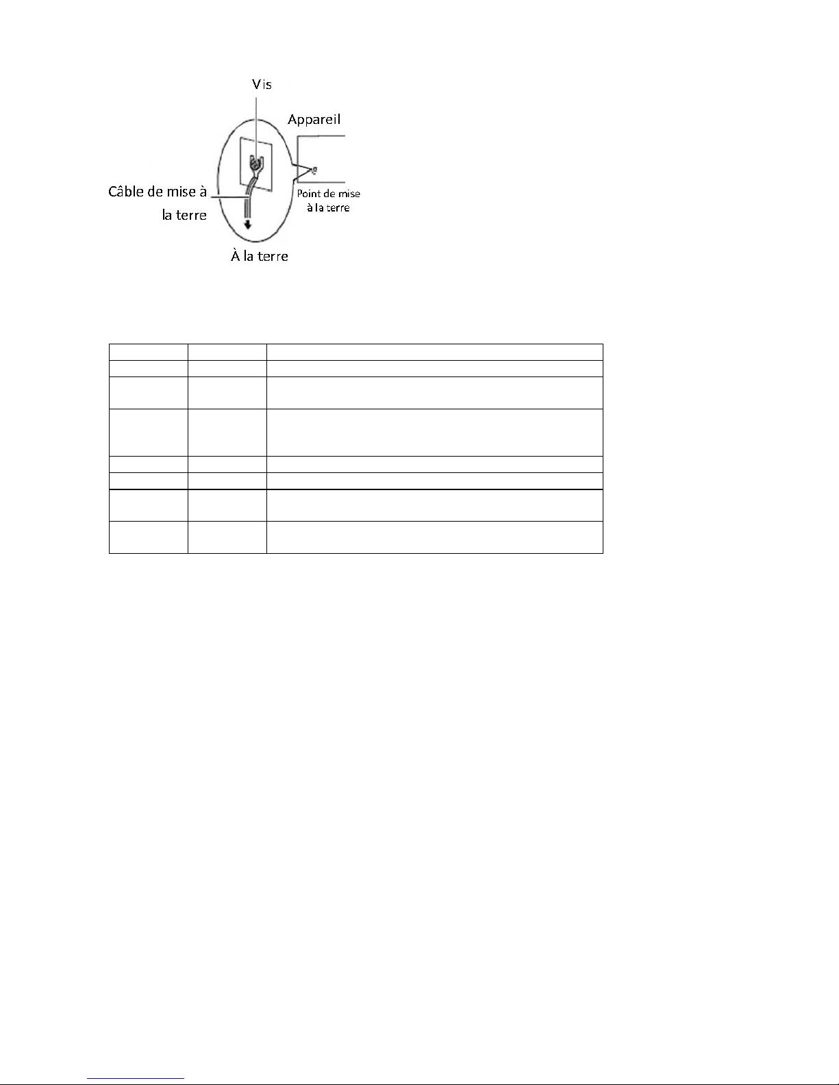
Procédure de mise à la terre pour source
d’alimentation CC Procédure de mise à la
terre pour source d’alimentation CC
Desserrez la vis du terminal de mise à la terre. •
Branchez le câble de mise à la terre à la terre.•
L’appareil de protection pour la source •
d’alimentation CC doit fournir 30 A de courant.
Cet appareil de protection doit être branché à la
source d’alimentation avant l’alimentation CC.
Page 8
Revision History
Version Date Descriptions
V0.1 2014/11/04 Preliminary
V0.2 2014/11/17 Updated hardware setup
Updated mounting instructions
V0.3 2014/12/10 Updated pin assignments
Modied hardware setups
Added updated LCM instructions
V1.0 2015/06/04 Ocial release
V1.1 2015/07/06 Added BIOS chapter
V1.2 2015/12/09 Removed JVGA pinout
Modied Serial bit per second description in BIOS
V1.3 2016/05/11 Modied power supply/input information
Modied temperature specications
Page 9

Chapter 1:
Introduction
Thank you for choosing Lanner FW-8896. The FW-8896
is an upgrade platform of FW-8895. It delivers many
technological advancements as followed:
Dual Intel® Haswell-EP Xeon® E5-2600 v3 CPUs with •
C612 chipset
Driven by dual Intel® Xeon® E5-2600 v3 CPUs
with C612 chipset (codenamed “Grantley”),
this new platform delivers excellent efficiency
and performance. The architecture of this next
generation platform supports quad-channel
memory, up to 512GB of registered DDR4 RAM and
40 PCIe 3.0 lanes. Regarding the chipset, Intel® C612
PCH (codenamed “Wellsburg”) with ultra peripheral
connectivity supporting multiple PCIe lanes, SATA
ports, USB ports and IPMI/OPMA.
Intel® • QPI® links up to 9.6 GT/s
FW-8896 is built with dual Intel Xeon CPUs and
connected by the latest Intel QPI links up to 9.6 GT/s
to keep latency down to minimal even during heavy
workloads.
Up to Eight Ethernet modules with 64 GbE ports:•
Lanner FW-8896 can fit in up to 8 Ethernet modules,
with a total of up to 64 GbE ports. The appliance also
supports 1/10G RJ-45 or 1/10/40G fiber Ethernet.
NIC modules are available for further expansion
(optional).
Support N+1 hot-swappable cooling fans with smart •
fan control
Cooling fans are essential especially in rackmount
applications. The hot-swappable mechanism allows
easy replacement of worn-out fans to ensure
constant and reliable operations.
Intel• ® Coleto Creek 8925 acceleration engine
The integration of Intel Coleto Creek 8925 delivers up
to 25 Gbps throughput and provides optimal boost
to handle repetitive and large-scale mathematical
loads.
Intel• ® QuickAssist Technology
The Intel Grantley platform comes with Intel
QuickAssist Technology, accelerating security packet
and compression processes.
Watchdog Timer and Gen 2/3 LAN Bypass•
System Specifications
Form Factor 2U Rackmount
Platform
Processor Options
2 x Intel Xeon E5-2600 v3 Series on
LGA2011-R3 (Haswell-EP)
Chipset Intel C612 chipset
BIOS AMI BIOS 128Mb
System
Memory
Technology DDR4 2133 MHz registered DIMM
Max. Capacity 512 GB
Socket 16 x 288-pin DIMM
OS Support
Windows 7, 2008 Server, Linux kernel
2.6 or later
Storage
HDD Bays
For models A/B/C/D:
1 x 3.5” SATA HDD
For models E/F/G/H:
2 x 2.5” SATA HDDs/SSDs
NAND Flash 1 x CFast
Networking
Management Ports
For models A/B/C/D:
1 x RJ45 GbE port
For models E/F/G/H:
2 x RJ45 GbE ports
Bypass
Depending on Ethernet module specications
(support Lanner Gen 3 bypass)
Controllers 2 x Intel® i210AT
Ethernet Modules
up to 8 slim type modules (1xPCIe*8 or
2xPCIe*4)
Console Ports 1 x RJ45 console port
Security Acceleration Intel ColetoCreek 8925
LAN ports
Up to 64 GbE ports, depending on
modules installed
I/O Interface
Reset Button
1 x reset button
Software reset by default
Console 1 x RJ45
USB 2 x USB 2.0
IPMI via OPMA slot
OPMA socket to support IPMI IAC-
AST2300 1x 10/100/GBE
Expansion PCIe
4x PCIe*8 connectors for front NIC
2x PCIe*16 ZD connectors for back-
plane
1x PCIe*8 connector for riser card
Cooling
Processor 2 x CPU heat-sink (Passive)
System
4 x independent hot-swappable cooling
fans with smart fan control
Environmental
Parameters
Temperature
Operating: 0 ~ 40º C
Non-operating: -20~70º C
Humidity (RH)
Operating: 5~90% non-condensing
Non-operating: 5~95% non-condensing
Miscellaneous
LCD Module
1x character type LCM with 4 keypads
(graphic optional)
Watchdog Yes
Internal RTC with Li
Battery
Yes
Physical
Dimensions 438 x 88 x 600, unit:mm
Weight 25 kg
Power Type / Watts
FW-8896A/B/E/F 100-240V~ /47-63Hz
/9-4A
FW-8896C/D/G/H 100-240V~ /47-63Hz
/12-6A
Certicate & Compliance CE Class A, FCC Class A, RoHS
Page 10

Package Contents
Your package contains the following items:
FW-8896 Network Security Platform•
2 power cables•
1 Long Ear Rack mount kit with screws•
1 Console cable•
1 LAN cable (grey)•
Optional:
RC-8896 1A PCIe riser card (RC-8896 1A, brackets, and screws) 2U slide kit•
IPMI Card: IAC-AST2300•
TPM Module: IAC-TPM01A / IAC-TPM01B•
Note: If any components is missing or damaged, please contact your dealer immediately for assistance.
Ordering Information
Compatible Accessories
Models Specifications Chipset
Gen3
Bypass
NCS2-IGM428A 4 x GbE RJ45 Intel i350AM-4 2 pairs
NCS2-IGM428B 4 x GbE RJ45 Intel i350AM-4 N/A
NCS2-IGM806A 8 x GbE RJ45 Intel i350AM-4 4 pairs
NCS2-IGM806B 8 x GbE RJ45 Intel i350AM-4 N/A
NCS2-IGM808A 8 x GbE RJ45 Intel i210AT 4 pairs
NCS2-IGM808B 8 x GbE RJ45 Intel i210AT N/A
NCS2-ISM405A 4 x GbE SFP Intel i350AM-4 2 pairs
NCS2-ISM406A 4 x GbE SFP Intel i350AM-4 N/A
NCS2-ISM802A 8 x GbE SFP Intel i350AM-4 N/A
NCS2-IXM204A 2 x 10G SFP Intel 82599ES N/A
NCS2-IXM205A 2 x 10G SFP Intel 82599ES 1 pair
NCS2-IXM405A 4 x 10G SFP Intel 82599ESPLX8724 N/A
NCS2-IXM407 4 x 10G SFP+ Intel Fortville N/A
NCS2-IQM201 2 x 40G QSFP+ Intel Fortville N/A
FW-8896A 8 Ethernet modules, one internal 3.5” HDD space with DH8925 600W PSU Support upto 2x 95W CPU
FW-8896B 8 Ethernet modules, one internal 3.5” HDD space without DH8925 600W PSU Support upto 2x 95W CPU
FW-8896C 8 Ethernet modules, one internal 3.5” HDD space with DH8925 800W PSU Support upto 2x 130W CPU
FW-8896D 8 Ethernet modules, one internal 3.5” HDD space without DH8925 800W PSU Support upto 2x 130W CPU
FW-8896E 8 Ethernet modules, two external 2.5” HDD Tray with DH8925 600W PSU Support upto 2x 95W CPU
FW-8896F 8 Ethernet modules, two external 2.5” HDD Tray without DH8925 600W PSU Support upto 2x 95W CPU
FW-8896G 8 Ethernet modules, two external 2.5” HDD Tray with DH8925 800W PSU Support upto 2x 130W CPU
FW-8896H 8 Ethernet modules, two external 2.5” HDD Tray without DH8925 800W PSU Support upto 2x 130W CPU
Page 11
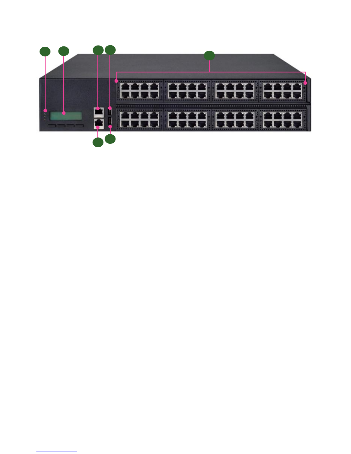
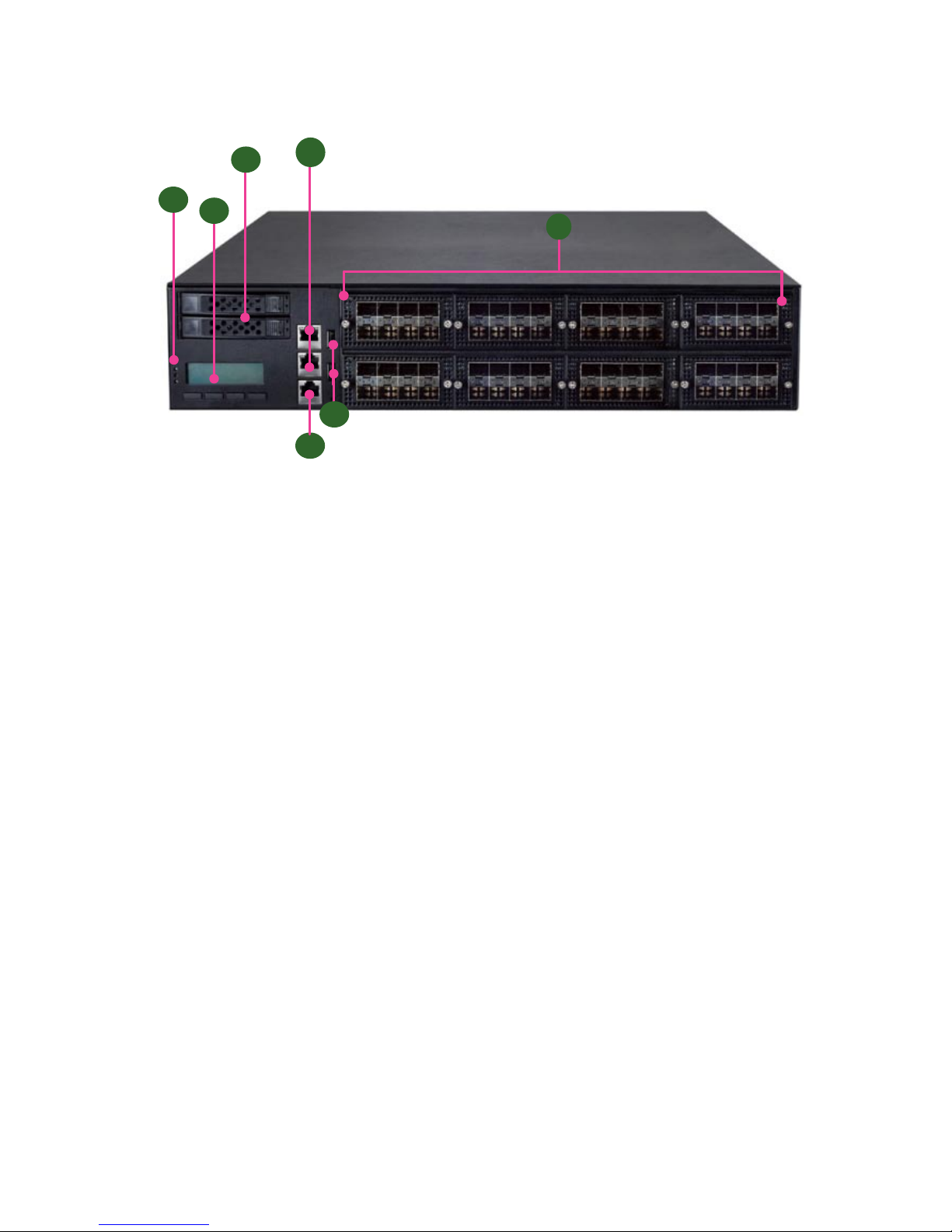
Front Panel Features (FW-8896 A/B/C/D)
F1 Power/Status/HDD LED
Power LED: If the LED is on, it indicates that the system is powered on. If it is off, it indicates that the system is powered
off.
Status LED: This LED indicator is programmable. You could program it to display the operating status with the
behaviors as followed:
If the LED is green, it indicates that the system’s operational state is normal. If it is red, it indicates that the system is
malfunctioning.
HDD: If this LED blinks, it indicates data access activities; otherwise, it remains off.
F2 LCD System Panel
F3 Management Port
F4 Console Port
F5 Reset Switch
F6 Two USB 2.0 Ports
F7 Swappable Ethernet Modules (with LAN bypass model options)
F3
F4
F5
F1
F7
F2
F6
Page 12
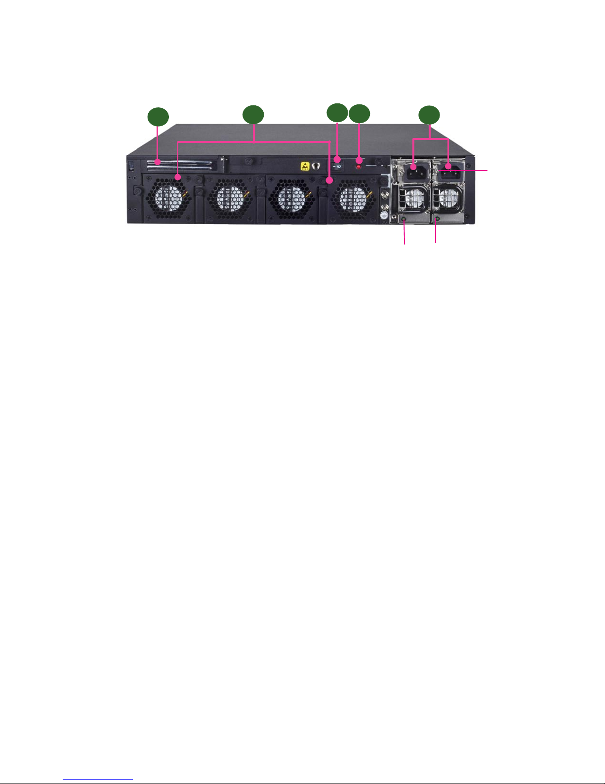
Rear Panel Features (FW-8896 A/B/C/D)
R1 Low Profile PCIe Expansion Slot
R2 4 x Modular Fans
R3 Power Switch
R4 Power Supply Alarm Switch
R5 Redundant Power Supply
R3
R1
R2
R5
R4
PSU latch
screw
PSU LED
Page 13
Front Panel Features (FW-8896 E/F/G/H)
F1 Power/Status/HDD LED
Power LED: If the LED is on, it indicates that the system is powered on. If it is off, it indicates that the system is powered
off.
Status LED: This LED indicator is programmable. You could program it to display the operating status with the
behaviors as followed:
If the LED is green, it indicates that the system’s operational state is normal. If it is red, it indicates that the system is
malfunctioning.
HDD: If this LED blinks, it indicates data access activities; otherwise, it remains off.
F2 LCD System Panel with keypads
F3 2 x External SATA 2.5” drive bays
F4 2 x Management ports
F5 1 x Console port
F6 2 x USB ports
F7 8 x Ethernet NIC modules up to 64GbE (maximum 8 modules)
F3
F6
F5
F1
F7
F2
F4
Page 14

Rear Panel Features (FW-8896 A/B/C/D)
R1 Low Profile PCIe Expansion Slot
R2 4 x Modular Fans
R3 Power Switch
R4 Power Supply Alarm Switch
R5 Redundant Power Supply
R3
R1
R2
R5
R4
PSU latch
screw
PSU LED
Page 15
Chapter 2:
Motherboard Information
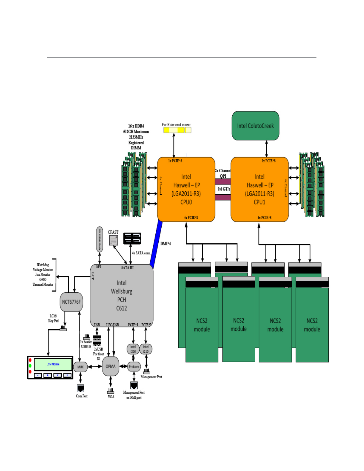
Block Diagram
The block diagram indicates how data flows among components on the motherboard. Please refer to the following
figure for your motherboard’s layout design.
Page 16

Motherboard Layout
The motherboard layout shows the connectors and
jumpers on the board. Refer to the following picture
as a reference of the pin assignments and the internal
connectors.
CFast1
COMB1
JDDR0-3
MGT1
JFAN2
JDDR12-15
CPU Socket
No.1
JVGA1
MGT2
JCOMA1
JOPMA1
J23
JFAN1 JFAN3 JFAN4
ATX3-4
ATX1-2
CPU Socket NO. 2
JLCM1
JUSB2
JUSB1
ATX5
CON3
SATA1-4
OPEN2
JOPEN1
JDDR4-11
J25
JSPIROM1
JTPM1
J80PORT1
JCMOS
J27
JGP1
JRISER1
JPCIESL4
JPCIESL3
JPCIESL2
JPCIESL1
Page 17
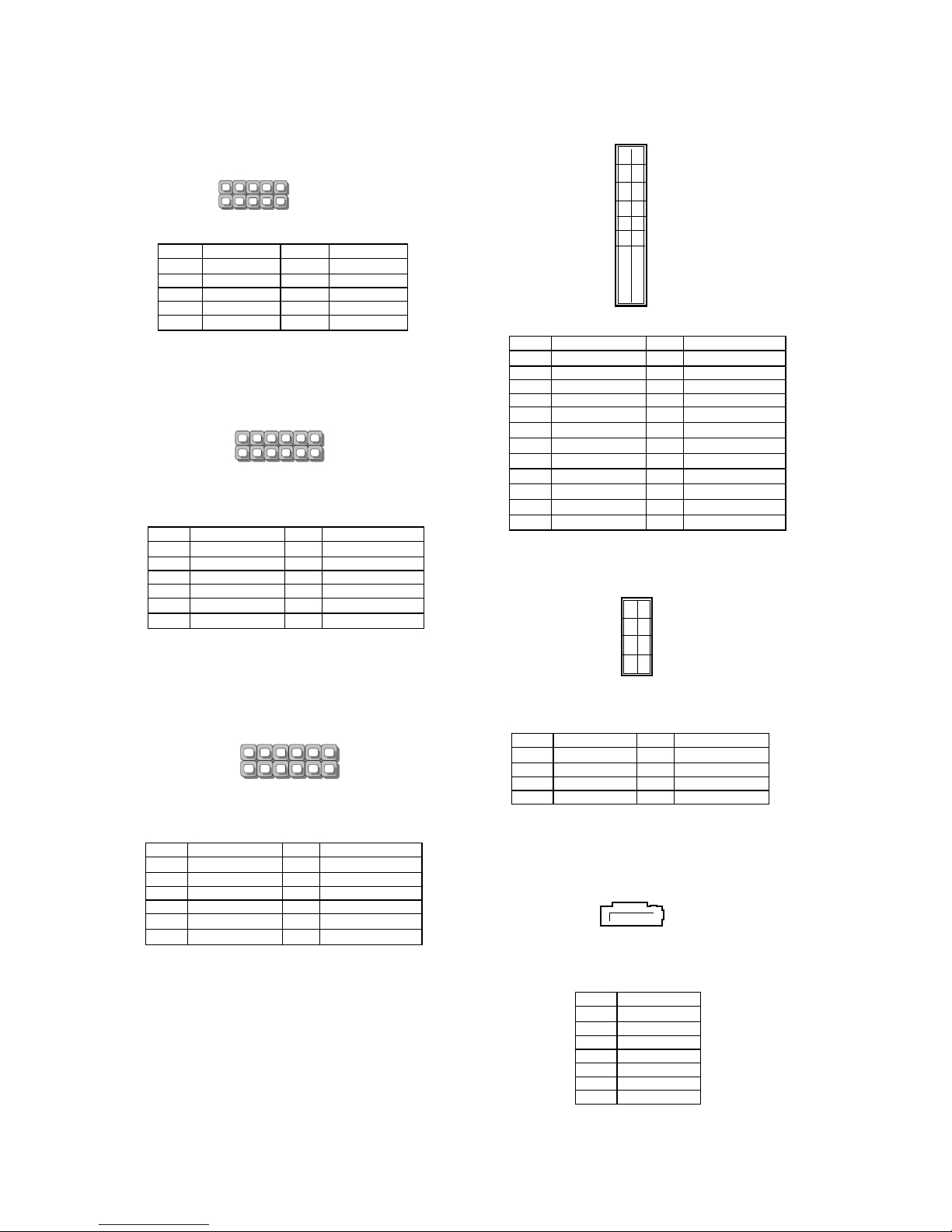
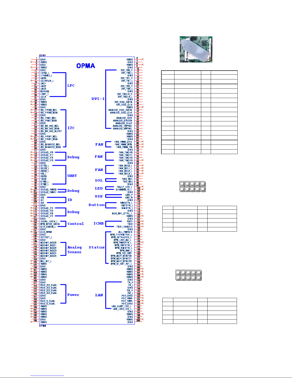
Internal Jumper & Connectors
JLCM1: USB-type front LCD Message Display
Module (LCM).
MGT1: RJ 45 LAN management port connector by
Intel I210 LAN
MGT2: RJ 45 LAN management port connector
Pin Description Pin Description
1 P5V_SB 2 P5V
3 USB20_N5 4
5 USB20_P5 6 HDD_LED#
7 GND 8 GND
9 NTXD2 10 NRXD2
Pin Description Pin Description
1 LAN2_MDX+0 2 LAN2_MDX-0
3 LAN2_MDX+1 4 LAN2_MDX-1
5 LAN2_MDX+2 6 LAN2_MDX-2
7 LAN2_MDX+3 8 LAN2_MDX-3
9 LAN2_100# 10 LAN2_ACTR#
11 LAN2_1000# 12 P3V3_AUX
ATX5: 24-Pin ATX Power Connector
ATX1~4: 8-Pin ATX Power Connector
SATA1~4: SATA Connectors for SATA disk drives
Pin Description Pin Description
1 +3.3V 2 +3.3V
3 +3.3V 4 -12V
5 Ground 6 Ground
7 +5V 8 PSON-
9 Ground 10 Ground
11 +5V 12 Ground
13 Ground 14 Ground
15 Power Good 16 NC
17 Stand-By 5V 18 +5V
19 +12V 20 +5V
21 +12V 22 +5V
23 3.3V 24 GND
23
21
19
1
24
23
20
2
1
3
5
7
2
4
6
8
Pin Description Pin Description
1 GND 2 +12V
3 GND 4 +12V
5 GND 6 +12V
7 GND 8 +12V
Pin Description
1 GND
2 TX_P
3 TX_N
4 GND
5 RX_N
6 RX_P
7 GND
Pin Description Pin Description
1 MGT_MDIP_0 2 MGT_MDIN_0
3 MGT_MDIP_1 4 MGT_MDIN_1
5 MGT_MDIP_2 6 MGT_MDIN_2
7 MGT_MDIP_3 8 MGT_MDIN_3
9 MGT_LAN_100# 10 MGT_LAN_ACT#
11 MGT_LAN_1G# 12 P3V3_AUX
SATA1
7 6 5 4 3 2 1
2
10
9
1
USB_LCM
MGT1
11
12
2
1
MGT2
11
12
2
1
Page 18
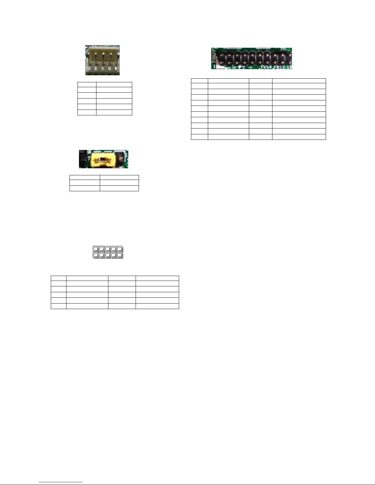
JFAN1~4: 5-Pin FAN Connector.
J27: Jumper for Reset
JUSB1: USB 2.0 internal pin header
Pin Description
1 Ground
2 12V
3 RPM Sense
4 RPM Sense
5 PWM Status
Pin Description
Short Pin 1-2 Hardware reset
Short Pin 2-3 Software reset
JUSB2: USB 2.0/3.0 Internal Connector
Pin Description Pin Description
1 2 USB20_L_P2
3 USB20_L_P3 4 USB20_L_N2
5 USB20_L_N3 6 USBGND02
7 USBGND02 8 USB30_TX2P_C_L
9 USB30_TX1P_C_L 10 USB30_TX2N_C_L
11 USB30_TX1N_C_L 12 USBGND02
13 USBGND02 14 USB30_RX2P_L
15 USB30_RX1P_L 16 USB30_RX2N_L
17 USB30_RX1N_L 18 P5V_USB2
19 P5V_USB2 20
Pin Description Pin Description
1 P5V_USB1 2 P5V_USB1
3 USB20_L_N0 4 USB20_L_N1
5 USB20_L_P0 6 USB20_L_P1
7 USBGND1 8 USBGND1
9 USBGND1 10 USBGND1
2
10
9
1
USB1
Page 19
OPMA1: OPMA interface. The OPMA connector is
for connecting the OPMA card. When the OPMA card is
connected, the management port will comply with the
Intelligent Platform Management Interface (IPMI) standard.
JCFast1: CFast card
JCOMA1: COM PORT Connector
COMB1: COM PORT Internal Connector
Pin Description Pin Description
1 NDCD1 2 NDSR1
3 NRXD1 4 NRTS1
5 NTXD1 6 NCTS1
7 NDTR1 8 NRI1
9 GND 10 FP_RESET_N
Pin Function Pin Function
PC1 Tie to Pin17 S1 GND
PC2 GND S2 SATA_TX_P0
PC3 S3 SATA_TX_N0
PC4 S4 GND
PC5 S5 SATA_RX_N0
PC6 S6 SATA_RX_P0
PC7 GND S7 GND
PC8 LED_CFAST#
PC9
PC10
PC11
PC12
PC13 P3V3
PC14 P3V3
PC15 GND
PC16 GND
PC17 Tie to Pin1
Pin Description Pin Description
1 NDCD2- 2 NDSR23 NRXD2 4 NRTS25 NTXD2 6 NCTS27 NDTR2 8 NRI29 GND 10
2
10
9
1
COMA1
2
10
9
1
COMB1
Page 20
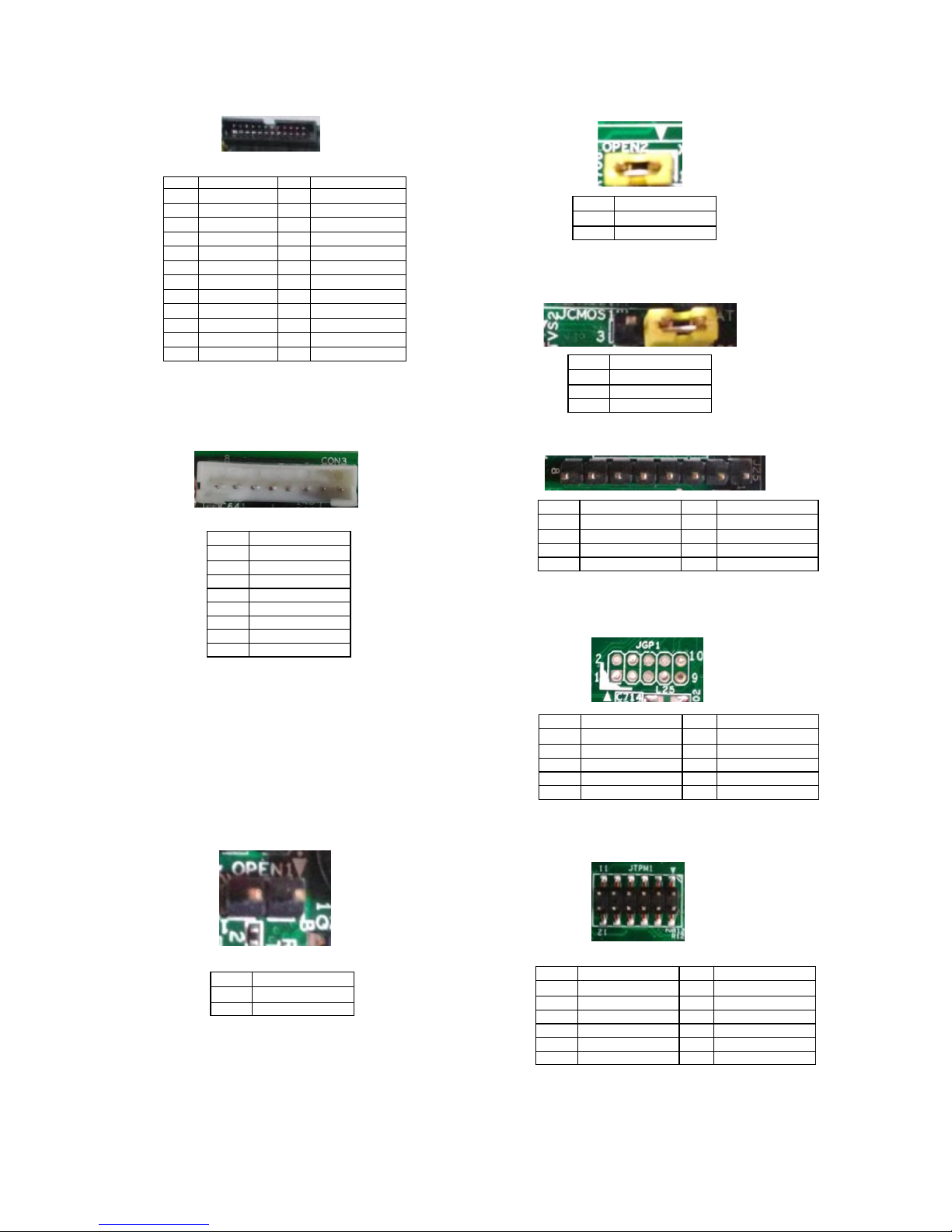
J23: LCM
CON3: PMBUS/TTL
JOPEN1: Chassis Open Detect mainboard protection
jumper. (a short-pin cap will be connected to the top
compartment of the system chassis. When the top
compartment is lifted/removed, the board functions will
be disabled once the jumper cap is lifted along with the
top compartment. This is to protect the board from being
tampered by anyone who remove the top compartment.
Pin Description Pin Description
1 VCC 2 GND
3 P_SLIN_N 4 VEE
5 P_AFD_N 6 P_INIT_N
7 LPD1 8 LPD0
9 LPD3 10 LPD2
11 LPD5 12 LPD4
13 LPD7 14 LPD6
15 LCD 16 VCC
17 KPA1 18 KPA2
19 KPA3 20 KPA4
21 FP_RESET# 22 CTR_GRN
23 CTR_YEW 24 HDD_LED#
Pin Description
1 PSU_TTL1
2 PSU_TTL2
3
4 GND
5
6 PMBUS_CLK
7 PMBUS_DAT
8 PMBUS_ALERT#
Pin Description
1 GND
2 CSOPEN#
JOPEN2: MGT port SEL (IPMI/I210). This is the
management port function selection jumper.
JCMOS: Clear CMOS
J25: Burn CPLD (Complex Programmable Logic Device)
JGP1: External GPIO header
JTPM1: TPM connector
Pin Description
1 MGT_SEL
2 IPMI_DETECT#
Pin Description
1 VRTC
2 PCH_RTCRST#
3 GND
Pin Description Pin Description
1 VCC 5
2 JTAG_PLD_TPO 6 JTAG_PLD_TMS
3 JTAG_PLD_TD1 7 GND
4 8 JTAG_PLD_TCK
Pin Description Pin Description
1 GPO_B_1 6 GPI_B_3
2 GPI_B_1 7 GPO_B_4
3 GPO_B_2 8 GPI_B_4
4 GPI_B_2 9 GND
5 GPO_B_3 10 GND
Pin Description Pin Description
1 IRQ_SERIAL 2 LPC_FRAME#
3 LPC_LAD0 4 CLK_33M_PCI
5 LPC_LAD1 6 VCC
7 LPC_LAD2 8
9 LPC_LAD3 10 VCC
11 PLT_RST# 12 GND
Page 21
Chapter 3:
Hardware Setup
Preparing the Hardware Installation
WARNING:
To reduce the risk of personal injury,
electric shock, or damage to the equipment,
please remove all power connections
to completely shut down the device.
Also, please wear ESD protection gloves
to conduct the steps in this chapter.
Power off the FW-8896 and make sure the power cord 1.
is disconnected from the device.
Loosen the 2 thumbscrews from the rear panel of the 2.
FW-8896 System.
Gently pull the cover backward 3.
Open the cover from the side.4.
unscrew the thumbscrews on
the back and open the top
cover.
2
1
3
4
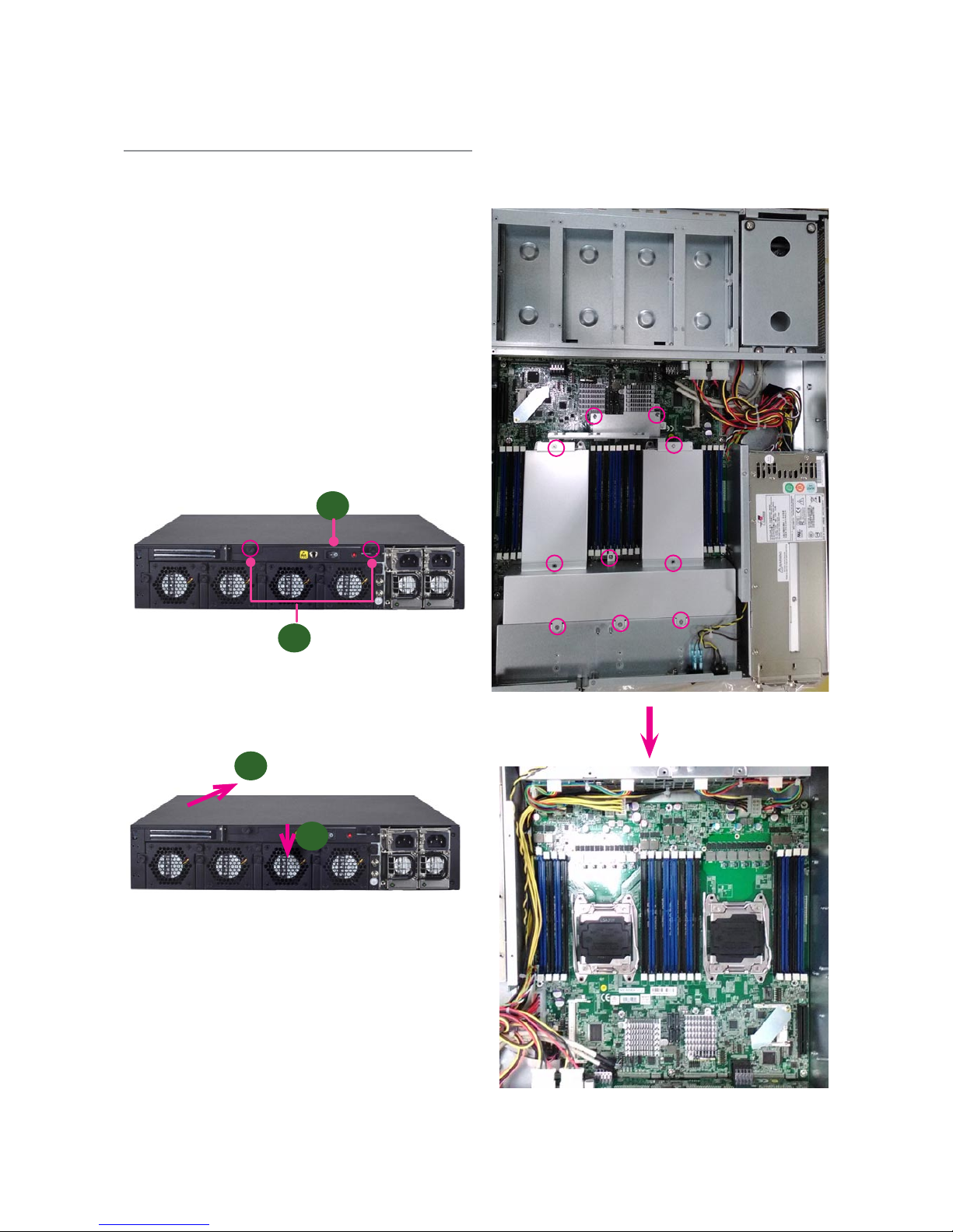
5. Removed the screws circled in the image below to
take away the protection cover for CPUs and other
connectors.
Page 22
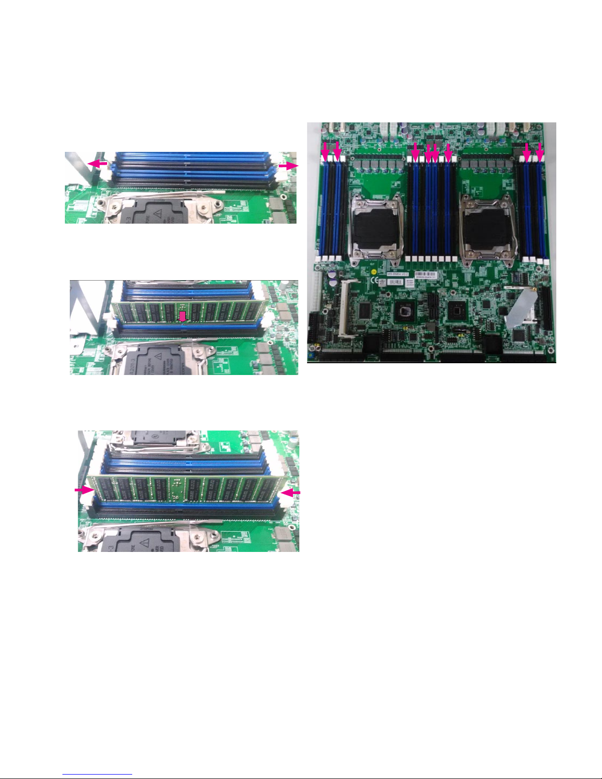
Installing the System Memory
The motherboard supports DDR4 registered DIMM
memory for heavy-duty operations. Please follow the
steps below to install the DIMM memory modules.
Power off the system.1.
Pull open the DIMM slot latches2.
Align the DIMM module and make sure the notches 3.
of the module aligned with the socket keys in the slot.
Insert the module into the slot until it’s firmly seated.4.
The motherboard of FW-8896 is designed with 16 DDR
DIMM sockets. For users without 16 modules to ll up all
the sockets, it is recommended to start by the blue ones
for optimal performance.
Page 23
Installing the CFast Card
FW-8896 provides one CFast slot. Follow the procedures
below for installing a CFast card.
Locate the CFast socket.1.
Remove the protection cover.2.
Insert a CFast card until completed seated.3.
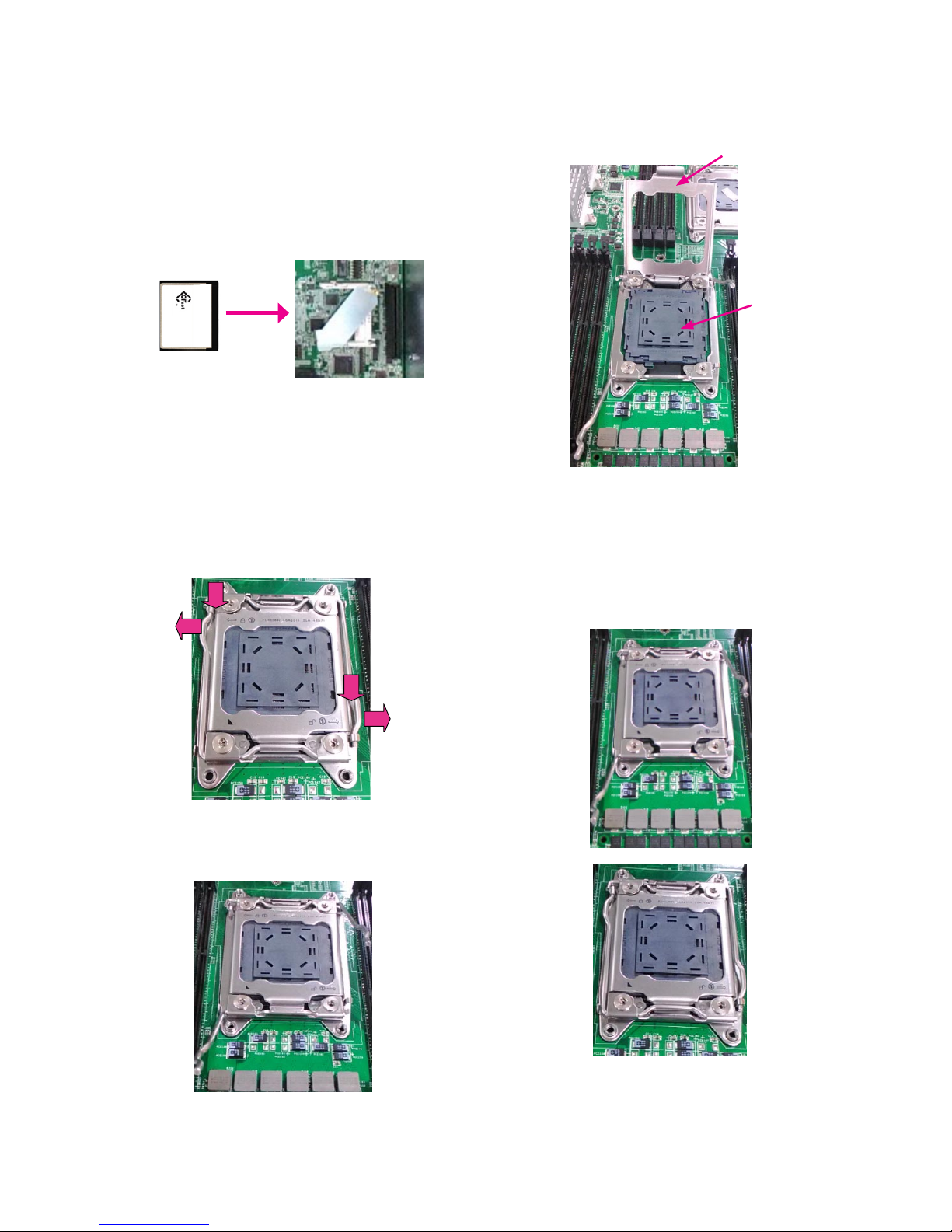
Installing CPU and the Heat Sink
Follow the procedures below for installing a CPU
1. Locate the CPU socket(s)
2. Press the left load lever down, move it out of the
retention tab. Then, do the same to the right. There are
two levers for each CPU socket.
3. Lift the load levers.
Press down
Press down
4. Open the load plate and also the protective cap.
5. Align the CPU and the notch on the socket. The CPU
should fit perfectly into the socket. Note that the CPU
fits in the socket in only one direction.
6. Put the protective cap onto the CPU. Close the load
plate and push the load lever to lock it back to the
retention tab.
Load plate
Protective cap
Page 24
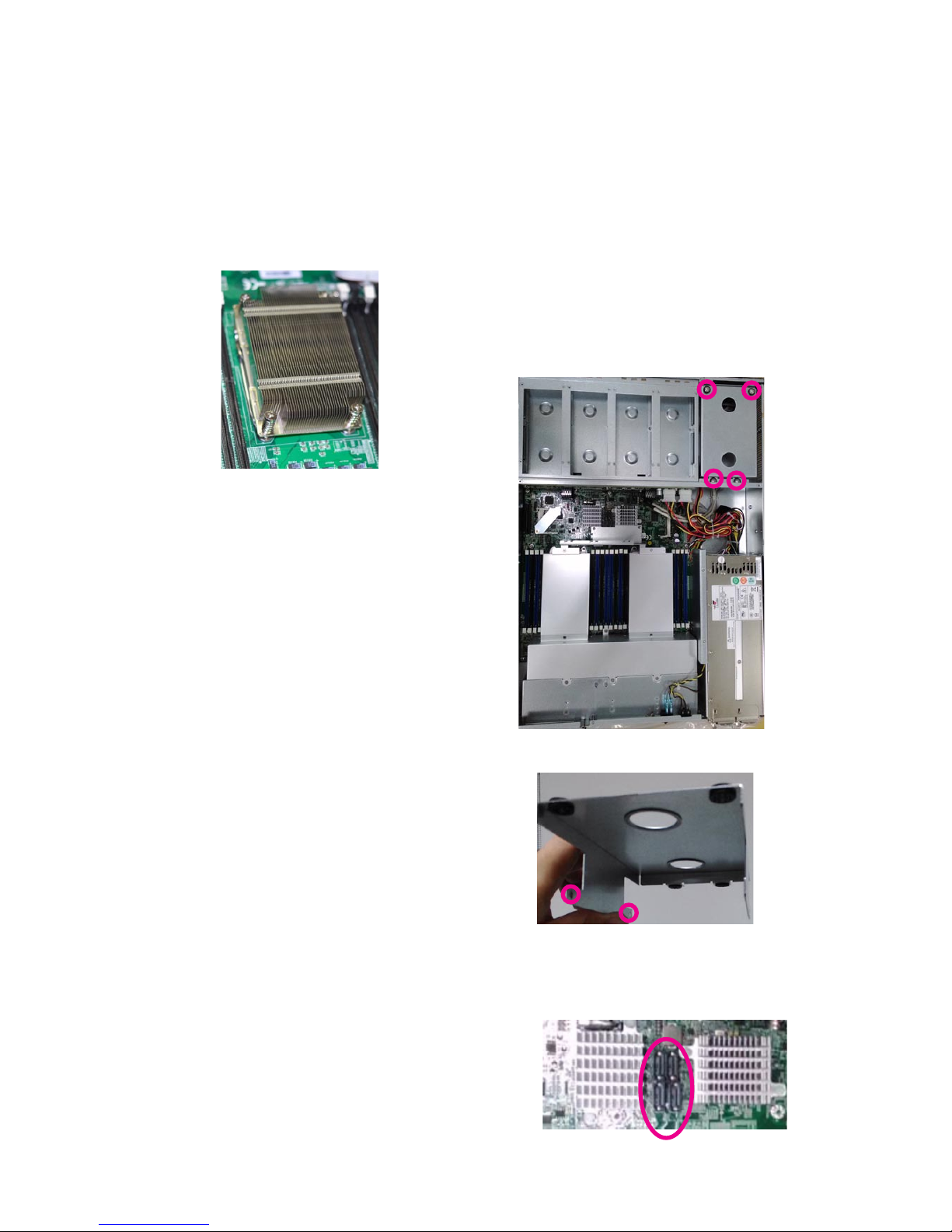
7. Put the heat sink on the installed CPU and match the
screws with the screw holes on the board. Fasten two
screws which are opposite to each other at a time and
then the other two. It is easier this way to avoid the force
of spring.
Place the heat sink cover on top of the installed heat sink
and fasten it with screws on the chassis.
Note:
If you have only one CPU, install it on the left 1.
side (CPU socket No.1with the front panel
facing you). Failure to do so will result in boot
failure .
To protect the CPU socket pins, retain the CPU 2.
cap when the CPU is not installed.
Installing the Disk Drive(s)
Please be noted that FW-8896 series comes with two
different HDD/SSD designs. FW-8896 (A/B/C/D) is built
with one 3.5” HDD/SSD slot (HDD preferred) while the
E/F/G/H models come with two externally accessible 2.5”
HDD/SSD drive bays. The following will discuss all the disk
drive installation procedures based on their HDD/SSD
designs.
For FW-8896 A/B/C/D
FW-8896 A/B/C/D supports one 3.5” HDD/SSD. Please
follow the guidelines below.
As illustrated below, the disk drive bay is located at 1.
the top right corner inside FW-8896. Loosen and
remove the 4 screws circled.
2. Take the tray out and use the mounting holes on both
sides to secure HDD.
3. Use SATA cables to connect both the HDD and the SATA
connectors on the motherboard.
Page 25
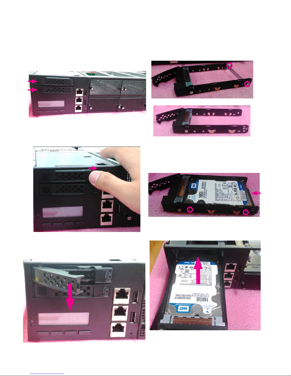
For FW-8896 E/F/G/H
FW-8896 E/F/G/H supports 2 x 2.5” HDDs/SSDs. Please
follow the guidelines below.
1. Locate the two externally accesible 2.5” SATA drive bays
on the front panel.
2. Put your finger on the tab and push it to the right, as
illustrated in the image below.
3. The cage of the drive bay will be released. The drive bay
can be taken out.
4. Remove the two screws circled in the image below to
remove the slim bar.
5. Insert your SATA 2.5” HDD/SSD into the tray. Remember
to put the storage device in the right direction as
illustrated below. Align the drive with the 4 screw holes.
Secure your disk drive with 4 screws.
6. Insert the drive with the tray into the external drive bay
until it’s firmly seated.
SATA Connector
Page 26
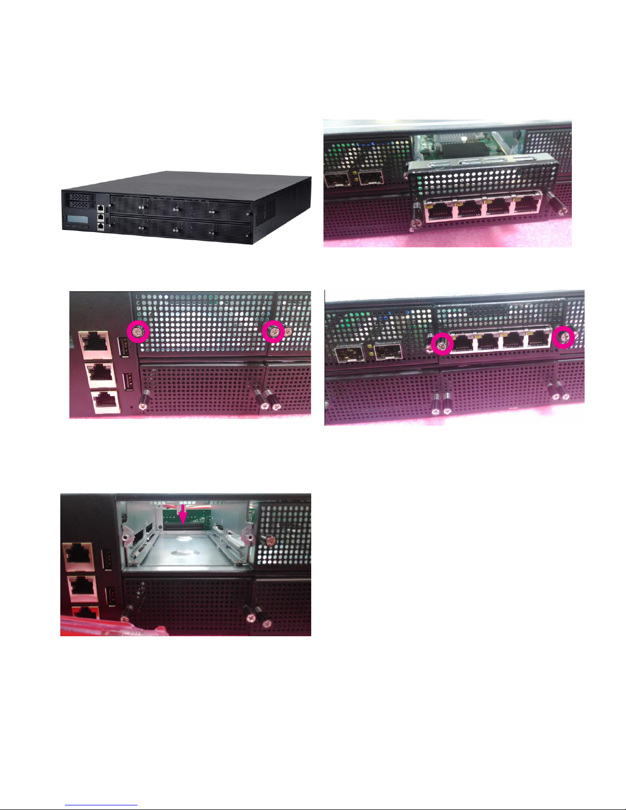
Installing the NIC Modules
FW-8896 series comes with 8 NIC Ethernet module slots
for network bandwidth expansion. Please follow the steps
for installation.
1. Select a NIC Ethernet module slot.
2. Rotate and loosen the two lock-screws.
3. Remove the door and aim at the PCIe socket for module
insertion.
4. Insert your NIC Ethernet module. (Note: the module
shown in the image below is for reference only).
5. Once the module is firmly seated, rotate and tighten the
two lock-screws.
Page 27

Replacing the Power Supply Units
Power supply units may wear down eventually. Please
be noted that FW-8896 series supports 600W/800W
depending on the ordering preferences. Please prepare
the power supply units matching this capacity.
1. Locate the power supply units.
2. Loosen one of the lock-screws depending on which
power supply unit is to be replaced.
3. Hold the handle and pull it out.
4. Locate the internal connector of the power supply unit.
5. Insert a new power supply unit.
6. Remember to tighten the lock-screws.
Page 28

Replacing the Cooling Fans
Cooling fans may wear down eventually. Please refer to
the steps below for replacing cooling fans.
1. Locate the cooling fans at the rear panel.
2. Loosen the two lock-screws of the fan you would like to
replace.
3. Hold onto the two lock-screws and pull it out.
4. Remove the 4 screws that secure the fan.
5. Remove the 4 screws that enclose the fan.
6. Take the fan connector out of the enclosure.
Page 29

7. Take the worn cooling fan out.
8. When using a new cooling fan, simply reverse the previous
steps to install the fan back onto the enclosure and the system.
Page 30

Rack Mounting
Installation Precautions:
Elevated Operating Ambient - If installed in a closed 1.
or multi-unit rack assembly, the operating ambient
temperature of the rack environment may be greater
than room ambient. Therefore, consideration should be
given to installing the equipment in an environment
compatible with the maximum ambient temperature
(Tma) specified by the manufacturer.
Reduced Air Flow - Installation of the equipment in 2.
a rack should be such that the amount of air flow
required for safe operation of the equipment is not
compromised. Mechanical Loading - Mounting of the
equipment in the rack should be such that a hazardous
condition is not created due to uneven mechanical
loading.
Circuit Overloading - Consideration should be given to 3.
the connection of the equipment to the supply circuit
and the effect that overloading of the circuits might
have on over-current protection and supply wiring.
Appropriate consideration of equipment nameplate
ratings should be used when addressing this concern.
Reliable Earthing - Reliable earthing of rack-mounted 4.
equipment should be maintained. Particular attention
should be given to supply connections other than
direct connections to the branch circuit (e.g. use of
power strips).”
CAUTION :
Slide/rail mounted equipment is not to be used as a
shelf or a work space.
Beginning Rackmount Installation
1. Check the package contents. The supplied mounting
kit shall include the following items:
2 x 438mm Slide-Rails
1 x pack of screws
Attaching the Inner Brackets to the Chassis
2. Turn a slide rail upside down and release the inner
bracket.
3. Slide the inner bracket all the way up to end of the
slide-rail assembly. You may hear a “click” sound.
4. Push the white slide-rail lock outwards as the arrow of
direction below. Then pull the inner bracket out of the
slide-rail assembly.
5. Release the inner bracket as shown below.
6. Align the inner bracket to the side of the chassis and
make sure the screw-holes are matched. Then secure the
bracket onto the chassis with provided screws.
7. Repeat Steps 1 to 5 for another slide-rail and attach its
inner bracket onto another side of the chassis.
Page 31

Installing Slide Rails
1. In the previous section, you have already detached the
inner brackets and attached them onto the chassis of
your purchased model. By now, you shall install the sliderail assemblies onto the rack.
As the image below, this slide-rail kit does NOT require
screw-xing. Simply aim at 3 available screw holes on the
rack-front and lock it by clipping the slide-rail assembly to
the rack-front as shown in the image below. You should
hear a “click” sound once it is rmly attached.
2. For the rear rack installation, also aim at 3 available
holes and click the slide-rail assembly onto the rear rack.
Click
3. Repeat Step 1 and 2 for another slide-rail assembly in
order to install in onto the rack.
Page 32

Install Applicable Model Onto the Rack
Reminder: it is strongly recommended to carry out this
procedure with two or three persons.
1. Hold the applicable model with its front facing you, lift
the chassis and gently insert the model by aligning with
the slide-rail assemblies, as shown in the image below.
Then push the model as far as possible.
2. Simultaneously push the release tabs on both sides in
the arrow of direction below, while pushing the appliance
into the end of the rack.
Caution: the appliance will be locked during the half way
of sliding-in if the release tabs are not pushed.
3. Completed.
4. To slide the appliance out, gently pull it outwards.
Then, press the slide-rail locks on both side and slide the
appliance out.
Notes: the process of sliding-in and sliding-out should be
smooth. If not, please adjust the mounting tips.
Page 33

Chapter 5:
BIOS Setup
To enter the BIOS setup utility, simply follow the steps below:
1. Boot up the system.
2. Press <Delete> during the boot-up if you connect a keyboard to FW-8896. But if you connect a PC to FW-8896
through console USB/Serial connection, then press <Tab>. Your system should be running POST (Power-On-SelfTest) upon booting up.
3. Then you will be directed to the BIOS main screen.
4. Instructions of BIOS navigations:
[<--] [-->]: select a setup screen, for instance, [Main], [Advanced], [Chipset], [Boot], [Security], and
[Save & Exit]
[↑] [↓]: select an item/option on a setup screen
Enter: select an item/option or enter a sub-menu
ESC: exit the current screen
+/- = to adjust values for the selected setup item/option
F1 = to display General Help screen
F2 = to retrieve previous values, such as the parameters configured the last time you had entered BIOS.
F3 = to load optimized default values
F4 = to save configurations and exit BIOS
Notes: the images in the following section are for reference only.
Page 34

Advanced
Use [<--] / [-->] to select [Advanced] setup screen. Under this screen, you may use [↑] [↓] to select an item you
want to configure.
Above 4G Decoding
This option enables or disables 64bit capable devices to be decoded in above 4G address space (only if the
system supports 64bit PCI decoding). You may select “Enabled” or “Disabled”.
Page 35

SRIOV Support
This option enables or disables SRIOV (Single Root I/O Virtualization) support. You may select “Enable” or “Disable”.
NCT6776 Super IO Configuration
Press “Enter” to access configuration sub-menu for super IO chip (NCT6776) parameters.
Page 36

NCT6776 Super IO Configuration - Serial Port 1 Configuration
The super IO chip for this model is NCT6776. You may select Serial Port 1/2 or Parallet port for configurations.
Serial Port 1 Configuration: Serial Port
Once Serial Port 1 is accessed, you may press “Enter” to enable or disable the Serial Port 1 (COMA). Device setting is
fixed as default.
Page 37

Serial Port 2 Configuration: Serial Port
Once Serial Port 1 is accessed, you may press “Enter” to enable or disable the Serial Port 1 (COMB). Device setting is
fixed as default.
Page 38

Parallel Port Configuration
This option allows you to set parameters for parallel port (LPT/LPTE).
Once Parallel Port 1 is accessed, you may press “Enter” to enable or disable the Parallel Port. Device setting is fixed as
default.
Page 39

NCT7904D HW Monitor
This option allows you to view hardware health status.
Page 40

Page 41

Serial Port Console Redirection
This option allows you to configure parameters about serial port console redirection. Press “Enter” to access the submenu.
Console Redirection: select “Enabled” or “Disable” for COM port console redirection. The default is “Enabled”.
Console Redirection Settings: select this item to enter the setting sub-menu.
Page 42

COM Console Redirection Settings
Terminal Type: the emulation configuration. Select “VT100”, “VT100+”, “VT-UTF8” or “ANSI”.
ANSI: Extended ASCII character set
VT100: ASCII character set
VT100+: extends VT100 to support color function keys
VT-UTF8: uses UTF8 encoding to map Unicode characters onto 1 or more
Bits per second: select “9600”, “19200”, “38400”, “57600”, or “115200” for bits per second. The Bps
will determine serial port transmision speed. The speed must be matched on the other side. Long or noisy lines may
require lower speeds.
Page 43

Data Bits: select the value for data bits. In this case, “7” or “8”.
Parity Bits: a parity bit can be sent with the data bits to detect some transmission errors. Select “None”, “Even”, “Odd”,
“Mark” or “Space”.
Page 44

Stop Bits: stop bits indicate the end of a serial data packet. The standard is 1 stop bit. Communication with slow
devices may require more than 1.
Flow Control: flow control can prevent data loss from buffer overflow. When sending data, if the receiving buffers
are full, a “stop” signal can be sent to stop the data flow. You may select “None” or “Hardware RTS/CTS”, depending on
the circumstances.
Page 45

VT-UTF8 Combo Key Support: this option enables/disables VT-UTF8 combination key support for ANSI/VT100
terminals.
Recorder Mode: on this mode, when “Enabled”, only text will be sent. This is to capture terminal data.
Resolution 100 x 31: select “Enable” or “Disable” for extended terminal resolution.
Page 46

Legacy OS Redirection Resolution: select “80x24” or “80x25”. The default for this case is “80x24”.
Putty KeyPad: select Function Key and Key Pad on Putty. You may select “VT100”, “LINUX”, “XTERMR6”, “SCO”, “ESCN”,
or “VT400”.
Redirection After BIOS POST: The settings specify if BootLoader is selected than Legacy console redirection is
disabled before booting to Legacy OS. Default value is “Always Enable” which means Legacy OS console redirection
is always enabled after BIOS.
Page 47

Trusted Computing
This option allows you to configure Trusted Computing Settings.
Configuration - Security Device Support
This option enables or disables BIOS support for security devices, such as TPM module. OS will not show Security
Device. TCG EFI protocol and INT1A interface will not be available.
Note: to enable this function, TPM module must have been installed.
Page 48

USB Configuration
This option allows you to configure USB device Settings.
USB Module Version: displays USB module version
USB Devices: displays USB devices
Legacy USB Support: this function enables or disables legacy USB support. Auto option disables legacy support if no
USB devices are connected. Disable option will keep USB devices available only for EFI applications.
Page 49

XHCI Hand-off: enables or disables XHCI Hand-off function. This is a workaround for operating systems without XHCI
hand-off support. The XHCI ownership change should be claimed by XHCI driver.
EHCI Hand-off: this is a workaround for operating systems without EHCI hand-off support. The EHCI ownership
change should be claimed by EHCI driver.
Page 50

USB Mass Storage Driv: this option allows you to enable or disable USB mass storage driver. The default is
“Enabled”.
Port 60/64 Emulation: this option enables I/O port 60h/64h emulation support. This should be enabled for the
complete USB keyboard legacy support for non-USB aware operating systems.
Page 51

USB transfer time-out: set USB time-out value (1, 5, 10 or 20 seconds) for Control, Bulk and Interrupt transfers.
Device reset time-out: set USB mass storage device Start Unit command time-out (10, 20, 30 or 40 seconds).
Device power-up delay: set the maximum time the device will take before it properly reports itself to the Host
Controller. “Auto” uses default value. For example, it is 100ms as a root port.
Page 52

AMI Virtual CDROM0 1.00: set mass storage device emulation type. “Auto” enumerates devices according to their
media format. Please be noted that optical devices will be emulated as CD-ROM.
AMI Virtual Floppy0 1.00: set mass storage device emulation type. “Auto” enumerates devices according to their media
format. Please be noted that optical devices will be emulated as CD-ROM.
AMI Virtual HDisk0 1.00: set mass storage device emulation type. “Auto” enumerates devices according to their media
format. Please be noted that optical devices will be emulated as CD-ROM.
Page 53

LAN Boot Select
This option allows you to select one of the onboard LAN boot. Press “Enter” to access the sub-menu.
On Board LAN Boot: select “Disabled” or “MGT1”/”MGT2” management port booting priority.
Page 54

IntelRCSetup
Use [<--] / [-->] to select [IntelRCSetup] setup screen. Under this screen, you may use [↑] [↓] to select an item you
want to configure.
RC Revision: displays RC revision information
Numa: enables or disables Non-Uniform Memory Access (NUMA)
IOAT Configuration
Press Enter to access the sub-menu of all IOAT (Intel I/O Acceleration Technology) configuration items.
Page 55

Enable IOAT: enables or disables IOAT devicesSelect. This function allows you to enable Intel I/O Acceleration
Technology which benefits system data flows by reducing CPU overheads. The freed CPU resources will improve
system responsiveness and avoid performance bottleneck.
No Snoop: no snoop enable/disable for each CB device
Page 56

Disable TPH: TLP Processing Hint disable
Relaxed Ordering: relaxed ordering enable/disable.
Page 57

Intel (R) VT for Directed I/O (VT-d) Configuration
This option allows users to configure items of Intel Virtualization Technology for Directed I/O (VT-d). Press “Enter” to
access its sub-menu.
VTd Azalea VCp Optimization:
this option allows you to enable or disable Azalea VCp Optimization.
Page 58

Intel VT For Directed I/O (VT-d): enable or disable Intel Virtualization Technology for Directed I/O (VT-d) by reporting
the I/O device to VMM through DMAR ACPI tables.
Interrupt Remapping: enable or disable VT-d Interrupt Remapping support.
Page 59

Coherency Support (Non-Isoch): enable or disable VT-d Engine Coherency support.
Coherency Support (Isoch): enable or disable Isoch VT-d Engine Coherency support
Page 60

IIO0 Configuration
This function allows users to check PCIe port lane width switch status. Press Enter to access the sub-menu.
Set PCIE Port Difurcation By Present Card Lane: displays PCIe port information and status
Page 61

IIO1 Configuration
This function allows users to check PCIe port lane width switch status. Press Enter to access the sub-menu.
Set PCIE Port Difurcation By Present Card Lane: displays PCIe port information and status
Page 62

Processor Configuration
This function allows users to view and configure options that can change processor settings. Press Enter to access the
sub-menu.
Processor Configuration: displays processor status and information.
Page 63

Hyper-Threading [ALL]: enables or disables Hyper Threading. This is the software method to enable or disable logical
processor threads.
Execute Disable Bit: an Intel hardware-based protection against malicious code. It will detect the memory in which a
code can be executed or not. When enabled, it will prevent certain classes of malicious buffer overflow attacks when
combined with a supporting OS. When disabled, it forces the XD feature flag to always return 0.
Page 64

X2APIC: enables or disables extended APIC support.
AES-NI: enables or disables AES-NI (Advanced Encryption Standard - New Instruction) support.
Page 65

PCH Configuration
This function allows users to view and configure PCH settings. Press Enter to access the sub-menu.
PCH State after G3: select S0/S5 for ACPI state after a G3. The default is “Last State”.
Page 66

PCH SATA Configuration
Press Enter to access items for SATA devices and settings.
SATA Controller: enables or disables SATA controller
Page 67

Configure SATA as: this item identifies whether the SATA port is connected to a SSD and HDD. Select IDE, AHCI or
RAID. The default is “AHCI”.
SATA Port 0: displays status of SATA port 0
Software Preserve: displays information of Software Preserve
Port 0: enable or disable this SATA port
Page 68

Hot Plug: designates this port as hot pluggable
Spin Up Device: if enabled for any of ports, Staggered Spin Up will be performed and only the drives which have this
option enabled will spin up at boot. Otherwise all drives spin up at boot.
Page 69

SATA Device Type: identifies the SATA port is connected to SSD or HDD.
SATA Port 1: displays status of SATA port 0
Software Preserve: displays information of Software Preserve
Port 1: enable or disable this SATA port
Page 70

Hot Plug: designates this port as hot pluggable
Spin Up Device: if enabled for any of ports, Staggered Spin Up will be performed and only the drives which have this
option enabled will spin up at boot. Otherwise all drives spin up at boot.
Page 71

SATA Device Type: identifies the SATA port is connected to SSD or HDD.
SATA Port 2: displays status of SATA port 0
Software Preserve: displays information of Software Preserve
Port 2: enable or disable this SATA port
Page 72

SATA Port 2 DevSlp: enable or disable SATA Port 2 DevSlp (Device Sleep). Board rework for LP needed before enable
this option.
Hot Plug: designates this port as hot pluggable
Page 73

Notes:
The BIOS of FW-8896 supports SATA configurations up to 6 ports (SATA port 0~5). Only SATA port 2 is programmed
with SATA Device Sleep feature.
Therefore, SATA port 3~6 all share the same configurable items as desribed for SATA port 0~2.
Spin Up Device: if enabled for any of ports, Staggered Spin Up will be performed and only the drives which have this
option enabled will spin up at boot. Otherwise all drives spin up at boot.
SATA Device Type: identifies the SATA port is connected to SSD or HDD.
Page 74

PCH USB Configuration
Press Enter to access items for USB configurations.
xHCI Mode: offers modes of operation of xHCI controller. You may select “Smart Auto”, “Auto”, “Enabled” or “Disabled”.
Page 75

Security
Use [<--] / [-->] to select [Security] setup screen. Under this screen, you may use [↑] [↓] to select an item you
want to configure.
Administrator Password: set administrator password. Once set, then this only limits access to Setup and is only
asked for when entering Setup.
User Password: set user password. Once set, then this is a power-on password and must be entered to boot or enter
Setup. In Setup, the user will have Administrator rights.
Page 76

Boot
Use [<--] / [-->] to select [Boot] setup screen. Under this screen, you may use [↑] [↓] to select an item you
want to configure.
Boot Configuration
Setup Prompt Timeout: number of seconds to wait for setup activation key. “65535 (0xFFFF)” means indefinite
waitings.
Bootup Numlock State: select the keyboard “Numlock” state
Page 77

Quiet Boot: this option allows you to enable or disable “Quiet Boot”. The default is “Disabled” based on Intel’s server
environment setting.
Boot Option #1: set devices as boot option #1
USB Device BBS Priorities: set USB device BBS priorities
Page 78

Save & Exit
Use [<--] / [-->] to select [Save & Exit] setup screen. Under this screen, you may use [↑] [↓] to select an item you
want to configure.
Save Changes and Exit: exit system setup after saving the configuration changes
Discard Changes and Exit: exit system setup without saving the configuration changes
Save Changes and Reset: reset the system after saving the configuration changes
Discard Changes and Reset: reset the system without saving the configuration changes
Save Options
Save Changes: save the configuration changes
Discard Changes: discard all the configuration changes
Restore Defaults: restore to factory default setting
Save as User Defaults: save changes as the new user default
Restore User Defaults: restore the user default
Boot Override
AMI Virtual CDROM0 1.00
Page 79

Appendix A:
Programming Watchdog
Timer
A watchdog timer is a piece of hardware that can be
used to automatically detect system anomalies and reset
the processor in case there are any problems. Generally
speaking, a watchdog timer is based on a counter that
counts down from an initial value to zero. The software
selects the counter’s initial value and periodically restarts
it. Should the counter reach zero before the software
restarts it, the software is presumed to be malfunctioning
and the processor’s reset signal is asserted. Thus, the
processor will be restarted as if a human operator had
cycled the power.
For sample watchdog code, see watchdog folder on the
Driver and Manual CD
To execute the sample code: enter the number of
seconds to start count down before the system can be
reset. Press start to start the counter and stop to stop the
counter..
Dwd_tst --swt xxx (Set Watchdog Timer 1-255 seconds)
wd_tst[*] --start (Start Watchdog Timer)
wd_tst --stop (Stop Watchdog Timer)
For sample watchdog code, see watchdog folder on the
Driver and Manual CD
Appendix B:
Setting up Console
Redirections
Console redirection lets you monitor and configure a
system from a remote terminal computer by re-directing
keyboard input and text output through the serial port.
This following steps illustrate how to use this feature. The
BIOS of the system allows the redirection of console I/O
to a serial port. With this configured, you can remotely
access the entire boot sequence through a console port.
Connect one end of the console cable to console 1.
port of the system and the other end to serial port of
the Remote Client System.
Configure the following settings in the BIOS Setup 2.
menu:
BIOS > Advanced > Remote Access Configuration >
Serial Port Mode > [115200, 8 , n ,1 ]
Configure Console Redirection on the client system. 3.
The following illustration is an example on Windows
platform:
A. Click the start button, point to Programs > a.
Accessories > Communications and select Hyper
Terminal.
B. Enter any name for the new connection and b.
select any icon.
Click OK.c.
From the “Connect to”. Pull-down menu, select the d.
appropriate Com port on the client system and
click OK.
Select 115200 for the Baud Rate, None. for Flow e.
contorl, 8 for the Data Bit, None for Parity Check,
and 1 for the Stop Bit.
Page 80

Appendix C:
Programming Generation
3 LAN Bypass
The bypass function is used to link two independent
Ethernet ports when the system crashes or powers
off. This means if your system is equipped with a LAN
Bypass function, a condition in your system will not
interrupt your network traffic. Different from the previous
two generations (Gen1 and Gen2), the Lanner Bypass
Gen 3 employs a programming method to control the
bypass function by software. There are typically two
communication status for the bypass function, one is
“Normal” and another is “Bypass” status. Furthermore, the
Lanner Bypass software is capable to control the bypass
status in the following 3 instances.
When the system powers off, it can be forced to 1.
enable the LAN Bypass function .
When the system is in the just-on state which is a 2.
brief moment when it powers up .
When the system is running3.
Please refer to the LAN_Bypass_Watchdog folder on the
Driver and Manual CD.
And the Lanner bypass possess the following features:
Communication through SMBUS (I2C)1.
Independent bypass status control for each pair up to 2.
a total of 4 pairs
Lanner Bypass Modules can bypass systems Ethernet 3.
ports on a host system during three instances: Just-on
(Just-on is the brief moment when the internal power
supply turns on and booting process starts), system
off, or upon software request (during run-time).
Software programmable bypass or normal mode4.
Software programmable timer interval:5.
- JUST-ON watchdog timer, used during JUST-ON, has
timer setting of 5~1275 seconds of timer interval.
- Run-Time watchdog timer, used during run-time, has
setting of 1~255 seconds of timer interval.
Multiple Watchdog Timers:6.
-Two for run-time: It is designed to give you a more
variety of controls of the bypass on port basis. By
using dedicated watchdogs for different pairs of
bypass, you have the flexibility to manage the bypass
status for them differently.
-One for just-on: It is designed to give you the
precise control of the bypass during this phase. You
can use this timer to delay enabling the bypass in
just-on state.
For sample LAN bypass code and the Bypass Manual, see
the LAN_Bypass folder on the Driver and Manual CD or
the Lanner Support Website at http://www.lannerinc.com/
download-center/. And browse the download center and
look for Lanner LAN Bypass Watchdog User Manual under
the Accessories folder.
Fro a description of the physical LAN ports equipped
with this function, refer to Front Panel Features in Chapter
1 Introduction.
Page 81

Appendix D:
Programming the LCM
The LCD panel module (LCM) is designed to provide
real-time operating status and configuration information
for the system. For sample LCM code, see LCM foler in
the Driver and Manual CD. The driver and the program
library can also be found in the folder.
The system supports the following 2 kinds of LCM:
Parallel Text-based LCM: The LCM connects to the •
motherboard’s parallel port. The LCD screen can
display 2 lines, 16 (or 20) characters per line.
USB and Serial Text or Graphic-based LCM: Our next •
generation LCM. Lanner engineers design a common
source code to be deployed on these two differently
interfaced LCM modules. Jumpers are used to select
between text and graphic types. See next section.
For Parallel Text-based LCM
Build
To build program source code on Linux platform, please
use the following steps as a guideline:
1. Extract the source file:
# tar -xzvf plcm_drv_v0XX.tgz
(0XX is the version of the program.)
2. Change directory to the extracted folder:
# cd plcm_drv_v0XX
(0XX is the version of the program.)
Note: Apply our Parallel Text-based LCM to the
environment of virtualization, please use the version 013
or above of the program.
3. Type make to build source code:
# make
After compiling, the executable programs (plcm_test,
plcm_cursor_char, ppdev_test, Test) and the driver
(plcm_drv.ko) will appear in the program’s folder.
Note: The OS supported by Parallel Text-based LCM
function includes platforms based on Linux Kernel series
2.4.x, Linux Kernel series 2.6.x and Linux Kernel series
3.0.x or above.
Install
Install the driver and create a node in the /dev directory
by:
#insmod plcm_drv.ko
#mknod /dev/plcm_drv c 248 0
Note:
If you cannot install the driver,
check whether you have enabled the
parallel port in the BIOS setting .
Once the message of “insmod: error
inserting ‘plcm_drv.ko’: -1 Input/output
error” appears, please check that whether
the major number is repeated or not.
The major number needed with the
mknod command varies with different
software versions; please look up
the Readme file for this value.
Execute
This section contains sample executable programs that
you could test on your platform. It demonstrates some
useful functionality that the LCM provides. Note that the
installation needs to be completed before proceeding
with these executions.
To execute, run the command:
#./plcm_test
Backlight Off/On turning off/on the backlight of the
LCM display
Display Off turning off the LCM display
Cursor Off/On NOT showing/showing the cursor on the
LCM display
Blinking off/On turning off/on the cursor blinking
Writing “Lanner@Taiwan” displaying the specific
sentences
Reading “Lanner@Taiwan” reading the specific sentence
CGram Test displaying the user-stored characters
Keypad Testing Get the keypad input: the 1st button is
read in as Left, the 2nd button is read in as Up, the 3rd
button is read in as Right, and the 4th button is read in as
Down)
Page 82

Corresponding Commands for plcm_test
You can directly input the specic command to have its
corresponding function worked on your LCM. This
will be much more convenient once you would like to
merely execute the keypad testing.
-On
— Turn on the backlight of the LCM display.
— To execute, please type:
#./plcm_test -On
-O
— Turn o the backlight of the LCM display.
— To execute, please type:
#./plcm_test –O
-LCM1
— Writing “Lanner@Taiwan” in line1.
— To execute, please type:
#./plcm_test -LCM1
-LCM2
— Writing “2013-11-05” in line 2.
— To execute, please type:
#./plcm_test -LCM2
Keypad
— Get the keypad input: the 1st button is read in as Left,
the 2nd button is read in as Up, the 3rd button is read
in as Right, and the 4th button is read in as Down.
— To execute, please type:
#./plcm_test -Keypad
Commands for plcm_cursor_char
This Run this command for cursor shift & single text
update
# ./plcm_cursor_char
Please read the options below
Insert line select Item 1 to set the starting line as either
line 1 or line 2
Move cursor right select Item 2 to move the cursor to
the right
Move cursor left select Item 3 to move the cursor to the
left
Add a char select Item 4 to display a character on the
LCM screen
Clean display select Item 5 to clear up the LCM display
Leave select Item 6 to exit the program
Test
This program is a testing script and runs through the
following procedures in sequence:
—rmmod plcm_drv (remove the kernel mode driver
module)
— insmod plcm_drv.ko (install the kernel mode
driver module)
— ./plcm_test (execute the driver testing program)
— ./plcm_test -stop (stop executing the driver testing
program)
— rmmod plcm_drv (remove the kernel mode driver
module)
To execute, please type:
#./Test
Virtualization Implemented by Parallel
Port Pass Through
By the utilization of the parallel port pass through,
the Parallel Text-based LCM implements the following
three kinds of virtualization in the Guest OS.
- QEMU/KVM
- Xen
- VMWare Player
Here, we take the Fedora 20 x86_64 operation system
for instance to explain 3 virtualization respectively for
parallel port pass through. Use the procedures listed
below for step-by-step instructions separately based
on your case.
In case of QEMU/KVM or Xen, please use the following
steps as a guideline to implement the virtualization :
(1) Make sure that the Guest OS has been installed.
(2) Add the following 4 lines into the xml file (for
example, add to
/etc/libvirt/qemu/<yourvirtualmachine>.xml in linux
KVM) :
<parallel type=’dev’>
<source path=’/dev/parport0’/>
<target port=’0’/>
</parallel>
Page 83

(3) Open a terminal in the Guest OS and then issue the
following commands to install linux kernel drivers.
# modprobe parport
# modprobe parport_pc
# modprobe ppdev
(4) Check that whether the /dev/parport0 exists or
not. You may not find proper /dev/parport0 in the
device list, please reconfirm the setup of xml file in the
Guest OS.
(5) Reboot the Guest OS.
Note: It is necessary for you to insmod parport.ko,
parport_pc.ko and ppdev.ko linux kernel drivers in
virtualization environment before executing the
ppdev_test testing program.
In case of VMWare Player, please use the following
steps as a guideline to implement the virtualization:
(1) Make sure that the Guest OS has been installed.
(2) To set up the parallel port pass through, please
enter VMWare Player’s --> Virtual Machine Setting -->
VMWare Player’s setting page to select /dev/parport0
as parallel port device.
(3) Open a terminal in the Guest OS and then issue the
following commands to install linux kernel drivers.
# modprobe parport
# modprobe parport_pc
# modprobe ppdev
4) Check that whether the /dev/parport0 exists or not.
You may not find proper /dev/parport0 in the device
list, please reconfirm the setup of VMWare Player’s
setting page described in Step 2.
(5) Reboot the Guest OS.
Note: It is still necessary for you to insmod parport.
ko, parport_pc.ko and ppdev.ko linux kernel drivers
in virtualization environment before executing the
ppdev_test testing program.
Page 84

Appendix E:
On Linux
Follow these instructions when installing the Intel®
LAN controller base driver for the in Red Hat® and Linux
operating system.
Insert the motherboard/system support CD to the 1.
optical drive and mount the optional drive in the
Linux platform.
Copy the base driver tar file from the motherboard/2.
system support CD to the directory of your local hard
disk. The Intel® LAN driver for Linux OS is located in
the following directory:
\Driver\LAN_Driver\PRO1000\LINUX. The name format
of driver file is “e1000-<Version>.tar.gz”. For example:
the file name of driver version 7.0.38 is “e1000-7.0.38.
tar.gz”.
Untar/unzip the archive, where <x.x.x> is the version 3.
number for the driver tar file:
tar zxf e1000-<x.x.x>.tar.gz
Change to the driver src directory on your system, 4.
where <x.x.x> is the version number for the driver tar:
cd e1000-<x.x.x>/src/
Compile the driver module by typing the following 5.
command:
make install
The binary will be installed as:6.
/lib/modules/<kernel_version>/kernel/drivers/
net/e1000.o
The install locations listed above are the default
locations. They might not be correct for certain Linux
distributions.
Load the module using either the insmod or 7.
modprobe command:
modprobe igb
insmod igb
Note that for 2.6 kernels the insmod command
can be used if the full path to the driver module is
specified. For example:
insmod /lib/modules/<KERNEL VERSION>/kernel/
drivers/net/igb/igb.ko
With 2.6 based kernels also make sure that older
igb drivers are removed from the kernel, before loading
the new module:
rmmod igb; modprobe igb
Assign an IP address to the interface by entering the 8.
following, where <x> is the interface number:
ifconfig eth<x> <IP_address>
Verify that the interface works. Enter the following, 9.
where <IP_address> is the IP address for another
machine on the same subnet as the interface that is
being tested:
ping <IP_address>
Page 85

Appendix F:
Terms and Conditions
Warranty Policy
All products are under warranty against defects in 1.
materials and workmanship for a period of one year
from the date of purchase.
The buyer will bear the return freight charges for 2.
goods returned for repair within the warranty period;
whereas the manufacturer will bear the after service
freight charges for goods returned to the user.
The buyer will pay for repair (for replaced 3.
components plus service time) and transportation
charges (both ways) for items after the expiration of
the warranty period.
If the RMA Service Request Form does not meet the 4.
stated requirement as listed on “RMA Service,” RMA
goods will be returned at customer’s expense.
The following conditions are excluded from this 5.
warranty:
Improper or inadequate maintenance by the customer
Unauthorized modification, misuse, or reversed
engineering of the product Operation outside of the
environmental specifications for the product.
RMA Service
Requesting a RMA#
To obtain a RMA number, simply fill out and fax the 6.
“RMA Request Form” to your supplier.
The customer is required to fill out the problem code 7.
as listed. If your problem is not among the codes
listed, please write the symptom description in the
remarks box.
Ship the defective unit(s) on freight prepaid terms. 8.
Use the original packing materials when possible.
Mark the RMA# clearly on the box. 9.
Note: Customer is responsible for shipping
damage(s) resulting from inadequate/loose
packing of the defective unit(s). All RMA# are
valid for 30 days only; RMA goods received after
the effective RMA# period will be rejected.
 Loading...