

Page 1

Network
Application Platforms
Hardware platforms for next generation networking infrastructure
FW-8895
V1.3
>>
User's Manual
Publication date: 2014-10-07
Page 2
About
About
Overview
Icon Descriptions
The icons are used in the manual to serve as an indication
of interest topics or important messages. Below is a
description of these icons:
NOTE: This check mark indicates that
there is a note of interest and is something
that you should pay special attention to
while using the product.
Online Resources
The listed websites are links to the on-line product
information and technical support.
Resource Website
Lanner http://www.lannerinc.com
Product Resources
RMA http://eRMA.lannerinc.com
WARNING: This exclamation point
indicates that there is a caution or
warning and it is something that could
damage your property or product.
http://www.lannerinc.com/
download-center/
Acknowledgement
Intel, Pentium and Celeron are registered trademarks of
Intel Corp.
Microsoft Windows and MS-DOS are registered trademarks
of Microsoft Corp.
All other product names or trademarks are properties of
their respective owners.
Compliances
CE
This product has passed the CE test for environmental
specifications. Test conditions for passing included the
equipment being operated within an industrial enclosure.
In order to protect the product from being damaged by
ESD (Electrostatic Discharge) and EMI leakage, we strongly
recommend the use of CE-compliant industrial enclosure
products.
FCC Class A
This equipment has been tested and found to comply
with the limits for a Class A digital device, pursuant to Part
15 of the FCC Rules. These limits are designed to provide
reasonable protection against harmful interference when
the equipment is operated in a commercial environment.
This equipment generates, uses and can radiate radio
frequency energy and, if not installed and used in
accordance with the instruction manual, may cause
harmful interference to radio communications. Operation
of this equipment in a residential area is likely to cause
harmful interference in which case the user will be required
to correct the interference at his own expense.
Copyright and Trademarks
This document is copyrighted © 2014. All rights are
reserved. The original manufacturer reserves the right to
make improvements to the products described in this
manual at any time without notice.
No part of this manual may be reproduced, copied,
translated or transmitted in any form or by any means
without the prior written permission of the original
manufacturer. Information provided in this manual is
intended to be accurate and reliable. However, the original
manufacturer assumes no responsibility for its use, nor for
any infringements upon the rights of third parties that
may result from such use.
Network Application Platforms
i
Page 3

About
About
EMC Notice
This equipment has been tested and found to comply
with the limits for a Class A digital device, pursuant to Part
15 of the FCC Rules. These limits are designed to provide
reasonable protection against harmful interference when
the equipment is operated in a commercial environment.
This equipment generates, uses, and can radiate radio
frequency energy and, if not installed and used in
accordance with the instruction manual, may cause
harmful interference to radio communications. Operation
of this equipment in a residential area is likely to cause
harmful interference in which case users will be required
to correct the interference at their own expense.
Safety Guidelines
Follow these guidelines to ensure general safety:
• Keep the chassis area clear and dust-free during and
after installation.
• Do not wear loose clothing or jewelry that could get
caught in the chassis. Fasten your tie or scarf and roll
up your sleeves.
• Wear safety glasses if you are working under any
conditions that might be hazardous to your eyes.
• Do not perform any action that creates a potential
hazard to people or makes the equipment unsafe.
• Disconnect all power by turning off the power and
unplugging the power cord before installing or
removing a chassis or working near power supplies
• Do not work alone if potentially hazardous conditions
exist.
• Never assume that power is disconnected from a
circuit; always check the circuit.
LITHIUM BATTERY CAUTION:
Risk of Explosion if Battery is replaced by an incorrect type.
Dispose of used batteries according to the instructions.
• Installation only by a trained electrician or only by
an electrically trained person who knows all English
Installation and Device Specifications which are to be
applied.
• Do not carry the handle of power supplies when
moving to other place.
• The machine can only be used in a fixed location such
as labs or computer facilities.
circulation. Be sure that the room in which you choose to
operate your system has adequate air circulation.
• Ensure that the chassis cover is secure. The chassis design
allows cooling air to circulate effectively. An open chassis
permits air leaks, which may interrupt and redirect the flow
of cooling air from internal components.
Electrostatic discharge (ESD) can damage equipment and
impair electrical circuitry. ESD damage occurs when electronic
components are improperly handled and can result in complete
or intermittent failures. Be sure to follow ESD-prevention
procedures when removing and replacing components to avoid
these problems.
• Wear an ESD-preventive wrist strap, ensuring that it makes
good skin contact. If no wrist strap is available, ground
yourself by touching the metal part of the chassis.
• Periodically check the resistance value of the antistatic
strap, which should be between 1 and 10 megohms
(Mohms).
Rack Mounting Installation Environment Precaution
1. Elevated Operating Ambient - If installed in a closed
or multi-unit rack assembly, the operating ambient
temperature of the rack environment may be greater than
room ambient. Therefore, consideration should be given
to installing the equipment in an environment compatible
with the maximum ambient temperature (Tma) specified
by the manufacturer.
2. Reduced Air Flow - Installation of the equipment in a rack
should be such that the amount of air flow required for
safe operation of the equipment is not compromised.
Mechanical Loading - Mounting of the equipment in the
rack should be such that a hazardous condition is not
created due to uneven mechanical loading.
3. Mechanical Loading - Mounting of the equipment in the
rack should be such that a hazardous condition is not
achieved due to uneven mechanical loading.
4. Circuit Overloading - Consideration should be given to
the connection of the equipment to the supply circuit and
the effect that overloading of the circuits might have on
over-current protection and supply wiring. Appropriate
consideration of equipment nameplate ratings should be
used when addressing this concern.
5. Reliable Earthing - Reliable earthing of rack-mounted
equipment should be maintained. Particular attention
should be given to supply connections other than direct
connections to the branch circuit (e.g. use of power strips).”
Revision History
Version Changes
V1.1 Change the DIMM spec to not sup-
porting non-ECC memory
V1.2 Add ear-bracket mounting
Operating Safety
• Electrical equipment generates heat. Ambient air
temperature may not be adequate to cool equipment to
acceptable operating temperatures without adequate
Network Application Platforms
ii
Page 4

TTaTTable of Contentsbeable of Contents
Chapter 1: Introduction 1
System Specication . . . . . . . . . . . . . . . . . . . . . . . . . . . . . . . . . . . . . . . . . . . 1
Package Contents . . . . . . . . . . . . . . . . . . . . . . . . . . . . . . . . . . . . . . . . . . . . . 2
Front Panel Features. . . . . . . . . . . . . . . . . . . . . . . . . . . . . . . . . . . . . . . . . . . . 3
Rear Panel Features . . . . . . . . . . . . . . . . . . . . . . . . . . . . . . . . . . . . . . . . . . . . 5
Chapter 2: Hardware Setup 6
Preparing the Hardware Installation. . . . . . . . . . . . . . . . . . . . . . . . . . . . . . . . . . 6
Installing the System Memory . . . . . . . . . . . . . . . . . . . . . . . . . . . . . . . . . . . . . 6
Installing the CompactFlash Card . . . . . . . . . . . . . . . . . . . . . . . . . . . . . . . . . . . 7
Installing CPU and the Heat Sink . . . . . . . . . . . . . . . . . . . . . . . . . . . . . . . . . . . . 7
Installing the Hard Disk . . . . . . . . . . . . . . . . . . . . . . . . . . . . . . . . . . . . . . . . . . 8
Rack Mounting . . . . . . . . . . . . . . . . . . . . . . . . . . . . . . . . . . . . . . . . . . . . . . . 9
Package Contents . . . . . . . . . . . . . . . . . . . . . . . . . . . . . . . . . . . . . . . . . . 9
Inner Rail Installation . . . . . . . . . . . . . . . . . . . . . . . . . . . . . . . . . . . . . . . . 9
Mounting the outer rails to the rack . . . . . . . . . . . . . . . . . . . . . . . . . . . . . . . 9
Installing the system to the rack . . . . . . . . . . . . . . . . . . . . . . . . . . . . . . . . .10
Installing the Front Rack-Mount Ear Bracket. . . . . . . . . . . . . . . . . . . . . . . . . .10
Chapter 3: Motherboard Information 11
Block Diagram . . . . . . . . . . . . . . . . . . . . . . . . . . . . . . . . . . . . . . . . . . . . . . .11
Motherboard Layout . . . . . . . . . . . . . . . . . . . . . . . . . . . . . . . . . . . . . . . . . . .12
Jumper Settings . . . . . . . . . . . . . . . . . . . . . . . . . . . . . . . . . . . . . . . . . . . . . .13
Chapter 4: BIOS Settings 17
Updating the BIOS . . . . . . . . . . . . . . . . . . . . . . . . . . . . . . . . . . . . . . . . . . . . .17
Accessing the BIOS menu . . . . . . . . . . . . . . . . . . . . . . . . . . . . . . . . . . . . . . . .18
Navigating the BIOS menu. . . . . . . . . . . . . . . . . . . . . . . . . . . . . . . . . . . . .18
The Main Menu . . . . . . . . . . . . . . . . . . . . . . . . . . . . . . . . . . . . . . . . . . . .19
Advanced Settings . . . . . . . . . . . . . . . . . . . . . . . . . . . . . . . . . . . . . . . . . .20
Chipset . . . . . . . . . . . . . . . . . . . . . . . . . . . . . . . . . . . . . . . . . . . . . . . . .29
Boot Conguration. . . . . . . . . . . . . . . . . . . . . . . . . . . . . . . . . . . . . . . . . .30
Security Settings . . . . . . . . . . . . . . . . . . . . . . . . . . . . . . . . . . . . . . . . . . .32
Save & Exit . . . . . . . . . . . . . . . . . . . . . . . . . . . . . . . . . . . . . . . . . . . . . . .33
Appendix A: Programming Watchdog Timer 34
Appendix B: Setting up Console Redirections 35
Appendix C: Programming Generation 3 LAN Bypass 36
Appendix D: Programming the LCM 37
Appendix E: Driver Installation 39
Intel Chipset Driver Installation . . . . . . . . . . . . . . . . . . . . . . . . . . . . . . . . . . . .39
LAN Adapters Driver Installation. . . . . . . . . . . . . . . . . . . . . . . . . . . . . . . . . . . .40
On the Windows OS . . . . . . . . . . . . . . . . . . . . . . . . . . . . . . . . . . . . . . . . .40
On Linux . . . . . . . . . . . . . . . . . . . . . . . . . . . . . . . . . . . . . . . . . . . . . . . .41
Intel Rapid Storage Technology Software Installation. . . . . . . . . . . . . . . . . . . . . . .42
Appendix F: Terms and Conditions 43
iii
Page 5

Chapter 1
Chapter 1:
Introduction
Thank you for choosing the FW-8895. The FW-8895 is an
upgrade platform of FW-8892. It features many major
advanced technologies as the following stated:
• 2nd Generation Intel Xeon E5-2600 Processor family
for the LGA 2011:
The motherboard supports up to 2 CPU configurations
(and up to 8 cores per CPU) in the latest 2nd generation
Intel E5-2600 processor in the LGA 2011 package. This
new CPU also comes with the newest PCIe 3.0 bus
standard.
• Intel C600 Series Chipset:
The system supports a total of 4 SATA ports with
transfer rates of 3Gb/s (with 1 SATA port supports
6Gb/s) and has a build-in software-RAID with Intel®
Rapid Storage Technology enterprise (capable of
RAID 0, 1, 5, and 10).
• Quad-Channel DDR3 DIMM support:
The motherboard supports DDR3 memory that
features quad-channel memory configurations in 16
DIMMs.
• High performance SSL offload processing
An optional Cavium Nitrox CN1620 coprocessor can
be added to accelerate SSL, IPsec, WPAv2(802.11i),
TLS and WTLS processing.
• Customization and expansion opportunity with the
number of hard disks and Ethernet modules as well
as the RAID card:
8 Ethernet Modules with 64 GbE Ports:
A total of 8 module slots can be fitted with either 3.5”
HDD or Ethernet modules (each has 8 LAN ports) in
the front of the system. The RAID card can be inserted
through afull-height expansion slot on the backside.
Refer to the chart below for a summary of the system’s
specifications.
Introduction
System Specification
Form Factor 2U Rackmount
2 x Intel Xeon E5-2600
Series on LGA2011
AMI BIOS
64Mbit SPI ROM
DDR3 1333 ECC DIMM or
DDR3 1333/1600 Registered DIMM
Windows 2003/2008 Server,
Linux kernel 2.6 or above
2 x 3.5” SATA HDD or 4 x
3.5” SATA HDD
1 x GbE RJ45
65 GbE ports maximum
Depends on Ethernet
module specications
(support Lanner G3 bypass)
1 x reset button
Software reset by default
1 x PCI-E x 8 expansion
(optional)
4 x independent hotswappable cooling fans with
smart fan control
0 ~ 40º C / -40~70º C
5~90%, non-condensing /
5~95%, non-condensing
128 x 32 LCM with keypad
(Graphic optional)
Yes
Platform
BIOS
System
Memory
OS Support
Storage
Networking
I/O Interface
Expansion
Cooling
Environmental
Parameters
Miscellaneous
Processor Options
Chipset Intel C600 Series
Technology
Max. Capacity 128GB
Socket 16 x 240P DIMM
HDD Bays
CompactFlash 1 x Type II CompactFlash
Ethernet Ports
Bypass
Controllers 2 x Intel 82574L
Ethernet Modules up to 8 LAN modules
Management Port Yes
Security Acceleration Yes
Reset Button
Console 1 x RJ45
USB 2 x USB 2.0
IPMI via OPMA slot Optional
PCIe
PCI N/A
Processor CPU heatsink with fan duct
System
Temperature,
ambient operating /
storage
Humidity (RH),
ambient operating
/ ambient nonoperating
LCD Module
Watchdog Yes
Internal RTC with Li
Battery
Network Application Platforms
1
Page 6

Chapter 1
Introduction
Physical
Dimensions
Power
Approvals and Compliance
Ordering Information
FW-8895A
FW-8895B
FW-8895C
FW-8895D
Dimensions (WxHxD) 600 x 444 x 87.7 mm
Weight TBD
Type / Watts
Input AC 90~264V @47~63 Hz
1+1 ATX Redundant Powers
(600W / each)
CE emission, FCC Class A,
RoHS, UL
8 Ethernet modules & 2
hard drives,
with CN1620
8 Ethernet modules & 2
hard drives, with CN1620
8 Ethernet modules &
2 hard drives, without
CN1620
4 Ethernet modules & 4
hard drives, with CN1620
4 Ethernet modules &
4 hard drives, without
CN1620
Package Contents
Your package contains the following items:
• FW-8895 Network Security Platform
• 2 passive CPU heatsink
• 2 power cables
• 1 crossover Ethernet cable (1.8 meters)
• 1 straight-through Ethernet cable (1.8 meters)
• 1 RJ-45 to DB-9 female console cable
• 1 Nameplate
• Drivers and user’s manual CD.
Network Application Platforms
2
Page 7
Chapter 1
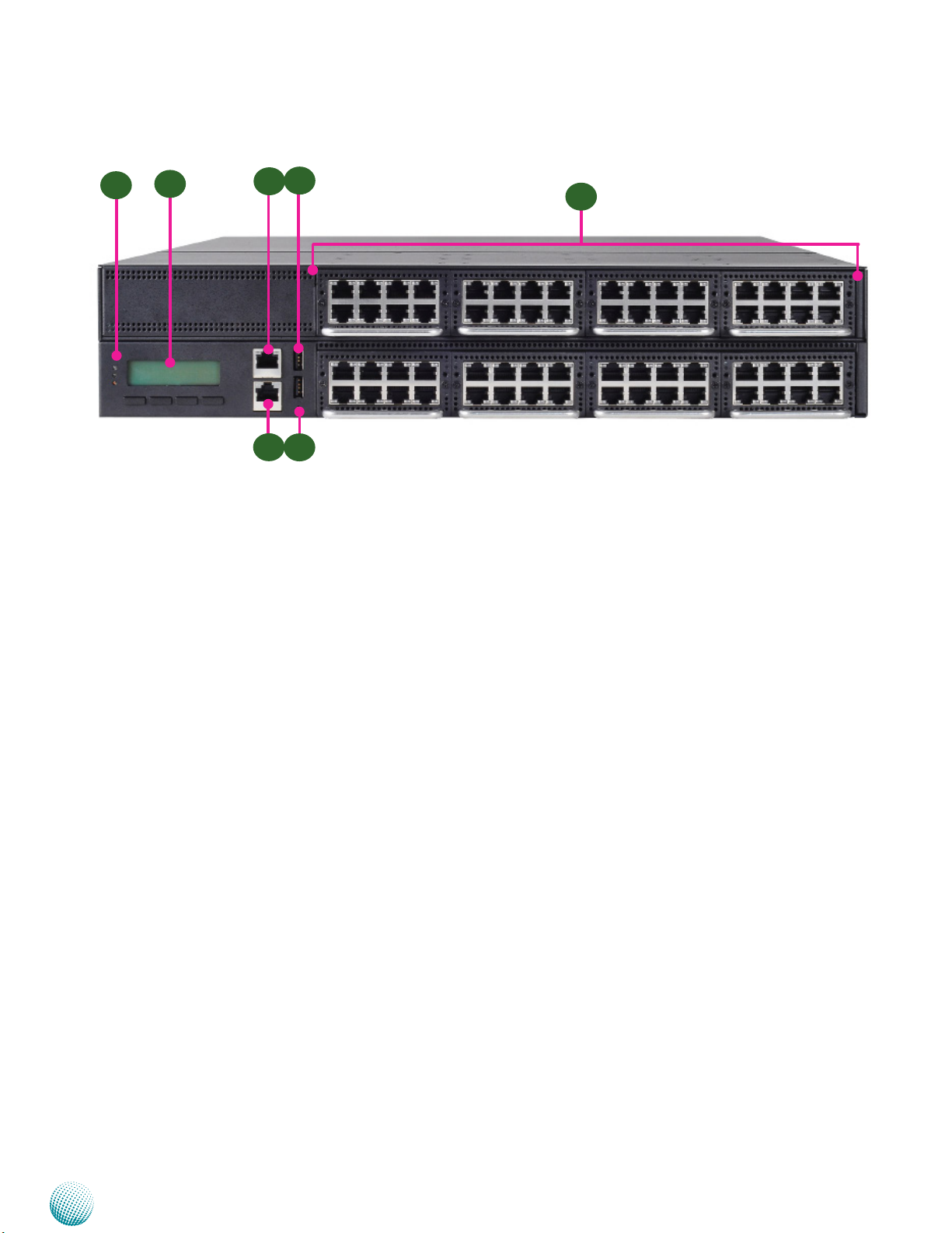
Front Panel Features
F1
F1 Power/Status/HDD LED
F2
F3
F4
Introduction
F6
F7
F5
Power: If the LED is on it indicates that the system is powered on. If it is off, it indicates that the system is powered off.
Status: This LED is programmable. You could program it to display the operating status with the behavior like:
If the LED is green, it indicates that the system’s operational state is normal. If it is red, it indicates that the system is
malfunctioning.
HDD: If the LED blinks, it indicates data access activities; otherwise, it remains off.
F2 System Panel: LCD System Panel
The LCD System Panel can be programmed to display operating status and configuration information. For more details
or sample programming code, please refer to the Drivers and user’s manual CD.
F3 Management Port
This FastEthernet port can be connected for configuration or troubleshooting purpose. A conformity with IPMI (Intelligent
Platform Management Interface) can be implemented through OPMA on this interface.
F4 Console Port
By using suitable rollover cable or RJ-45 to DB-9 Female (Cisco console cable), you can connect to a computer terminal
for diagnostic or configuration purpose. Terminal Configuration Parameters: 115200 baud, 8 data bits, no parity, 1 stop
bit , no flow control.
F5 Reset Switch
The reset switch can be used to reboot the system without turning off the power.
F6 Two USB 2.0 Ports
It connects to any USB devices, for example, a flash drive.
F7 Swappable Ethernet Modules (with LAN bypass model options)
LINK/ACT (Yellow)
• On/Flashing: The port is linking and active in data transmission.
• Off: The port is not linking.
SPEED (Green/Amber)
• Amber: The connection speed is 1000Mbps.
• Green: The connection speed is 100Mbps
• Off: .The connection speed is 10Mbps.
Network Application Platforms
3
Page 8

Chapter 1
Introduction
Using suitable RJ-45 cable, you can connect FW-8895 System to a computer, or to any other piece of equipment that has
an Ethernet connection; for example, a hub or a switch. Moreover, 2 or 4 pair (LAN1-LAN2, LAN3-LAN4, LAN5-LAN6, LAN7LAN8) on the Ethernet module can be configured as LAN Bypass when failure events occur (depending on the type of LAN
modules). This feature can be implemented with a watch dog timer to enable it automatically. Refer to your User’s Manual
CD for a sample implementation of this feature.
Note:
1. The availability of LAN Bypass varies depending on the model of Ethernet LAN module. For more information, visit
the Lanner product website at www.lannerinc.com/x86_Network_Appliances/Network_Modules
2. The number of LAN modules varies depending on the model.
FW-8895A FW-8895B FW-8895C FW-8895D
with Cavium CN1620 without Cavium CN1620 with Cavium CN1620 without Cavium
CN1620
8 LAN modules in the front panel 8 LAN modules in the front panel 4HDD and 4 LAN
modules in the front
panel
3. The management port is optional depending on the model.
4 HDD and 4 LAN
modules in the front
panel
Network Application Platforms
4
Page 9
Chapter 1
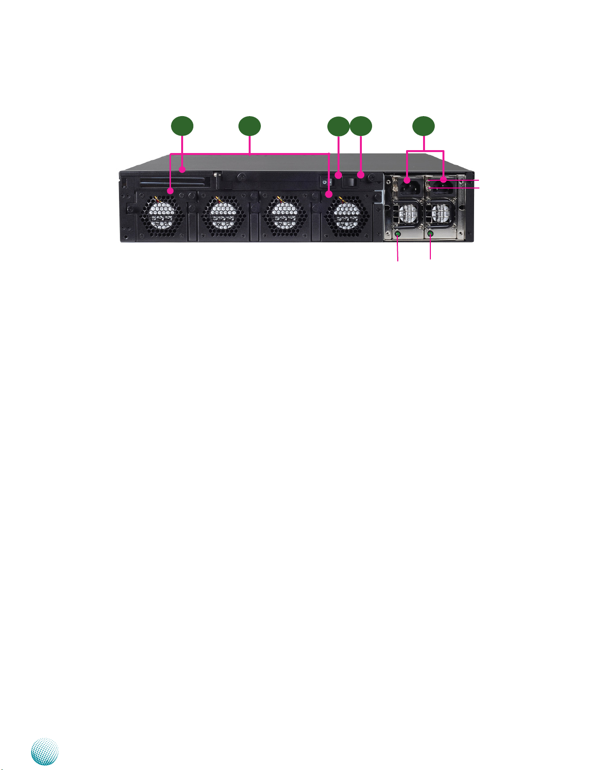
Rear Panel Features
Introduction
R1
R1 Low Profile Expansion Slot
R2 4 Moduler Fans (Corresponding connectors on the mainboard from left to right: FAN3, FAN2, FAN1, FAN4).
R3 Power-on Switch
It is a switch to turn on or off the power.
R4 Power Supply Alarm Switch
When the alarm sounds (it indicates a power supply failure), switch off this button to turn off the alarm. Replace the failed
power supply as soon as possible.
R5 Redundant Power Supply
The 600W redundant power supply is hot-swappable and can be withdrawn and replaced when the alarm sounds. The
LED of the failed power supply will be turned off. To replace the failed power supply unit, unscrew the screw and press
the latch to release the unit and pull it out.
R2 R5R4
R3
PSU latch
screw
PSU LED
Network Application Platforms
5
Page 10
Chapter 2
Introduction
Chapter 2:
Hardware Setup
Preparing the Hardware Installation
To access some components and perform certain service
procedures, you must perform the following procedures
first.
WARNING: To reduce the risk of personal injury,
electric shock, or damage to the equipment,
remove the power cord to remove power from the
server. The front panel Power On/Standby button
does not completely shut off system power.
Portions of the power supply and some internal
circuitry remain active until AC power is removed.
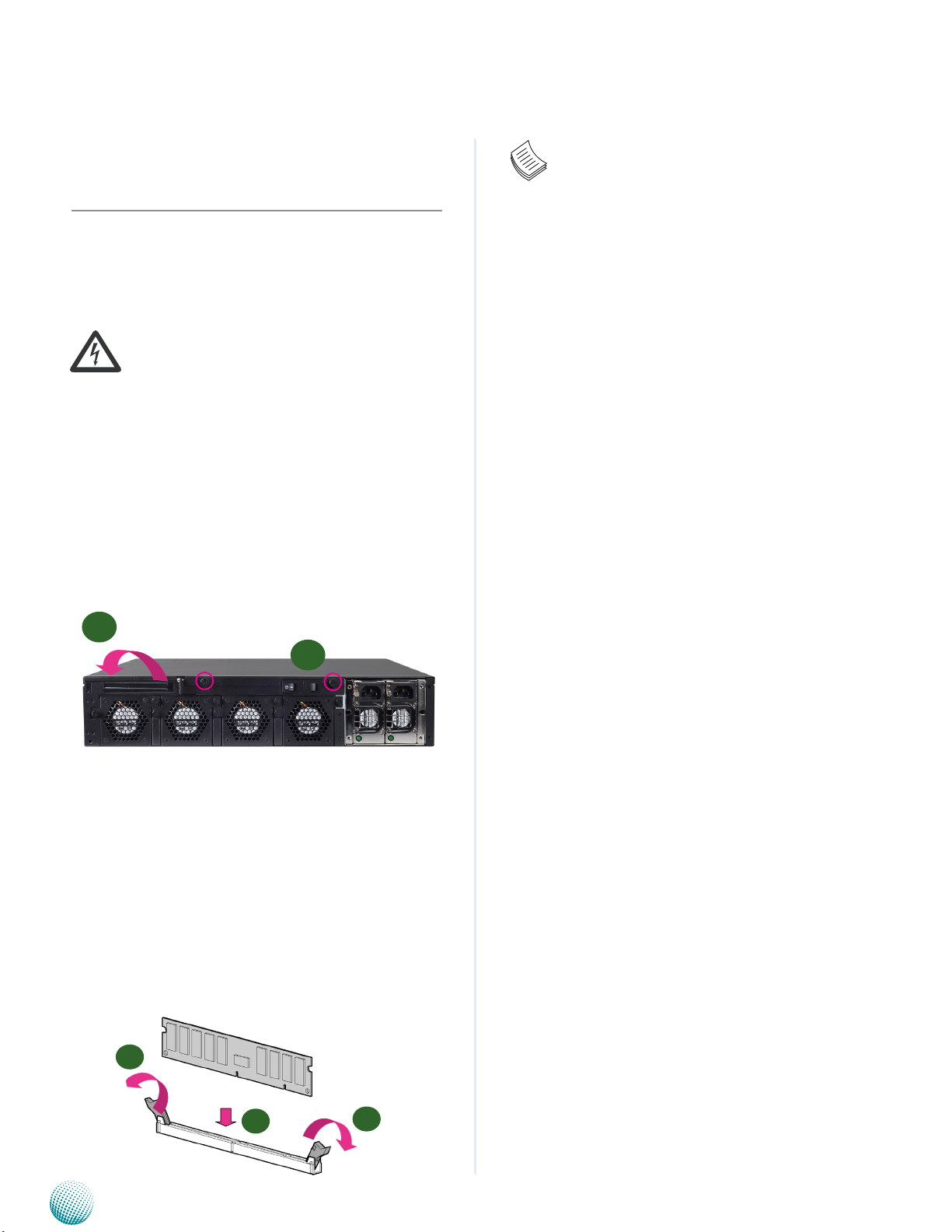
1. Unpower the FW-8895 and remove the power cord.
2. Unscrew the 2 thumbscrews from the top cover of the
FW-8895 System.
3. Slide the cover backwards and open the cover.
2
1
Note:
1. The motherboards can support up to 128 GB
memory capacity in maximum (registered ECC or
unbuffered ECC).
2. The system support dual CPU configuration. If
you have only one CPU, populate the DIMMs
close to the installed CPU socket
3. Since the system is capable of Quad Channel
configuration, some installation guidelines have
to be followed to enable Quad Channel mode:
To insert 4 DIMMs on the system, insert DIMMS
into the 4 slots with black latches nearest to the
designated CPU socket (CPU socket No1 or No2).
And use slots with white latches if more slots are
required.
4. To activate Dual Channel instead of Quad
Channel in the system, populate any 2 slots with
black latches nearest to the designated CPU
socket (CPU socket No1 or No2). And then use
slot with white latch that belongs to the same
channel as the populated slot with black latch for
any additional DIMMs.
5. Starting from the board edge (same for both CPU
socket No1 and No2), one pair of black and whitelatched slots is configured as one channel.
unscrew the thumbscrews on
the back and open the top
cover.
Installing the System Memory
The motherboard supports DDR3 memory to meet the
higher bandwidth requirements of the latest operating
system and Internet applications. It comes with QuadChannel DDR3 Dual Inline Memory Modules (DIMM)
sockets (a total of 16 DIMMs for 2 CPUs).
1. Open the DIMM slot latches.
2. Install the DIMM.
1
2
Network Application Platforms
1
6
Page 11
Chapter 2
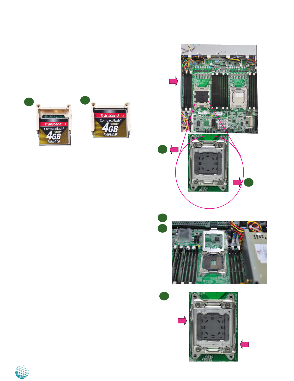
Installing the CompactFlash Card
FW-8895 provides one CompactFlash slot. Follow the
procedures bellow for installing a CompactFlash card.
1. Align CompactFlash card and the card slot with the
arrow pointing toward the connector.
Introduction
2. Push the card to insert into the connector.
1
2
.
Installing CPU and the Heat Sink
The FW-8895 sever system is powered by the MB-8895
sever board, which comes with two LGA2011 CPU
sockets.
Follow the procedures bellow for installing a CPU
1. Remove the CPU socket cap.
2. Press the load lever and release it from the retention
tab. There are two levers for each CPU socket. Follow
the sequence as instructed on the right to release
both of them.
3. Lift the load lever and then the plate.
Left side
notch on the socket
1
Open this side of
lever rst
2
and then open this
side of lever
3
4
4. Align the cut edge of the CPU and the notch on the
socket. The CPU should fit perfectly into the socket.
Note that the CPU fits in the socket in only one
direction.
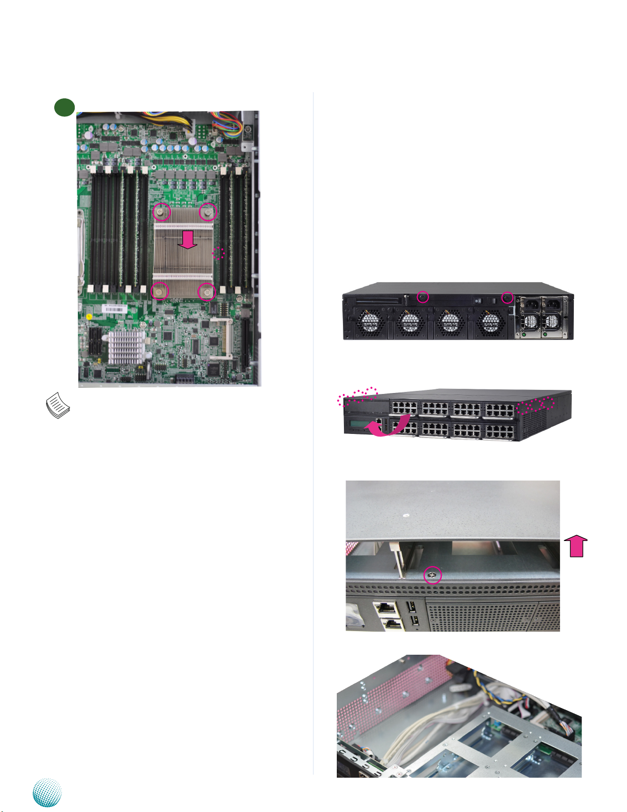
5. Close the plate and push the load lever to lock it back
to the retention tab.
6. Put the heat sink on the installed CPU, match the
screws with the screw holes on the board. Fasten two
screws which are opposite to each other at a time and
then the other two. It is easier this way to avoid the
5
force of spring.
7. Place the heat sink cover on top of the installed heat
and then close
this side of lever
sink and to fasten it with screws on the chassis.
Close this side of
lever rst
Network Application Platforms
7
Page 12
Chapter 2
Introduction
6
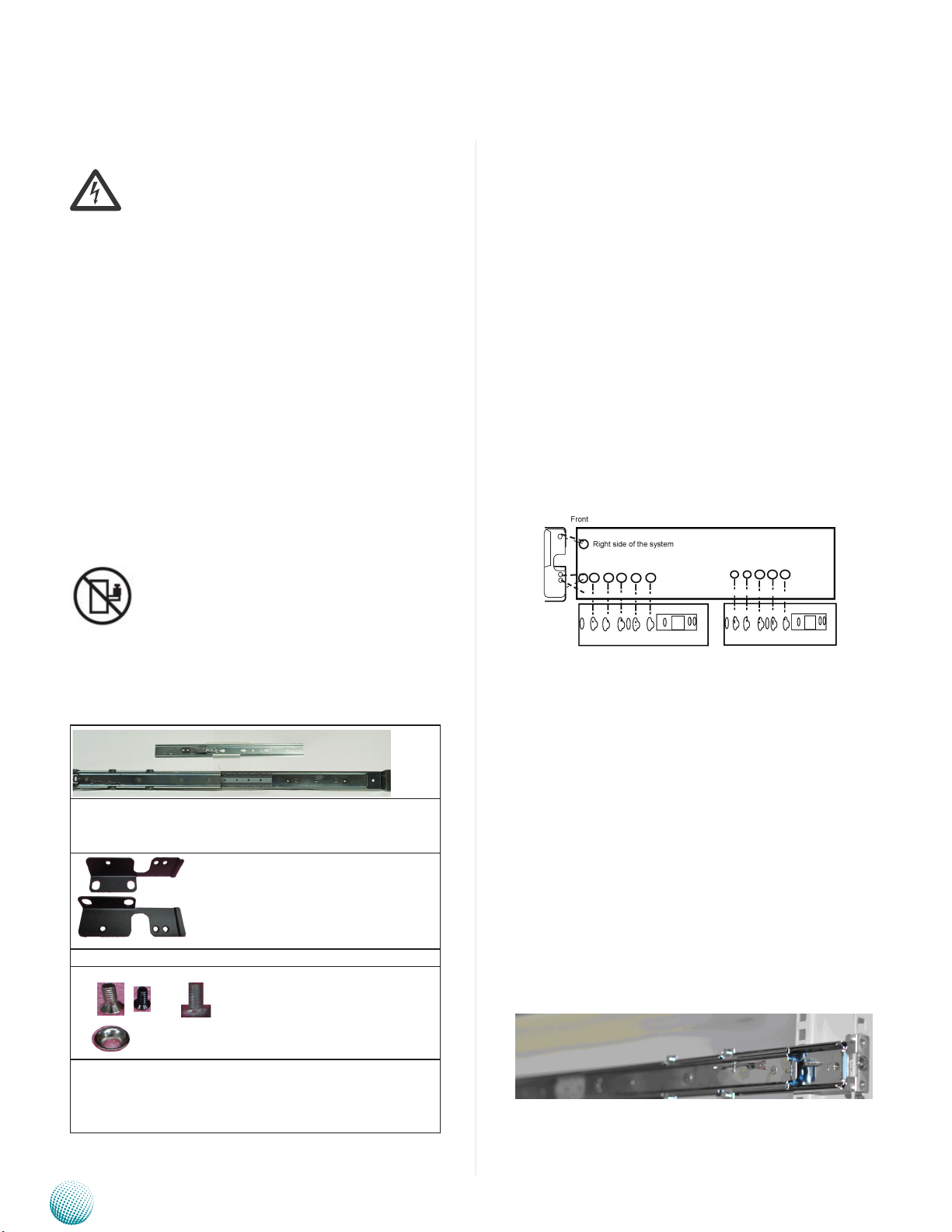
Installing the Hard Disk
For models FW-8895A and FW-8895B, the system support
two internal HDD installation. However, it requires that
the top compartment to be unmounted.
To unmount the top compartment, follow these steps:
1. Take off the back cover by unscrewing two
thumbscrews on the back. Disconnecting any
cables that connect to the connectors of the top
compartment.
2. To take out the top compartment, unscrew 3 screws
from both sides and one screw on the bottom of the
compartment.
3. Lift the compartment to unmount it from the system.
unscrew the thumbscrews on
the back and open the back
cover.
Note:
1. If you have only one CPU, install it on the left
side (CPU socket No.1with the front panel
facing you). Failure to do so will result in boot
failure .
2. To protect the CPU socket pins, retain the CPU
cap when the CPU is not installed.
Take out the rst expansion
module in the front slot and
unscrew the screw on the bottom of the compartment
Lift the front compartment to
unmount it from the system
Network Application Platforms
Hard disk mounting location
8
Page 13
Chapter 2
Introduction
Inner Rail Installation
Rack Mounting
Installation environment caution:
1. Elevated Operating Ambient - If installed in a closed
or multi-unit rack assembly, the operating ambient
temperature of the rack environment may be greater
than room ambient. Therefore, consideration should be
given to installing the equipment in an environment
compatible with the maximum ambient temperature
(Tma) specified by the manufacturer.
2. Reduced Air Flow - Installation of the equipment in
a rack should be such that the amount of air flow
required for safe operation of the equipment is not
compromised. Mechanical Loading - Mounting of the
equipment in the rack should be such that a hazardous
condition is not created due to uneven mechanical
loading.
3. Circuit Overloading - Consideration should be given to
the connection of the equipment to the supply circuit
and the effect that overloading of the circuits might
have on over-current protection and supply wiring.
Appropriate consideration of equipment nameplate
ratings should be used when addressing this concern.
4. Reliable Earthing - Reliable earthing of rack-mounted
equipment should be maintained. Particular attention
should be given to supply connections other than
direct connections to the branch circuit (e.g. use of
power strips).”
CAUTION :
Use the following procedures to attach the inner rails to
the chassis.
1. Position the inner rail alongside the side of the
system’s chassis with the finger tab facing outward as
shown in the following diagram.
2. Align the screw holes of the rail and the mounting
holes of the chassis and then attach the inner rail to
the system with crosshead threaded screws.
3. Repeat the above steps for the other rails on the same
side (two inner rails need to be installed on each
side).
4. Attach the front ear bracket (short) to the system.
5. Likewise, attach the inner rails and front ear bracket
to the other side of system’s chassis.
Slide/rail mounted equipment is not to be used as a
shelf or a work space.
Package Contents
3 pairs of sliding rails:
-The inner rails(x4)
-The outer rails (x2)
Front ear bracket (short ear bracket for rail mount)
1. 2. 3.
Screw pack: 1. countersink screws and conical washers
for outer rail mout
2. ear-bracket screws.
3. crosshead threaded screws for inner rail mount
Mounting the outer rails to the rack
Use the following procedures to mount the outer rails to
the rack.
1. Install the outer rail by attacking the rail bracket
to the posts of the rackby using two countersink
screws and conical washers(You may also use the
original manufacture’s rack bracket screws.) Do not
completely tighten the screws; leave them loose so
that the middle rail can slide for adjustment.
2. Extend and adjust the rear bracket to meet the
appropriate depth of the rack and install it to the rack
post firmly with rack bracket screws.
3. Repeat step 1 and 2 above to install the other rail to
the rack.
Network Application Platforms
9
Page 14
Chapter 2
Introduction
Installing the system to the rack
1. Extend the rails until they lock into place.
2. Holding the system with its front facing you, align the
unit with the extended rails and carefully insert the
system by sliding the inner rail into the outer rail. Push
the chassis all the way toward the back until the front
ear brackets contact the rack. Remember to release
the extension safety lock along the way.
3. You may also fix the front ear brackets (short) to the
rack if the system doesn’t require frequent pulling out
of the rack.
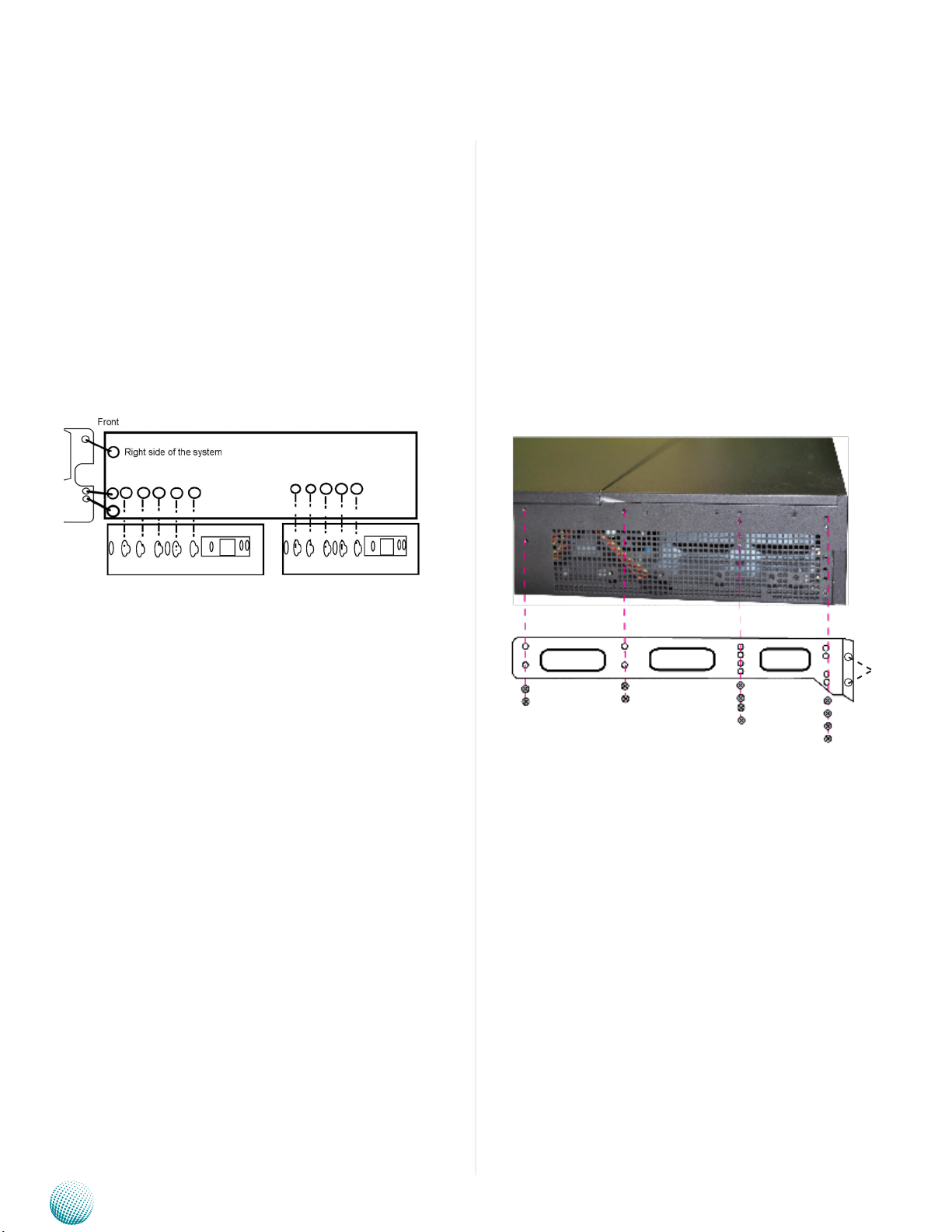
Installing the Front Rack-Mount Ear Bracket
Attach the front rack-mount (long) brackets. Locate the
threaded holes along sides of the chassis and use the
package of black screws that shipped with the chassis.
1. Align the front rack-mount bracket to one side of the
chassis.
2. Insert and tighten the screws on one side.
3. Repeat the above steps for the other side of the
chassis.
4. Installing the system to the rack
Front
Left side of the system
Rackmount
holes
Network Application Platforms
10
Page 15

Chapter 3
Chapter 3:
Motherboard Information
Block Diagram
The block diagram depicts the relationships among the
interfaces or modules on the motherboard. Please refer
to the following figure for your motherboard’s layout
design.
Motherboard Information
Network Application Platforms
11
Page 16

Chapter 3
Motherboard Layout
The motherboard layout shows the connectors and
jumpers on the board. Refer to the following picture
as a reference of the pin assignments and the internal
connectors.
Motherboard Information
AT Mode Power Button Connector (CONN1)
CPU Socket NO. 1
DIMM Socket
Power Switch (SW1)
Front Panel LCD Connector (J23)
ATX5
J22
VGA1
OPMA Connector
USB1
Fan 4 Fan 2 Fan 3
Fan 1
J27
CPU Socket
No.1
ATX1
ATX3
DIMM Socket
CPU Socket NO. 2
Management Port, MGT1
CF Card Connector, CF1
Reset Switch (SW2)
COMA1
Network Application Platforms
COMB1
OPEN1
Management Port, MGT2
SATA4
SATA3
OPEN2
CMOS (J24)
Front LCM in USB (LCM_1)
USB2
SATA2
SATA 1
12
Page 17

Chapter 3
Motherboard Information
Jumper Settings
LCM_1: USB-type front LCD Message Display Module
(LCM). It supports both text and graphic type of LCM. The
board also facilitates Parallel -type LCM connector, refer to
jumper J23.
9 1
10 2
Pin No. Function Pin No. Function
1 P5V_SB 2 P5V
3 USB_PCH_P5N 4
5 USB_PCH_P5P 6 HDD_LED_N
7 GND 8 GND
9 NTXD2 10 NRXD2
LCM_2: USB-type front LCD Message Display Module
(LCM). This connector is reserved for customization
purpose.
2 10
1 9
Pin No. Function Pin No. Function
1 P5V_SB 2 USB_PCH_P4N
3 USB_PCH_P4P 4 GND
5 PWR_LED- 6 FAULT_N
7 HDD_LED_N 8 PWRON_N
9 P3V3_AUX 10 PCH_PLTRST_LCM_N
MGT1: RJ 45 management port connector
1
3
5
7
9
11
Pin No. Function Pin No. Function
1 MGT2_MDIP_0 2 MGT2_MDIN_0
3 MGT2_MDIP_1 4 MGT2_MDIN_1
5 MGT2_MDIP_2 6 MGT2_MDIN_2
7 MGT2_MDIP_3 8 MGT2_MDIN_3
9 MGT_LAN2_100# 10 MGT_LAN2_ACT#
11 MGT_LAN2_1G# 12 P3V3_AUX
Note: Unlike the other management port
connector (MGT2), it doesn’t share an output port
(the Management port on the front panel) with
the IPMI signal Hence, no switch is required to
switch between these two signals.
2
4
6
8
10
12
Pin No. Function Pin No. Function
1 MGT2_MDIP_0 2 MGT_MDIN_0
3 MGT2_MDIP_1 4 MGT_MDIN_1
5 MGT2_MDIP_2 6 MGT_MDIN_2
7 MGT2_MDIP_3 8 MGT_MDIN_3
9 MGT_LAN_100# 10 MGT_LAN_ACT#
11 MGT_LAN_1G# 12 P3V3_AUX
Note: This MGT2 signal will not pass through
when the IPMI card is present (board reference NO.
OPMA1); The management port and IPMI share
the same output port (the Management port on
the front panel). Use the jumper OPEN2 to switch
between these two signals.
ATX5: 24-Pin ATX Power Connector
23
21
19
1
Pin No. Function Pin No. Function
1 +3.3V 2 +3.3V
3 +3.3V 4 -12V
5 Ground 6 Ground
7 +5V 8 PSON-
9 Ground 10 Ground
11 +5V 12 Ground
13 Ground 14 Ground
15 Power Good 16 NC
17 Stand-By 5V 18 +5V
19 +12V 20 +5V
21 +12V 22 +5V
23 3.3V 24 GND
24
23
20
2
ATX1, ATX3: 8-Pin ATX Power Connector
2
4
6
8
1
Pin No. Function Pin No. Function
1 GND 2 12V
3
3 GND 4 12V
5
5 GND 6 12V
7
7 GND 8 12V
MGT2: RJ 45 management port connector
12
10
8
6
4
2
Network Application Platforms
11
9
7
5
3
1
SATA1: SATA Revision III Drive Connector
SATA2~SATA4: SATA Revision II Drive Connector
It is for connecting a 3.5’’ SATA harddisk to be served
as your system’s storage. The system can support up to
4 3.5" disks in maximum. The system’s BIOS supports
13
Page 18

Chapter 3
Motherboard Information
3 modes of SATA configuration, i.e., IDE, RAID, and AHCI.
The chipset provides hardware support for Advanced
Host Controller Interface (AHCI) which is a programming
interface for SATA host controllers. AHCI provides advanced
performance and usability enhancements with SATA such
as Hot-Plug, no master/savle designation for SATA devices
and native command queuing (NCQ).
Pin No. Function
7
6
5
1
1 GND
2 TX_P
3 TX_M
4 GND
5 RX_M
6 RX_P
7 GND
Note:
1. To configure your Hard disk using the
integrated RAID feature, the Intel®Rapid
Storage Technology Utility has to be installed
on your Operating System.
2. You will need to select the RAID mode in the
BIOS for your SATA drives first. There is also a
Intel® RSTe OpROM utility for creating RAID
volume; to enter the RSTe OpROM, press Ctrl-I
during POST.
3. For operating systems other than Microsoft®
Windows Vista and Windows® 7, it is
required to pre-install the Intel Rapid Storage
Technology driver during the F6 installation of
Windows setup (“press F6 if you need to install
a third party SCSI or RAID driver....”).
Visit the Intel support page at http://www.intel.
com/p/en_US/support/highlights/chpsts/imsm
for more information and download links.
4. The Intel controller hubs are also supported
by Linux. Beginning with Linux kernel
version 2.6.27, the mdadm utility 3.0
supports RAID 0, RAID 1, RAID 5, and RAID
10. To use the RAID features in dmraid and
mdadm, you will need to set up the RAID
volume using the Intel® Matrix Storage
Manager option ROM (click CTRL + I when
prompted during boot to enter the option
ROM user interface).
FAN1~4: 5-Pin FAN Connector. The 4-pin connector
is for connecting the CPU and system fans. These fans
have smart features that which can are automatically set
to operate at certain speed according to the deteced CPU
or system temperatures. For more information, see Smart
Fan Mode Configuration on Chapter 4 BIOS Settings.
5
4
3
2
1
Network Application Platforms
Pin No. Description
1 Ground
2 12V
3 RPM Sense
4 RPM Sense
5 PWM Status
CONN1: Power-on Switch
Pin No. Description
1 Ground
2 1
2 FP_SWIN_R
SW1: on-board power switch for debug.
2 4
1 3
Pin No. Description
1 Ground
2 Ground
3 FP_SWIN_R
4 FP_SWIN_R
SW2: An onboard reset button for debug purpose.I
4 3
2 1
Pin No. Description
1 Ground
2 Ground
3 FP_RST_SEL
4 FP_RST_SEL
USB1: USB Connector. It is for connecting the USB
module cable. It complies with USB2.0 and support up
to 480 Mbps connection speed.
10
9
8
7
6
5
4
3
2
1
Pin No. Description Pin No. Description
1 USB_VCC 2 USB_VCC
3 USBD0- 4 USBD15 USBD0+ 6 USBD1+
7 Ground 8 Ground
9 USB Port#1Ground 10 USB Port#2 Ground
USB2: USB Connector
9 7 5 3 1
10 8 6 4 2
Pin No. Description Pin No. Description
1 USB_VCC 2 USB_VCC
3 USBD2- 4 USBD35 USBD2+ 6 USBD3+
7 Ground 8 Ground
9 USB
Port#3Ground
10 USB Port#4
Ground
14
Page 19

Chapter 3
Motherboard Information
VGA1: VGA Interface. with a 2x6 (2.54”) pin header.
It is for connecting the VGA interface cable. Note the
IPMI card (connector Reference NO. OPMA1) has to be
present for this connector to work, i.e., the IPMI card
provides VGA interface/signal.
12
10
8
6
4
2
Pin No. Function Pin No Function
1 R 2 Ground
3 G 4 Ground
5 B 6 Ground
7 H-SYNC 8 Ground
9 V-SYNC 10 Ground
11 Detect-display
Data
11
9
7
5
3
1
12 Deteck-display
CLOCK
Note: A 2x6 pin (2.0”) header (J1) on the OPMA card
is also provided as an VGA interface connector.
CF1: CF Card Connector
Pin No. Description Pin No. Description
1 GND 26 CD12 DATA3 27 DATA11
3 DATA4 28 DATA12
4 DATA5 29 DATA13
5 DATA6 30 DATA14
6 DATA7 31 DATA15
7 CE1# 32 CE2#
8 A10 33 VS1#
9 OE# 34 IOR#
10 A9 35 IOW#
11 A8 36 WE#
12 A7 37 READY#
13 CFVCC3 38 CFVCC3
14 A6 39 CSEL
15 A5 40 VS2#
16 A4 41 RESET
17 A3 42 WAIT#
18 A2 43 INPACK#
19 A1 44 REG#
20 A0 45 DASP#
21 DATA0 46 DIAG#
22 DATA1 47 DATA8
23 DATA2 48 DATA9
24 WP 49 DATA10
25 CD2- 50 GND
J23: Parallel -type front LCM connector. It supports
both text and graphic type of LCM. The board also
facilitates USB -type LCM connector, refer to jumper
LCM_1.
2
1
4
3
6
5
24
23
Network Application Platforms
PIN DESCRIPTION PIN DESCRIPTION
1 VCC 2 IOGND
3 LSTIN- 4 VEE
5 LAFD- 6 LINIT7 LPD1 8 LPD0
9 LPD3 10 LPD2
11 LPD5 12 LPD4
13 LPD7 14 LPD6
15 LCD 16 VCC
17 K1 18 K2
19 K3 20 K4
21 RESET 22 VCC3
23 GPIO 24 VCC3
COMA1: COM PORT Connector
9
10
7
8
5
6
3
4
1
2
Pin No. Description Pin No. Description
1 DCD1 2 DSR1
3 RXD1 4 RTS1
5 TXD1 6 CTS1
7 DTR1 8 RI1
GND 10 FP_RESET_N
COMB1: COM PORT
9 7 5 3 1
10 8 6 4 2
Pin No. Description Pin No. Description
1 DCD2- 2 DSR23 RXD2 4 RTS25 TXD2 6 CTS27 DTR2- 8 RI29 GND 10
DIMM Sockets:
Since the system is capable of Quad Channel
configuration, some installation guidelines have to be
followed to enable Quad Channel mode. To insert 4
DIMMs on the system, insert DIMMS into the 4 slots with
black latches nearest to the designated CPU socket (CPU
socket No1 or No2). And then use slots with white latches
if more slots are required.
Note:
1. To activate Dual Channel instead of Quad
Channel in the system, populate any 2 slots
with black latches nearest to the designated
CPU socket (CPU socket No1 or No2). And then
use slot with white latch that belongs to the
same channel as the populated slot with black
latch for any additional DIMMs.
2. Starting from the board edge (same for both
CPU socket No1 and No2), one pair of black
and white-latched slots is configured as one
channel.
15
Page 20

Chapter 3
Motherboard Information
CPU Socket NO.1 and CPU Socket NO. 2: When
using only one CPU, install the CPU on the socket NO.1 or
the system will not function.
OPMA1: OPMA Connector. The OPMA connector
is for connecting the OPMA card. When the OPMA card
is connected, the management port will comply with
the Intelligent Platform Management Interface (IPMI)
standard.
OPEN2: A switch to switch the output signal
between MGT2 and OPMA1 since they share
the same access port (the management port
on the front panel). To let the MGT2 signal pass
through instead of the OPMA signal, take out this
jumper. In this way, you could have both VGA and
Management connections.
Pin No. Description
1
2
Short1-2 IPMI Pass-through
(default)
Open 1-2 MGT2 Pass-through
Note: To have both VGA and Management (nonIPMI compliant) connections, take out the jumper
block.
J27: A reset switch to switch between hardware and
software reset function for the front panel reset button.
A hardware reset function will reset the whole system
while a software reset function will reset the designated
software to its default value.
3 2 1
Pin No. Description
1-2 Hardware Reset
2-3 Software Reset
OPEN1: Case open detection jumper. Use this to
detect case open event.
1
2
Pin No. Description
1 GROUND
2 CSOPEN_N
J24: Clear CMOS Jumper. Use this jumper to reset the
BIOS setting to its factory default.
1 2 3
Pin No. Description
1-2 Normal (default)
2-3 Clear CMOS
Note: A 2x6 pin (2.0”) header (J1) on the OPMA
card is provided as an VGA interface connector.
Network Application Platforms
16
Page 21

Chapter 4
Chapter 4:
BIOS Settings
Updating the BIOS
The Basic Input/Output System (BIOS) can be updated
using the designated Flash Utility. To obtain the utility,
please contact us either through the sales rep or technical
support.
Bios Settings
Network Application Platforms
17
Page 22

Chapter 4
Accessing the BIOS menu
When you are installing a motherboard or when the
system prompts “Run Setup” during start-up, you will use
the BIOS Setup program to configure the system, . This
section explains how to configure your system using this
program.
Even if you are not prompted to enter the BIOS Setup
program when you are installing a motherboard, you can
still change the configuration of your computer later on
with this program. For example, you may want to enable
the security password feature or change the power
management settings. This requires you to reconfigure
your system by using the BIOS Setup program so that the
computer can recognize these changes and record them
in the CMOS RAM .
When you start up the computer, the system provides you
with the opportunity to run this program. Press <Delete>
during the Power-On-Self-Test (POST) to enter the Setup
utility (There are a few cases that other keys may be
used, such as <F1>, <F2>, and so forth.); otherwise, POST
continues with its test routines.
If you wish to enter Setup after POST, restart the system
by pressing <Ctrl+Alt+Delete>, or by pressing the reset
button on the system chassis. You can also restart by
turning the system off and then back on. Do this last
option only if the first two failed.
The Setup program is designed to make it as easy to use as
possible. Being a menu-driven program, it lets you scroll
through the various sub-menus and make your selections
from the available options using the navigation keys.
Bios Settings
Keys Description
-><- Left/Right The Left and Right <Arrow> keys
->
->
Up/Down The Up and Down <Arrow> keys
+- Plus/Minuss The Plus and Minus <Arrow> keys
Tab The <Tab> key allows you to select
allow you to select an setup screen.
For example: Main screen, Advanced
screen, Boot screen, and so on.
allow you to select an setup item or
sub-screen.
allow you to change the field value
of a particular setup item. For
example: Date and Time.
setup fields.
Note: This manual describes the standard look of
the setup screen. There may be some instances in which
the motherboard features can vary from one to another
due to customization. This means that some of the options
described in this manual mays not match that of your
motherboard’s AMIBIOS.
Navigating the BIOS menu
The BIOS setup utility uses a key-based navigation system
called hot keys. Most of the BIOS setup utility hot keys can
be used at any time during the setup navigation process.
These keys include <F1>, <F10>, <Enter>, <ESC>, <Arrow>
keys, and so on.
Network Application Platforms
Note: The <F8> key on your keyboard is the Fail-Safe key.
It is not displayed on the key legend by default. To set the
Fail-Safe settings of the BIOS, press the <F8> key on your
keyboard. The Fail-Safe settings allow the motherboard
to boot up with the least amount of options set. This can
lessen the probability of conflicting settings.
18
Page 23

Chapter 4
The Main Menu
The main BIOS setup menu is the first screen that you can
navigate. Each main BIOS setup menu option is described
in this chapter.
The Main BIOS setup menu screen has two main frames. The
left frame displays all the options that can be configured.
“Grayed-out” options are configured parameters and
cannot be modified. On the other hand, Options in blue
can be modified.
The right frame displays the key legend. Above the key
legend is an area reserved for a text message. When an
option is selected in the left frame, it is highlighted in
white. Often a text message will accompany it.
Bios Settings
System Language
Use this item to choose the BIOS language.
System Time/System Date
Use this option to change the system time and date.
Highlight System Time or System Date using the <Arrow>
keys. Enter new values through the keyboard. Press the
<Tab> key or the <Arrow> keys to move between fields.
The date must be entered in MM/DD/YY format. The time
is entered in HH:MM:SS format.
Network Application Platforms
19
Page 24

Chapter 4
Advanced Settings
Select the Advanced tab from the setup screen to enter
the Advanced BIOS Setup screen. You can select any of
the items in the left frame of the screen, such as SuperIO
Configuration, to go to the sub menu for that item. You
can display an Advanced BIOS
Setup option by highlighting it using the <Arrow> keys.
All Advanced BIOS Setup options are described in this
section. The Advanced BIOS Setup screen is shown at
the right. The sub menus are described on the following
pages.
Bios Settings
Restore AC Power Loss
This option lets you set the state of the system when it has
just recovered from a power outage.
Option Description
Power Off When setting to Power Off, the system goes into
“off state” after an AC power interruption.
Power On When setting to Power on, the system turns on
automatically after a power interruption
Last State When setting to Last State, the system goes
into whatever the state was before the power
interruption.
Intel VT-d
Select to enable or disable the Intel Virtualization
Technology for Directed I/O” (VT-d). The Memory and
I/O virtualization are supported by the chipset as part
of Intel Virtualization Techonology for hardware-assisted
virtualization.
Network Application Platforms
20
Page 25

Chapter 4
LAN PXE Boot
The Preboot eXecution Environment (PXE) allows you to
boot computers using a network interface independently
of data storage devices (like hard disks) or installed
operating systems. Enable or disable this function with
this option here.
CPU Information
You can use this screen to view the basic information and
capabilities of your CPU. For instance, the L1 to L3 level
cache sizes and the clock rate are displayed here.
Bios Settings
CPU Configuration Settings
You can use this menu to enable/disable certain functions
of your CPU. Use the up and down <Arrow> keys to select
an item. Use the <Plus> and <Minus> keys to change the
value of the selected option. A description of the selected
item appears on the right side of the screen. The settings
are described below.
Item Selection
Intel HyperThreading
Active Processor Core
Limit CPUID
Maximum
Execute Disable Bit
The Intel Hyper-Threading Technology
allows a hyper-threading processor to
appear as two logical processors to the
operating system, allowing the operating system to schedule two threads or
processes simultaneously.
Select to enable or disable this feature.
Select the number of processor cores to
be active in each processor package.
Allows legacy operating systems to boot
even without support CPUs with extended CPUID functions.
Select to enable or disable this function
Select to enable or disable the No-Execution Page Protection Technology.
Network Application Platforms
21
Page 26

Chapter 4
Item Selection
Hardware
Prefetcher
Adjacent
Cache Line P
DCU Streamer Prefetch
DCU IP
Prefetcher
Intel Virtualization
The processor has a hardware prefetcher
that automatically prefetches data and instructions from the memory into the Level
2 cache that are likely to be required in
the near future. This reduces the latency
associated with memory reads.
When enabled, the processor’s hardware
prefetcher will be enabled and allowed to
automatically prefetch data and code for
the processor.
When disabled, the processor’s hardware
prefetcher will be disabled.
Select to enable or disable prefetching of
adjacent line
Enable prefetch of next L1 Data Line
based on multiple loads in the same
cache line.
Enable prefetch of next L1 line based on
sequential load history.
The Intel VT is a hardware-assisted virtualization. This processor supports Intel Virtualization. Enable or disable this feature.
Bios Settings
SATA Mode Selection
The system supports advanced SATA features such as
software RAID.
Item Selection
IDE Mode Set to IDE mode when your want to use the
Serial-ATA hard disk drives as Parallel ATA physical
storage devices.
AHCI Mode Set to AHCI mode when you want the SATA
hard disk drives to use the AHCI (Advanced
Host Controller Interface). The AHCI allows the
onboard storage driver to enable advanced SATA
features that increases storage performance or
workloads where multiple simultaneous read/
write requests are outstanding, most often
occurring in server-type applications (native
command queuing). It also facilitates hot
swapping.
RAID Set to the RAID mode when you want to create
a RAID configuration from the SATA Hard disk
drives. Thie chipset supports software RAID by
using the Intel® Matrix Storage Manager
software. For more information, visit
http://www.intel.com/design/chipsets/
matrixstorage_sb.htm#benefit
Network Application Platforms
22
Page 27

Chapter 4
Aggressive Link Power
Aggressive Link Power Management (ALPM) is a powersaving technique that helps the disk save power by setting
a SATA link to the disk to a low-power setting during idle
time. Power savings come at the expense of disk latency. As
such, you should only use ALPM if you expect the system
to experience long periods of idle I/O time. ALPM is only
available on SATA controllers that use the Advanced Host
Controller Interface (AHCI).
Serial ATA Port 0/1/2/3/4/5
Use this menu to configure specific SATA Port for all ports
on the system.
Bios Settings
Option Description
Hot Plug The AHCI of SATA provides hot plug capability
to allow drives to be added or removed with the
PC running.
External
SATA
Staggered Spin-up
Spin-up can be employed to prevent the excessive powerconsumption of spin-up from resulting in a power shortage
in computers with multiple hard drives. Staggered spin-up
typically starts one drive at a time, either waiting for the
drive to signal it is ready or allowing a predefined period
of time to pass before starting the next drive. Select to
enable or disable this feature.
Called external SATA or eSATA, you can now
utilize shielded cable lengths up to 2 meters
outside the PC to transform SATA to be an
external storage. enable or disable this feature.
Network Application Platforms
23
Page 28

Chapter 4
USB Configuration Setting
You can use this screen to select options for the USB
Configuration. Use the up and down <Arrow> keys to
select an item. Use the <Plus> and <Minus> keys to
change the value of the selected option. The settings are
described on the following pages.
Legacy USB Support
This option enable or disable the support for USB devices
on legacy operating systems (OS), e.g., Windows ME/98/
NT, and MS-DOS. Normally if this option is not enabled,
any attached USB mouse or USB keyboard will not become
available until a USB compatible operating system is fully
booted with all USB drivers loaded. When this option is
enabled, any attached USB mouse or USB keyboard can
be used on the system even when there is no USB drivers
loaded on it.
Bios Settings
Option Description
Auto Allow the system to detect the presence of USB
devices at startup. If detected, the USB controller
legacy mode is enabled If it is not detected, the
USB control er legacy mode is disabled.
Enabled Enable the support for USB devices on legacy
operating system
Disabled Disable this function.
EHCI Hand-Off
It allows you to enable support for operating systems which do
not have the Enhanced Host Controller Interface hand-off (EHCI
hand-off ) feature for USB devices.
Option Description
Enabled Enable this feature
Disabled Disable this feature
Network Application Platforms
24
Page 29

Chapter 4
Port 60/64 Emulation
This BIOS feature allows you to enable emulation of I/O
ports 64h and 60h so that there is full PS/2 legacy support
for USB keyboards and mice. It is also useful in providing
USB keyboard and mouse support in Windows NT which
does not natively support USB.
Option Description
Enable The BIOS will emulate I/O
ports 64h and 60h for the
USB keyboard and mouse.
This enables PS/2 functionality like keyboard lock,
password setting and code
selection.
Disable The BIOS will not emulate
I/O ports 64h and 60h for
the USB keyboard and
mouse. They will not have
PS/2 functionality.
Bios Settings
USB Hardware Delays a
The menu sets delay time for USB operations.
Item Description
USB transfer
time-out
Device reset
time-out
Device
power-up
delay
set transfers to an endpoint to complete
within a specic time.
•Ifsettozero,transferswillnottimeout
because the host controller will not cancel
the transfer. In this case, the transfer waits
indenitely until it is manually canceled or
the transfer completes normally.
•Ifsettoanonzerovalue(time-outinterval), the host controller starts a timer when
it receives the transfer request. When the
timer exceeds the set time-out interval, the
request is canceled.
This option sets the reset timing for the
USB Mass Storage to be initialized.
When set to 10 Sec, the BIOS will wait for
up to 30 seconds for the USB ash drive to
initialize.
This option sets the power-up timing for
the USB Mass Storage to be initialized.
Network Application Platforms
25
Page 30

Chapter 4
PC Health Status
This menu shows the hardware monitor configuration
settings. Select an item then press <Enter> to display the
configuration options.
CPU0/CPU1/System Temp1/System Temp2
Temperature
The onboard hardware monitor automatically detects and
displays the CPU and motherboard temperatures.
FAN1B/FAN2B/FAN3B/FAN4B Speed
The onboard hardware monitor automatically detects
and displays the CPU , chassis and system fan speeds in
rotations per minute (RPM). If the fan is not connected to
the motherboard, it displays N/A.
Bios Settings
CPU Voltage, 3V voltage, 5V voltage voltage
The onboard hardware monitor automatically detects the
voltage output through the onboard voltage regulators.
Smart Fan Mode Configuration
It allows you to configure the smart fan feature. You can
manually turn on the CPU fan or enable the smart fan
feature. And the CPU fan can be turned on automatically
and operate at a slower or faster speed according to
a preset temperature and duty cycle values. Refer to
Motherboard Layout on Chapter 3 Block Diagram for
CPU and system fan connectors. Note that all fans are
configured the same with a uniform configuration.
Item Selection
Manual
Mode
Smart Fan
Mode
Manually set the fan speed
The preset the target CPU and system temperature at which the system fan will start
running according to a preset duty cycle %.
30(0C)......13.7% duty cycle
50(0C)......49% duty cycle
60(0C)......60.8% duty cycle
72(0C)......78.4% duty cycle
80(0C)......100% duty cycle
Network Application Platforms
26
Page 31

Chapter 4
SuperIO Configuration
In this screen, you will be able to modify the IRQ address
of the serial and parallel ports which are provided by the
Winbond SuperIO chip.
Serial Port 0/1 Configuration
This option specifies the base I/O port address and
Interrupt Request address of serial port 0 and 1.
item Selection
Enabled/
Disabled
Change
Settings
Set this value to prevent the serial port from
accessing any system resources. When this
option is set to Disabled, the serial port physically
becomes unavailable.
Selects the serial port base address and IRQ for
the interrupt address.
Bios Settings
Parallel Port Configuration
This option specifies the I/O address used by the parallel
port.
Item Selection
Parallel Port Enable or disable this parallel port
Device
Settings
Device Mode Selects the modes from the following possibilities:
Selects the serial port base address
STD Printer, Standard Parallel Port (SPP), Enhanced
Parallel Port (EPP) and Extended Capabilities Port
(ECP). Currently, new products have support of a
mixture of these protocols. Consult your device’s
specification for exact protocols supported by
your product.
SPP: denotes normal or standard mode.
EPP: used specifically for non-printer devices that
would attach to the parallel port, particularly
storage devices that needed the highest possible
transfer rate.
ECP: used specifically to provide improved speed
and functionality for printers
Network Application Platforms
27
Page 32

Chapter 4
Console Redirection
Use this menu to set the settings for BIOS remote access
feature.
Item Selection
Console Redirection Enable or disable BIOS
through remote access
Console Redirection Settings
COM0/COM1 Console Redirection Settings
Item Selection
Terminal Type Sets the connection termi-
Bits per second, Data bits,
Parity, Stop Bits, Flow
Control
Enter to view more options
nal type
Sets the terminal connec-
tion parameters such as
the baud rate, parity check
mechanism, etc.
Bios Settings
Network Application Platforms
28
Page 33

Chapter 4
Chipset
The chipset menu will let you further configure your Intel
PCH information:
It also shows the memory capacity of the system and the
installed memory on the system.
Bios Settings
Network Application Platforms
29
Page 34

Chapter 4
Boot Configuration
Select the Boot tab from the setup screen to enter the Boot
BIOS Setup screen. You can select any of the items in the
left frame of the screen, such as Boot Device Priority, to
go to the sub menu for that item. You can display an Boot
BIOS Setup option by highlighting it using the <Arrow>
keys. Select an item on the Boot Setup screen to access
the sub menus for the following described functions.
Boot Settings Configuration
In this screen, you will be able to configure the boot
procedures and the related elements.
Bios Settings
Items Options
Setup Prompt Timeout Specify the number of seconds
for the boot setup prompt to
wait for user’s intervention
during the POST.
Bootup Num-Lock State
Quiet Boot
GateA20 Active
This option lets you to
enable or disable the
function of the NumLock
key.
Enabling this item allows
the BIOS to suppress the
message displayed during
the POST.
This option sets the A20
address line controlling
method for handling above
1MB memory access. By
enabling the A20 gate, we
have access to all 32 lines on
the address bus, and hence,
can refrence 32 bit addresses,
or up to 0xFFFFFFFF - 4 GB
of memory. The controlling
mode includes:
Upon Request: when it is
enabled by user programs.
Interrupt 19 Trap Response
Network Application Platforms
ALWAYS: never disables the
A20 line
Set this value to configure
how option ROMs such as
network controllers trap
BIOS interrupt 19.
30
Page 35

Chapter 4
Items Options
CSM Support (Compatibility
Support Module)
Set Boot Priority
It provides compatibility
support for traditional
legacy BIOS. This allows
booting an operating
system that requires a
traditional option ROM
support
Select to enable or disable
this function.
Use this screen to specify the
order in which the system
checks for the device to
boot from.
Bios Settings
Network Application Platforms
31
Page 36

Chapter 4
Security Settings
Select Security Setup from the Setup main BIOS setup
menu. All Security Setup options, such as password
protection and virus protection, are described in this
section. To access the sub menu for the following items,
select the item and press <Enter>:
Administrator Password
If you have set an administrator password, you should
enter the administrator password for accessing the system.
Otherwise, you will only be able to see or change selected
fields in the BIOS setup program.
Bios Settings
User Password
If you have set a user password, you must enter the user
password for accessing the system.
To set an Administrator/User password:
1. Select the option item and press Enter.
2. From the Create New Password box, key in a password,
then press enter.
3. Confirm the password when prompted.
To change an administrator password:
1. Select the option item and press Enter.
2. From the Enter Current Password box, key in the
current password, then press enter.
3. From the Create New Password box, key in a new
password, then press Enter.
4. Confirm the password when prompted.
To clear the administrator password, follow the same steps
as in changing an administrator password, then press
Enter when prompted to create/confirm the password.
Network Application Platforms
32
Page 37

Chapter 4
Save & Exit
Select the Exit tab from the setup screen to enter the Exit
BIOS Setup screen. You can display an Exit BIOS Setup
option by highlighting it using the <Arrow> keys. The
following table lists the options in this menu.
Item Options
Save Changes and Reset When you have completed
the system configuration
changes, select this option
to leave setup and reboot
the computer so the new
system configuration
parameters can take effect.
Discard Changes and Reset This option allows you
to discard the selections
you made and restore the
previously saved values.
After selecting this option,
a confirmation appears.
Select Yes to discard any
changes and load the
previously saved values.
Save Changes Save your changes
Discard Changes Discard changes
Restore Defaults Restore to factory defaults
Save as User Defaults Save all of your changes as
an user default setting.
Restore User Defaults Loads your saved user
default setting.
Boot Override This section of the Boot
Menu allows booting
from a specific device
immediately. Therefore you
should see an entry for all
bootable devices.
Launch EFI Shell from
filesystem device
This option allows you to
attempt to launch the EFI
Shell application (shellx64.
e) from one of the avail-
able lesystem devices.
Bios Settings
Network Application Platforms
33
Page 38

Appendix A
Appendix A:
Programming Watchdog
Timer
A watchdog timer is a piece of hardware that can be
used to automatically detect system anomalies and reset
the processor in case there are any problems. Generally
speaking, a watchdog timer is based on a counter that
counts down from an initial value to zero. The software
selects the counter’s initial value and periodically restarts
it. Should the counter reach zero before the software
restarts it, the software is presumed to be malfunctioning
and the processor’s reset signal is asserted. Thus, the
processor will be restarted as if a human operator had
cycled the power.
For sample watchdog code, see watchdog folder on the
Driver and Manual CD
Programming Watchdog Timer
To execute the sample code: enter the number of seconds
to start count down before the system can be reset. Press
start to start the counter and stop to stop the counter..
Dwd_tst --swt xxx (Set Watchdog Timer 1-255 seconds)
wd_tst[*] --start (Start Watchdog Timer)
wd_tst --stop (Stop Watchdog Timer)
For sample watchdog code, see watchdog folder on the
Driver and Manual CD
Network Application Platforms
34
Page 39

Appendix B
Appendix B:
Setting up Console
Redirections
Console redirection lets you monitor and configure a
system from a remote terminal computer by re-directing
keyboard input and text output through the serial port.
This following steps illustrate how to use this feature. The
BIOS of the system allows the redirection of console I/O to
a serial port. With this configured, you can remotely access
the entire boot sequence through a console port.
1. Connect one end of the console cable to console port
of the system and the other end to serial port of the
Remote Client System.
2. Configure the following settings in the BIOS Setup
menu:
Setting up Console Redirection
BIOS > Advanced > Remote Access Configuration >
Serial Port Mode > [115200, 8 , n ,1 ]
3. Configure Console Redirection on the client system.
The following illustration is an example on Windows
platform:
a. A. Click the start button, point to Programs >
Accessories > Communications and select Hyper
Terminal.
b. B. Enter any name for the new connection and
select any icon.
c. Click OK.
d. From the “Connect to”. Pull-down menu, select the
appropriate Com port on the client system and
click OK.
e. Select 115200 for the Baud Rate, None. for Flow
contorl, 8 for the Data Bit, None for Parity Check,
and 1 for the Stop Bit.
Network Application Platforms
35
Page 40

Appendix C
Programming LAN Bypass
Appendix C:
Programming Generation
3 LAN Bypass
The bypass function is used to link two independent
Ethernet ports when the system crashes or powers off.
This means if your system is equipped with a LAN Bypass
function, a condition in your system will not interrupt your
network traffic. Different from the previous two generations
(Gen1 and Gen2), the Lanner Bypass Gen 3 employs a
programming method to control the bypass function by
software. There are typically two communication status
for the bypass function, one is “Normal” and another is
“Bypass” status. Furthermore, the Lanner Bypass software
is capable to control the bypass status in the following 3
instances.
1. When the system powers off, it can be forced to enable
the LAN Bypass function .
2. When the system is in the just-on state which is a brief
moment when it powers up .
3. When the system is running
this timer to delay enabling the bypass in just-on
state.
For sample LAN bypass code and the Bypass Manual, see
the LAN_Bypass folder on the Driver and Manual CD or
the Lanner Support Website at http://www.lannerinc.com/
download-center/. And browse the download center and
look for Lanner LAN Bypass Watchdog User Manual under
the Accessories folder.
Fro a description of the physical LAN ports equipped with
this function, refer to Front Panel Features in Chapter 1
Introduction.
Please refer to the LAN_Bypass_Watchdog folder on the
Driver and Manual CD.
And the Lanner bypass possess the following features:
1. Communication through SMBUS (I2C)
2. Independent bypass status control for each pair up to
a total of 4 pairs
3. Lanner Bypass Modules can bypass systems Ethernet
ports on a host system during three instances: Just-on
(Just-on is the brief moment when the internal power
supply turns on and booting process starts), system
off, or upon software request (during run-time).
4. Software programmable bypass or normal mode
5. Software programmable timer interval:
- JUST-ON watchdog timer, used during JUST-ON, has
timer setting of 5~1275 seconds of timer interval.
- Run-Time watchdog timer, used during run-time, has
setting of 1~255 seconds of timer interval.
6. Multiple Watchdog Timers:
-Two for run-time: It is designed to give you a more
variety of controls of the bypass on port basis. By
using dedicated watchdogs for different pairs of
bypass, you have the flexibility to manage the bypass
status for them differently.
-One for just-on: It is designed to give you the precise
control of the bypass during this phase. You can use
Network Application Platforms
36
Page 41

Appendix D
Programming the LCM
Appendix D:
Programming the LCM
The LCD panel module (LCM) is designed to provide realtime operating status and configuration information for
the system. For sample LCM code, see LCM foler in the
Driver and Manual CD. The driver and the program library
can also be found in the folder.
The system supports the following 2 kinds of LCM:
• Parallel Text-based LCM: The LCM connects to the
motherboard’s parallel port. The LCD screen can
display 2 lines, 16 (or 20) characters per line.
• USB and Serial Text or Graphic-based LCM: Our next
generation LCM. Lanner engineers design a common
source code to be deployed on these two differently
interfaced LCM modules. Jumpers are used to select
between text and graphic types. See next section.
For Parallel Text-based LCM
Build
Execution
This section contains sample executable programs that
you could test on your platform. It demonstrates some
useful functionality that the LCM provides.
To execute, type:
#./plcm_test
Plcm_cursor_char. This program provides a menu to
demonstrate the following functions:
Insert line (set the starting line to either line 1 or line 2)
Move Cursor right (select to move the cursor to the
right)
Move Cursor Left (select to move the cursor to the left)
Add a char (select to display a character on the LCM
screen)
Clear (select to clear the LCM display)
Leave (select to leave the program)
To execute, type:
#./ plcm_cursor_char
To build program source code on Linux platform, use the
following steps as a guideline:
1. Copy the proper makefile from the Driver and Manual
CD to your system: Makefile.linux
2. Type make to build source code:
make Makefile (Note: omit the file extensions)
After compiled, the executable programs (plcm_test,
plcm_cursor_char, Test) and the driver (plcm_drv.ko or
plcm_drv.o) will appear in the program’s folder.
Note: The OS supported by Lanner Bypass
function include platforms based on Linux Kernel
series 2.4.x and Linux Kernel series 2.6.x.
Install
Install the driver and create a node in the /dev directory
by:
#insmod plcm_drv.ko
#mknod /dev/plcm_drv c 241 0
Note: For descriptions of the command, refer to
the Readme file contained within the program’s
folder.
Note: If you cannot install the driver, check
whether you have enabled the parallel port in the
BIOS setting .
Network Application Platforms
37
Page 42

Appendix D
Programming the LCM
For USB and Serial Text or Graphic-based LCM
Jumper selection between text and graphic mode
TEXT LCM 1 1 0
Graphic LCM 1 1 1
Build
To build program source code on Linux platform, use the
following steps as a guideline:
1. Extract source file:
#tar -xzvf lanner-serial-usb-lcm-version.tgz
2. Change directory to the extracted folder:
#cd lanner-serial-usb-lcm-vx
3. Type make to build source code:
#make
After compilation, the executable programs (usb_disp,
usb_key, ser_disp, ser_key) where disp denotes display
control and key denotes the keypad input function and
usb and ser denote USB and serial interfaces respectively
will appear in the program’s folder.
J6
J7
J8
J6
J7
J8
Execution
This section contains sample executable programs that
you could test on your platform. It demonstrates some
useful functionality that the LCM provides.
Type the execution command:
# ./ser_disp or ./usb_disp
Options:
[-I] | [-o XXXXX] | [ [-b YYYYY] | [-f ttyS_No] | [-d filename] |
[-g filename] | [-c cmd] | [-0 arg0] [-1 arg1]... [-h]
[-I]: Identify LCM information and get flash setting
[-o XXXXX]: to override default baud rate
valid values are: 9600, 19200, 38400, 57600, 115200
[-f ttyS_No]: assign the keypad device used as ttySNO
[-d filename]: to display the specified file on Text LCD
[-g filename]: to display the specified file on Graphic
LCD
[-c cmd]: specify the command to be used.
[-0 arg0]: data[0]
[-1 arg1]: data[1]
[-2 arg2]: data[2]
[-3 arg3]: data[3]
[-4 arg4]: data[4]
[-v]: be verbose
[-h]: this help
#./ser_key or ./usb_key
The keypad function test program will not detect the
keypad device; therefore, you should assign it with the [-f]
option (the default is /dev/ttyS0 or /dev/usb/hiddev0)
Note:
1. The OS supported by Lanner LCM function
include platforms based on Linux Kernel series
2.4.x and Linux Kernel series 2.6.x, FreeBSD 8.0,
and DOS.
2. For information on installation on platforms
other than Linux, see \lanner-serial-usb-lcmv0.5\README and \lanner-serial-usb-lcm-v0.5\
dos-example\README
Install
To install, type the following command:
#mknod /dev/usb/hiddev0 c 180 96
Network Application Platforms
38
Page 43

Appendix E
Driver Installation
Appendix E:
Driver Installation
Intel Chipset Driver Installation
This section provides the instructions on how to install
Intel® chipset drivers.
The Intel Chipset Device Software installs the Windows*
INF files. The INF files inform the operating system how to
properly configure the chipset for specific functionality,
such as AGP, USB, Core PCI, and ISAPNP services.
To install the Intel® Chipset driver on a Windows Operating
System:
1. Restart the computer, and then log on with
Administrator privileges.
2. Insert the Drivers and User’s Manual CD to the USBoptical drive.
3. Browse the contents of the support CD to locate the
file infinst_autol.exe from the \Driver folder. Doubleclick the Executable file.
6. Click Next when the Readme File Information screen
appears.
7. Click Yes when the Software License Agreement screen
appears.
4. The program starts by extracting the file. Click Next to
continue the installation process.
5. Click Next when the Intel® Chipset InstallShield Wizard
window appears.
8. Click Finish when the Setup Complete screen appears.
Network Application Platforms
39
Page 44

Appendix E
Driver Installation
LAN Adapters Driver Installation
This section provides the instructions on how to install
Intel® Gigabit LAN adapter drivers.
On the Windows OS
To install the Intel® Gigabit LAN controller driver on a
Windows Operating System:
1. Restart the computer, and then log on with
Administrator privileges.
2. Insert the Drivers and User’s Manual CD to the USBoptical drive.
3. Browse the contents of the support CD to locate the
file PRO2KXP.EXE from the \Driver\LAN folder. Doubleclick the Executable file.
4. The program starts by extracting the file. Click Next to
continue the installation process.
5. Click Next when the Intel® PRO Network Connections
–InstallShield Wizard window appears.
7. Select the programs that you wish to install. Make sure
that you have selected the drivers.
8. Click Nest and then Install to proceed the installation.
9. Click Finish to close the installation program.
To verify the LAN controller driver installation, do the
following steps:
1. Right-click on the My Computer icon, and then select
Properties form the menu.
6. Select the “I accept the terms in the license agreement”
and then click Next.
Click the Hardware tab, then click the Device Manager
button.
Click the + sign next to the Network adapters, then the
Intel Pro/1000 [......................] adapter should be listed.
Note: The system uses Intel 82574L Ethernet
controllers, you could obtain the latest drivers at
the Intel download center:
http://downloadcenter.intel.com/
You could also use the web based utility to detect
the needed drivers automatically by visiting the
following website:
http://www.intel.com/support/network/detect.htm
Network Application Platforms
40
Page 45

Appendix E
Driver Installation
On Linux
Follow these instructions when installing the Intel®
LAN controller base driver for the in Red Hat® and Linux
operating system.
1. Insert the motherboard/system support CD to the
optical drive and mount the optional drive in the Linux
platform.
2. Copy the base driver tar file from the motherboard/
system support CD to the directory of your local hard
disk. The Intel® LAN driver for Linux OS is located in the
following directory:
\Driver\LAN_Driver\PRO1000\LINUX. The name format
of driver file is “e1000-<Version>.tar.gz”. For example:
the file name of driver version 7.0.38 is “e1000-7.0.38.
tar.gz”.
3. Untar/unzip the archive, where <x.x.x> is the version
number for the driver tar file:
tar zxf e1000-<x.x.x>.tar.gz
4. Change to the driver src directory on your system,
where <x.x.x> is the version number for the driver tar:
cd e1000-<x.x.x>/src/
8. Assign an IP address to the interface by entering the
following, where <x> is the interface number:
ifconfig eth<x> <IP_address>
9. Verify that the interface works. Enter the following,
where <IP_address> is the IP address for another
machine on the same subnet as the interface that is
being tested:
ping <IP_address>
Note: The system uses Intel 82574L Ethernet
controllers, you could obtain the latest drivers at
the Intel download center:
http://downloadcenter.intel.com/
5. Compile the driver module by typing the following
command:
make install
6. The binary will be installed as:
/lib/modules/<kernel_version>/kernel/drivers/net/
e1000.o
The install locations listed above are the default
locations. They might not be correct for certain Linux
distributions.
7. Load the module using either the insmod or modprobe
command:
modprobe igb
insmod igb
Note that for 2.6 kernels the insmod command
can be used if the full path to the driver module is specified.
For example:
insmod /lib/modules/<KERNEL VERSION>/kernel/
drivers/net/igb/igb.ko
With 2.6 based kernels also make sure that older
igb drivers are removed from the kernel, before loading
the new module:
rmmod igb; modprobe igb
Network Application Platforms
41
Page 46

Appendix E
Intel Rapid Storage Technology Software
Installation
1. Insert the Drivers and User’s Manual CD to the optical
drive. Or you can download this software from Intel
website too.
2. Browse the contents of the support CD under the
directory: \Driver\ for RAID software.
3. Follow the on-screen instructions to install the
software.
Driver Installation
4. Restart the computer. You will find the “Intel Rapid
Storage Technology” icon on the Windows task bar.
Network Application Platforms
42
Page 47

Appendix F
Terms and Conditions
Appendix F:
Terms and Conditions
Warranty Policy
1. All products are under warranty against defects in
materials and workmanship for a period of one year
from the date of purchase.
2. The buyer will bear the return freight charges for
goods returned for repair within the warranty period;
whereas the manufacturer will bear the after service
freight charges for goods returned to the user.
3. The buyer will pay for repair (for replaced components
plus service time) and transportation charges (both
ways) for items after the expiration of the warranty
period.
4. If the RMA Service Request Form does not meet the
stated requirement as listed on “RMA Service,” RMA
goods will be returned at customer’s expense.
5. The following conditions are excluded from this
warranty:
RMA Service
Requesting a RMA#
6. To obtain a RMA number, simply fill out and fax the
“RMA Request Form” to your supplier.
7. The customer is required to fill out the problem code
as listed. If your problem is not among the codes listed,
please write the symptom description in the remarks
box.
8. Ship the defective unit(s) on freight prepaid terms.
Use the original packing materials when possible.
9. Mark the RMA# clearly on the box.
Note: Customer is responsible for shipping
damage(s) resulting from inadequate/loose
packing of the defective unit(s). All RMA# are valid
for 30 days only; RMA goods received after the
effective RMA# period will be rejected.
Improper or inadequate maintenance by the customer
Unauthorized modification, misuse, or reversed
engineering of the product Operation outside of the
environmental specifications for the product.
Embedded and Industrial Computing
43
Page 48

Appendix F
Terms and Conditions
Embedded and Industrial Computing
44
 Loading...