

Page 1

FW-8892
Manual
Page 2

FW-8892
FW-8892
Manual
Copyright 2009, Lanner Electronics, Inc. All rights reserved. This
document contains proprietary information that is protected by copyright.
No part of this document may be reproduced, transmitted, transcribed,
stored in a retrieval system, or translated into any language in any form by
any means without the written express of Lanner Electronics, Inc.
The author and Lanner Electronics, Inc. have used their best efforts in
preparing this manual. However, the author and Lanner Electronics, Inc.
make no warranties of any kind, expressed or implied, with regard to the
informational content, documentation, or files contained in this manual, and
shall not be liable for technical or editorial errors or omissions contained
herein. In no event shall the author or publisher be responsible or liable for
any incidental or consequential damages resulting from the furnishing,
performance, or use of this material.
TRADEMARKS Internet Explorer, Windows Explorer, and Windows are
trademarks or registered trademarks of Microsoft Corporation. Other
products mentioned herein may be trademarks/or registered trademarks of
their respective owners.
2
Page 3

FW-8892
Safety Guidelines
Follow these guidelines to ensure general safety:
z Keep the chassis area clear and dust-free during and after installation.
z Do not wear loose clothing or jewelry that could get caught in the chassis.
Fasten your tie or scarf and roll up your sleeves.
z Wear safety glasses if you are working under any conditions that might
be hazardous to your eyes.
z Do not perform any action that creates a potential hazard to people or
makes the equipment unsafe.
z Disconnect all power by turning off the power and unplugging the power
cord before installing or removing a chassis or working near power
supplies
z Do not work alone if potentially hazardous conditions exist.
z Never assume that power is disconnected from a circuit; always check
the circuit.
z LITHIUM BATTERY CAUTION:
Risk of Explosion if Battery is replaced by an incorrect type. Dispose of
used batteries according to the instructions.
z Installation only by a trained electrician or only by an electrically trained
person who knows all English Installation and Device Specifications
which are to be applied.
z Do not carry the handle of power supplies when moving to other place.
z The machine can only be used in a fixed location such as labs or
computer facilities
Operating Safety
z Electrical equipment generates heat. Ambient air temperature may not
be adequate to cool equipment to acceptable operating temperatures
without adequate circulation. Be sure that the room in which you
choose to operate your system has adequate air circulation.
z Ensure that the chassis cover is secure. The chassis design allows
cooling air to circulate effectively. An open chassis permits air leaks,
which may interrupt and redirect the flow of cooling air from internal
components.
Electrostatic discharge (ESD) can damage equipment and impair electrical
circuitry. ESD damage occurs when electronic components are improperly
handled and can result in complete or intermittent failures. Be sure to follow
ESD-prevention procedures when removing and replacing components to
avoid these problems.
3
Page 4

FW-8892
z Wear an ESD-preventive wrist strap, ensuring that it makes good skin
contact. If no wrist strap is available, ground yourself by touching the
metal part of the chassis.
z Periodically check the resistance value of the antistatic strap, which
should be between 1 and 10 megohms (Mohms).
4
Page 5

FW-8892
EMC Notice
This equipment has been tested and found to comply with the limits for a
Class A digital device, pursuant to Part 15 of the FCC Rules. These limits are
designed to provide reasonable protection against harmful interference
when the equipment is operated in a commercial environment. This
equipment generates, uses, and can radiate radio frequency energy and, if
not installed and used in accordance with the instruction manual, may cause
harmful interference to radio communications. Operation of this equipment
in a residential area is likely to cause harmful interference in which case
users will be required to correct the interference at their own expense.
Class A Notice for FCC
Modifying the equipment without the authorization of Lanner Electronics,
Inc. may result in the equipment no longer complying with FCC
requirements for Class A digital devices. In that event, your right to use the
equipment may be limited by FCC regulations, and you may be required to
correct any interference to radio or television communications at your own
expense.
This equipment is in compliance with the essential requirements and other
relevant provisions of Directive 1999/5/EC.
5
Page 6

FW-8892
Contents
SAFETY GUIDELINES......................................................................3
EMC NOTICE...................................................................................5
CONTENTS .....................................................................................6
1. PRODUCT OVERVIEW ............................................................... 8
1.1 PRODUCT INTRODUCTION ..................................................................... 8
1.2 FEATURES AND BENEFITS...................................................................... 8
1.3 SPECIFICATIONS ................................................................................ 9
1.4 PACKAGE CONTENTS ......................................................................... 10
1.5 TECHNICAL ASSISTANCE..................................................................... 11
2. SYSTEM COMPONENTS ........................................................... 12
2.1 MB-8892 SYSTEM BOARD .................................................................. 12
2.1.1 Board Layout ......................................................................... 12
2.1.2 Jumper Settings and I/O Connectors ......................................... 15
2.1.3 Connectors Pin Assignment ...................................................... 17
Ethernet Interface ........................................................................ 17
USB Interface .............................................................................. 17
COM port interface........................................................................ 17
VGA Connector............................................................................. 18
SATA interface ............................................................................. 18
Clear CMOS connector................................................................... 18
FAN ............................................................................................ 18
POWER ....................................................................................... 19
Compact Flash Connector .............................................................. 19
OPMA connector ........................................................................... 20
PCIE Interface (x8)....................................................................... 20
LCM............................................................................................ 21
PKMB1: PS/2 Keyboard & Mouse Connector...................................... 21
Power /Reset Switch ..................................................................... 21
SPI ROM Interface ........................................................................ 21
PCIE Interface (x4) Æ Option ......................................................... 22
2.2 MECHANICAL OVERVIEW..................................................................... 23
2.2.1 Front View, LED Status and Behavior ......................................... 23
2.2.2 Rear View .............................................................................. 24
3. HARDWARE INSTALLATION GUIDE..........................................26
3.1 SYSTEM MEMORY ............................................................................. 26
3.2 INSTALL THE COMPACT FLASH CARD....................................................... 26
3.3 DIN-RAIL RACK MOUNTING ................................................................. 26
4. BIOS SETUP .............................................................................29
4.1 MAIN PROGRAM SCREEN .................................................................... 30
4.2 MAIN MENU ................................................................................... 31
4.3 ADVANCED MENU............................................................................. 32
4.4 BOOT MENU ................................................................................... 46
4.5 SECURITY MENU .............................................................................. 48
6
Page 7

FW-8892
4.6 EXIT MENU .................................................................................... 49
APPENDIX A: POWER SUPPLY......................................................50
A.1 POWER SUPPLY SPECIFICATIONS ........................................................... 50
A.2 FEATURE ....................................................................................... 51
APPENDIX B: WATCHDOG TIMER.................................................52
B.1 INTRODUCTION ............................................................................... 52
APPENDIX C: CONSOLE REDIRECTION.........................................53
D. APPENDIX D: LCM MODULE AND KEYPAD FOR FW-8892..........54
D.1 PURPOSE OF THIS CHAPTER ................................................................. 54
D.2 LCM MODULE SPECIFICATION OVERVIEW ................................................. 54
E. APPENDIX E: LAN BYPASS FUNCTION......................................55
E.1 INTRODUCTION ............................................................................... 55
F. APPENDIX F: HOT SWAP SYSTEM FAN......................................56
F. 1 INDEPENDENT HOT SWAP SYSTEM FAN ................................................... 56
TERMS AND CONDITIONS ............................................................57
WARRANTY POLICY ................................................................................... 57
RMA SERVICE ........................................................................................ 57
Requesting a RMA#............................................................................ 57
RMA Service Request Form.................................................................. 58
7
Page 8

FW-8892
1. Product Overview
1.1 Product Introduction
Figure 1 - FW-8892 Outlook
Built around the Intel 5520 chipset, the FW-8892 is the new benchmark for
performance and throughput in a network appliance which supporting Intel
Xeon E55XX series processors.
With total of twelve DDR3 SDRAM DIMM sockets, and max up to 24 Gigabit
copper LAN ports, the FW-8892 offers customization now and plenty of
headroom for hardware expansion in the future. Moreover, Lanner provides
full-service product customization by working with you from drawings to
samples to mass production to create a product that meets your exact
specifications.
1.2 Features and Benefits
Listed below are the key features of FW-8892:
z High-performance Intel 5520 architecture with two 1366 LGA sockets for
Intel Xeon E55XX series processor support
z Three LAN module slots which can support Gigabit Copper (RJ-45) /
Optical (SFP) and 10G (SFP+) LAN Module. Max up to twenty-four
Gigabit Ethernet ports
z Supports twelve DDR3 DIMM sockets with DDR3 1333, and up to 48GB.
z Supports up to four external HDD trays for 3.5” SATA/ SAS hard drives.
z Equipped with one Type II Compact Flash socket, one Console port
(RJ-45)and two USB Ports
z FW-8892A & FW-8892C embedded Cavium CN1620 delivers high-speed
encryption and packet throughput.
z FW-8892C & FW-8892D equipped with OPMA socket & individual
management port support IPMI. (Intelligent Platform Management
Interface)
z Customization of the front panel and chassis colors ensures tailored
solutions for OEM and ODM customers
8
Page 9

1.3 Specifications
FEATURE DESCRIPTION
Form Factor 19” 2U Rack-mount
Platform
Processor z Supports up to two Intel Nehalem family processors
QPI z Supports Intel Quick Path Interconnect link speeds
Chipset z Intel 5520 (Tylersburg-36D)
BIOS z AMI BIOS 32Mb (SPI ROM)
FW-8892
(Gainestown, Bloomfield)
z Dual 1366-pin LGA sockets
4.8GT/ 5.85GT/ 6.4GT/s
z Intel ICH10R
Embedded VPN
Accelerator
System Memory
Storage Interface
Modules
Front I/O
Interface
Expansion PCI-E z 1 x PCI-E X8 golden finger (For riser card to support
Miscellaneous IPMI z Integrated IAC-AST1000 to support IPMI (Optional for C
Technology z Supports DDR3 1066/ 1333 RDIMM or UDIMM
Max Capacity z 48GB
Socket z 12 x 240-pin DIMM
Hard Drive Support z 4 x 3.5” HDD Bay
Ethernet Ports z 3 optional LAN Modules, max support to 24 LAN ports
Controller z Intel 82571EB/ Intel 82576EB/ Intel 82574L/ Intel
Optional Modules z NCM-IGM401A: 4 ports RJ-45 GbE (Bypass)
Console 1 x RJ-45 connector
USB 2.0 2 x USB connector
Reset button Software reset button
z Cavium CN1620(Optional for A & C version)
z Supports registered ECC DDR3 DIMMs and un-buffered
ECC/ non-ECC DDR3 DIMMs
z 1 x Compact Flash Type II Socket Storage Interface
z 4 x Serial ATA Connector
82598EB
z NCM-IGM201A: 2 ports RJ-45 GbE (Bypass)
z NCM-ISM401A: 4 Ports SFP GbE
z NCM-ISM201A: 2 Ports SFP GbE
z NCM-SSM201A: 2 Ports SFP 1000Base-SXGbE
(Bypass)
z NCM-SSM201B: 2 Ports SFP 1000Base-LX GbE
(Bypass)
z NCM-IGM801A: 8 Ports RJ-45 GbE (4 ports Bypass)
z NCM-IGM802A: 8 Ports RJ-45 GbE (4 ports Bypass)
z NCM-IXM201A: 2 Ports 10GbE
z NCM-IXM202A: 2 Ports 10GbE (Bypass)
(Software Reset Control by GPIO)
expansion cards)
<Riser Cards for option --
RC-88921A: 1 xPCI-Ex8 slot
RC-88922A: 2xPCI-Ex4 slot>
z 3 x PCI-E X8 edge mount connector (For LAN Module)
(It can configure 1 x PCI-EX8 or 2 x PCI-EX4)
& D version)
9
Page 10

FW-8892
Cooling
Environmental
Parameters
Dimensions
Power
Approvals &
Compliance
Model z FW-8892A: 4 x 3.5” HDD Bay + 3 x LAN Module + 1 x
Processor 1U CPU heat-sink
System 4 x 4056 System Fan + 2 x 4028 System Fan
(Support Smart FAN control.)
Temperature, Ambient
operating
Temperature, Ambient
storage
Humidity, Ambient
operating and
non-operating
Dimensions (W x H x D) 442 x 88 x 660 mm Physical
Weight 22 Kg
Type/ Watts z 500W Redundant AC/ DC high-efficiency power supply
Input AC 90~264V@47~63Hz
CE (EMC), FCC Class A
Windows 2000, 2003 O.S. support
Linux Kernal 2.6 or above
0℃~40℃
-20℃~70℃
5~95%, non condensing
w/ PFC [24-pin, 8-pin=12V]
PCI-E X8 slot + Cavium CN1620
z FW-8892B: 4 x 3.5” HDD Bay + 3 x LAN Module + 1 x
PCI-E X8 slot
z FW-8892C: 4 x 3.5” HDD Bay + 3 x LAN Module + 1 x
PCI-E X8 slot + IPMI + Cavium CN1620
z FW-8892D: 4 x 3.5” HDD Bay + 3 x LAN Module + 1 x
PCI-E X8 slot + IPMI
1.4 Package Contents
Carefully unpack your package and make sure that you have the below items.
• FW-8892 Network Security Platform x 1
• Console Cable x 1
• 1.8 meters long Cross-Over Ethernet Cable x 1
• 1.8 meters long Straight-Through Ethernet Cable x 1
• Nameplate Label(Front Panel)x 1
• Power Cord x 2
• Drivers and User’s Manual CD x 1
• CPU Heat Sink x 2
• Ear bracket / Screw Set
¾ Note : If you should find any components missing or damaged, please contact your
dealer immediately for assistance
10
Page 11

FW-8892
1.5 Technical Assistance
Should you have any questions or problems with your product, please
contact the Lanner sales team.
Phone: 886-2-8692-6060
Fax: 886-2-8692-6101
E-mail: sales@lannerinc.com
Prior to contacting us, we ask that you first check the electronic product
documentation for assistance. Should you still have questions, we
recommend you have the following information on hand in order to expedite
the process:
1. FW-8892 model name
2. Part number
3. Abnormal behavior and/or error messages reported by your network
system
4. Your questions or a description of the problem you are experiencing
11
Page 12

FW-8892
2. System Components
2.1 MB-8892 system Board
MB-8892 is the system board bundled with the FW-8892 Network security
platform. The succeeding sections list all MB-8892 related jumper settings
and connector pin assignments.
2.1.1 Board Layout
Figure 2 – MB-8892 Top View
12
Page 13

FW-8892
Figure 3 – MB-8892 Bottom View
13
Page 14
FW-8892
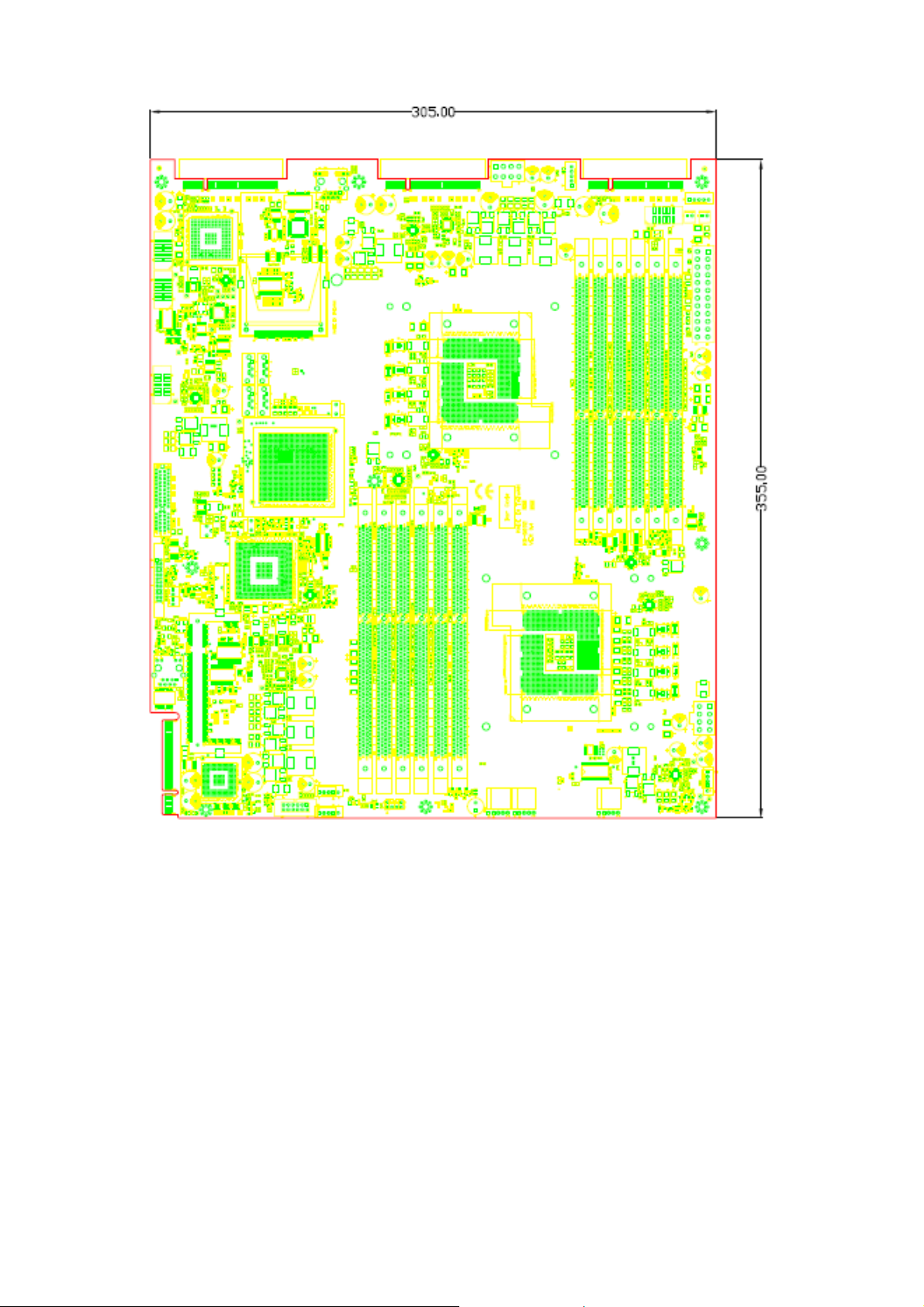
Figure 4 – MB-8892 Dimension
14
Page 15

FW-8892
2.1.2 Jumper Settings and I/O Connectors
The jumper settings and I/O connectors of the MB-8892 board are specific
to the FW-8892. Changing these settings may result in malfunctions or
damage to your system.
15
Page 16

FW-8892
Jumper Settings and I/O Connector Summary for MB-8892:
JUMPER FUNCTION
LANB2
USBA1 ~2 USB Dual Connector
COM1~2 Serial Port #2 Connector ( RS-232 Header )
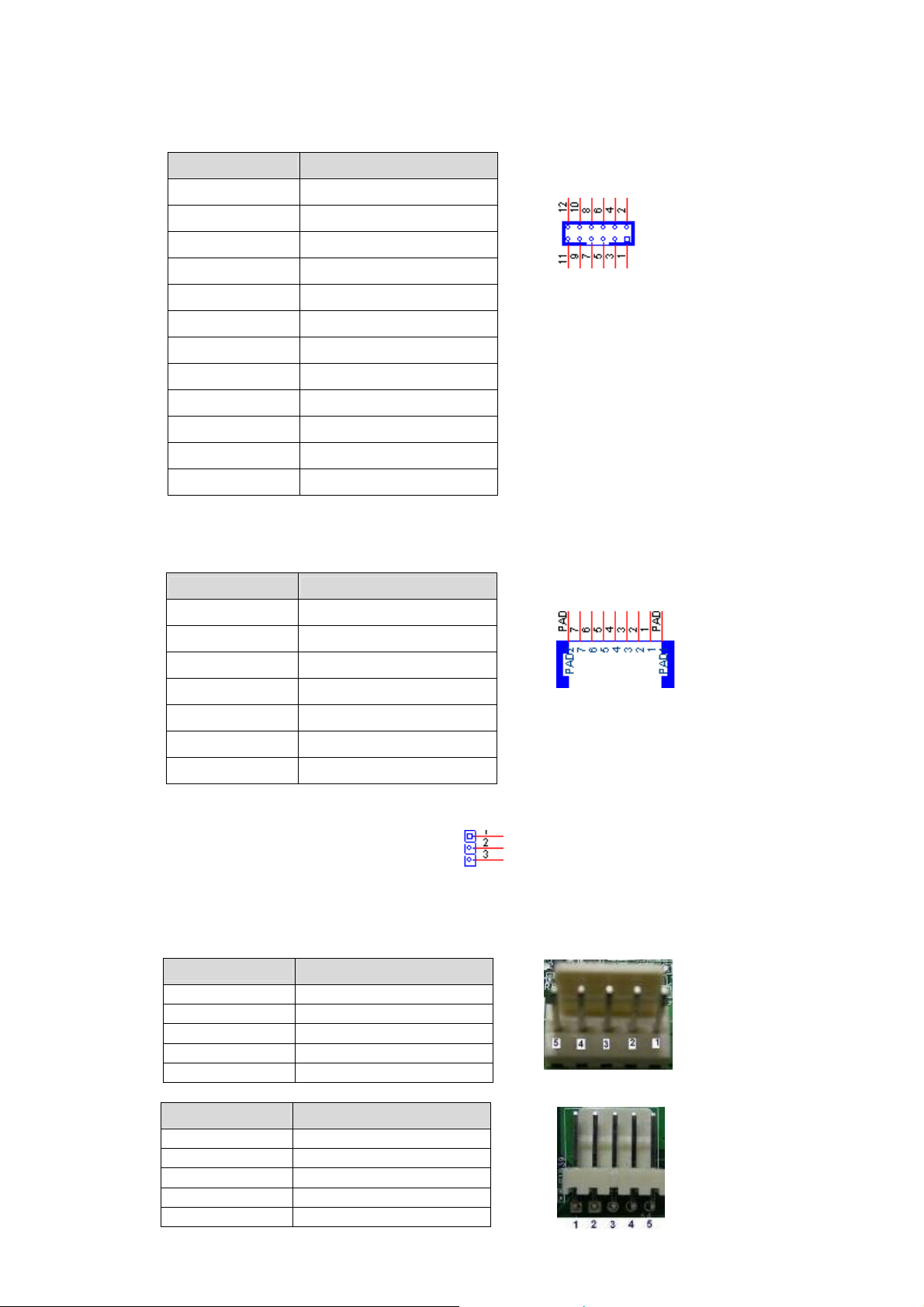
J16 External VGA Connector (12 Pin Header)
SATA1~4 180º SATA CONNECTOR
CCMOS1 Clear CMOS Data
FAN9~14 5-Pin FAN Connector
ATXPWR2 24-Pin ATX Power Connector
ATXPWR1, ATXPWR3 8-Pin ATX Power Connector
CF1 Compact Flash Connector
RJ45 connector for IPMI management
(FW-8892C & FW-8892D only)
CON1 OPMA Connector (For IPMI)
PCIEC1~3 PCI-Ex8 Connector For LAN module
J19 PCI-Ex8 Golden finger For Add-On card
J9 24-Pin LCM Connector
PKMB1 PS/2 KB Mouse Connector
PSW1 Power Switch
PSW2 Reset Button
SPI-ROM1 SPI ROM Interface
PCIE1 PCI-Ex4 Connector (Option)
16
Page 17

FW-8892
2.1.3 Connectors Pin Assignment
z Ethernet Interface
Part reference: LANB2
Bellow shows the pin assignment of the RJ45 connector for Ethernet
LANB2 (For IPMI)
PIN DESCRIPTION
1 A_ETH_TXP
2 A_ETH_TXN
3 A_ETH_RXP
4 ETH_SPEED
5 ETH_LINK
6 A_ETH_RXN
7 FP_LAN_RST_N
8 GND
9 NC
10 NC
11 NC
12 NC
z USB Interface
Part reference: USBA1 (To Front Panel); USBA2 (To Pin Header);
Bellow shows the pin assignment of the USB connector.
PIN DESCRIPTION
1 VCC
2
3 USB_L_2N
4 USB_L_1N
5 USB_L_2P
6 USB_L_1P
7 GND
8 GND
9 GND
10 GND
COM port interface
z
Part reference: COM1; COM2
Bellow shows the pin assignment of the COM port connector.
PIN DESCRIPTION
1 Data Carrier Detect : DCD
VCC
2 Received Data : SIN
3 Transmitted Data : SOUT
4 Data Terminal Ready : DTR
5 Signal Ground : GND
6 Data Set Ready : DSR
7 Request To Send : RTS
8 Clear To Send : CTS
9 Ring In : RI
17
Page 18
FW-8892
z VGA Connector
Part reference: J16
Bellow shows the pin assignment of the VGA connector
PIN DESCRIPTION
1
2 CRT ON
3 GREEN
4 Ground
5 BLUE
6 Ground
7 HSYNC
8 Ground
9 VSYNC
10 Ground
11 DDCCLK
12 DDCDATA
SATA interface
z
Part reference: SATA1~SATA4
Note: SATA1 is optional for CF1
PIN DESCRIPTION
1
2 TX+
RED
Ground
3 TX-
4 Ground
5 RX-
6 RX+
7 Ground
z Clear CMOS connector
Part reference: CCMOS1
1-2: Normal (Default)
2-3: Clear CMOS
z FAN
Part reference: FAN9, 10, 11, 12, 13, 14 (5 Pin connector)
Vertical (FAN9, 11, 14)
PIN
1 GND
2 12V
3 RPM Sense
4 RPM Sense
5 PWM Status
Horizontal (FAN10, 12, 13)
PIN
1 PWM Status
2 RPM Sense
3 RPM Sense
4 12V
5 Ground
DESCRIPTION
DESCRIPTION
18
Page 19

FW-8892
z POWER
24 Pin ATX Power Connector
Part reference: ATXPWR2
PIN DESCRIPTION PIN DESCRIPTION
1 +3.3V 13 +3.3V
2 +3.3V 14 -12V
3 Ground 15 Ground
4 +5V 16 PSON5 Ground 17 Ground
6 +5V 18 Ground
7 Ground 19 Ground
8 Power Good 20 NC
9 Stand-By 5V 21 +5V
10 +12V 22 +5V
11 +12V 23 +5V
12 +3.3V 24 Ground
8 Pin ATX Power Connector
Part reference: ATXPWR1; ATXPWR3
PIN DESCRIPTION
1 GND
2 +12V
3 GND
4 +12V
5 GND
6 +12V
7 GND
8 +12V
z Compact Flash Connector
Part reference: CF1
PIN DESCRIPTION PIN DESCRIPTION
1 GND 26 CD12 DATA3 27 DATA11
3 DATA4 28 DATA12
4 DATA5 29 DATA13
5 DATA6 30 DATA14
6 DATA7 31 DATA15
7 CE1# 32 CE2#
8 A10 33 VS1#
9 OE# 34 IOR#
10 A9 35 IOW#
11 A8 36 WE#
12 A7 37 READY#
13 CFVCC3 38 CFVCC3
14 A6 39 CSEL
15 A5 40 VS2#
16 A4 41 RESET
17 A3 42 WAIT#
18 A2 43 INPACK#
19 A1 44 REG#
20 A0 45 DASP#
21 DATA0 46 DIAG#
22 DATA1 47 DATA8
23 DATA2 48 DATA9
24 WP 49 DATA10
25 CD2- 50 GND
24
13
CF1
19
Page 20

z OPMA connector
Part reference: CON1
PCIE Interface (x8)
z
Part reference: PCIEC1 (x8); PCIEC2 (x8); PCIEC3 (x8) Lan Module Connector
Part reference: J19 (x8) Golden finger
PIN DESCRIPTION PIN DESCRIPTION
Side B Side A
1 +12v 1 PRSNT#1
2 +12v 2 +12v
3 RSVD 3 +12v
4 GND 4 GND
5 SMCLK 5 JTAG2
6 SMDAT 6 JTAG3
7 GND 7 JTAG4
8 +3.3v 8 JTAG5
9 JTAG1 9 +3.3v
10 3.3Vaux 10 +3.3v
11 WAKE# 11 PWRGD
12 RSVD 12 GND
13 GND 13 REFCLK+
14 HSOp(0) 14 REFCLK15 HSOn(0) 15 GND
16 GND 16 HSIp(0)
17 PRSNT#2 17 HSIn(0)
18 GND 18 GND
19 HSOp(1) 19 RSVD
20 HSOn(1) 20 GND
21 GND 21 HSIp(1)
22 GND 22 HSIn(1)
23 HSOp(2) 23 GND
24 HSOn(2) 24 GND
25 GND 25 HSIp(2)
26 GND 26 HSIn(2)
27 HSOp(3) 27 GND
28 HSOn(0) 28 GND
29 GND 29 HSIp(3)
30 RSVD 30 HSIn(3)
31 PRSNT#2 31 GND
32 GND 32 RSVD
33 HSOp(4) 33 RSVD
34 HSOn(4) 34 GND
35 GND 35 HSIp(4)
36 GND 36 HSIn(4)
37 HSOp(5) 37 GND
38 HSOn(5) 38 GND
39 GND 39 HSIp(5)
40 GND 40 HSIn(5)
41 HSOp(6) 41 GND
42 HSOn(6) 42 GND
43 GND 43 HSIp(6)
44 GND 44 HSIn(6)
45 HSOp(7) 45 GND
46 HSOn(7) 46 GND
47 GND 47 HSIp(7)
48 PRSNT#2 48 HSIn(7)
49 GND 49 GND
FW-8892
20
Page 21

FW-8892
z LCM
Part reference: J9
PIN DESCRIPTION PIN DESCRIPTION
1 P5V 13 FL_PD7
2 GND 14 FL_PD6
3 P_SLIN# 15 LCD-
4 VEE 16 P5V
5 P_AFD# 17 KPA1
6 P_INIT# 18 KPA2
7 FL_PD1 19 KPA3
8 FL_PD0 20 KPA4
9 FL_PD3 21 LCM_RST_N
10 FL_PD2 22 CTR_GRN
11 FL_PD5 23 CTR_RED
12 FL_PD4 24 HDD_LED_N
z PKMB1: PS/2 Keyboard & Mouse Connector
Part reference: PKMB1
PIN DESCRIPTION
1 VCC
2 MSCLK
3 MSDATA
4 KEY
5 KBDATA
6 KEY
7 GND
8 KBCLK
z Power /Reset Switch
Part reference: PSW1, PSW2
PSW1 (Power Switch)
PIN DESCRIPTION
1 GND
2 PSW1
PSW2 (Reset Button)
PIN DESCRIPTION
1 GND
2 PSW2
SPI ROM Interface
z
Part reference: SPI-ROM1
Bellow shows the pin assignment of the SPI ROM Interface connector.
PIN DESCRIPTION
1 SPI_HOLD1_L
2 SPI_CS1
3 SPI_CS0
4 P3V3
5 SPI_MISO
6 SPI_HOLD0_L
7 NC
8 SPI_CLK_PRI_SEC
9 GND
10 SPI_MOSI_PRI_SEC
21
Page 22

z PCIE Interface (x4) Æ Option
Part reference: PCIE1
PIN DESCRIPTION PIN DESCRIPTION
Side B Side A
1 +12v 1 PRSNT#1
2 +12v 2 +12v
3 RSVD 3 +12v
4 GND 4 GND
5 SMCLK 5 JTAG2
6 SMDAT 6 JTAG3
7 GND 7 JTAG4
8 +3.3v 8 JTAG5
9 JTAG1 9 +3.3v
10 3.3Vaux 10 +3.3v
11 WAKE# 11 PWRGD
12 RSVD 12 GND
13 GND 13 REFCLK+
14 HSOp(0) 14 REFCLK15 HSOn(0) 15 GND
16 GND 16 HSIp(0)
17 PRSNT#2 17 HSIn(0)
18 GND 18 GND
19 HSOp(1) 19 RSVD
20 HSOn(1) 20 GND
21 GND 21 HSIp(1)
22 GND 22 HSIn(1)
23 HSOp(2) 23 GND
24 HSOn(2) 24 GND
25 GND 25 HSIp(2)
26 GND 26 HSIn(2)
27 HSOp(3) 27 GND
28 HSOn(0) 28 GND
29 GND 29 HSIp(3)
30 RSVD 30 HSIn(3)
31 PRSNT#2 31 GND
32 GND 32 RSVD
FW-8892
22
Page 23

FW-8892
2.2 Mechanical Overview
This section of the manual describes the mechanical and device
nomenclature of FW-8892.
2.2.1 Front View, LED Status and Behavior
Figure 5 - FW-8892 Front View
HDD Tray HDD Tray HDD Tray HDD Tray
Graphic LCM
with Button
USB x2 Console (RJ45)
IPMI
Management
Port (RJ45)
LAN Module LAN Module LAN Module
(1) Graphic LCM Module with buttons
(2) IPMI Management Port
(Option)
(3) Console: The console port cable connects FW-8892 to the host PC via. The
Default baud rate is 9600.
(4) USB: Support two USB devices.
(5) Four External 3.5” HDD Trays
(6) Three LAN module slots which can support Gigabit Copper (RJ-45) /
Optical (SFP) and 10G (SFP+) LAN Module. Max up to twenty-four Gigabit
Ethernet ports
The following table provides description of each LED on the FW-8892 front
panel.
LED Color Status
Green ON Indicates when FW-8892 power is switched ON.
POWER
N/A OFF No power connected
STATUS
HDD
Green
Orange
Yellow ON Hard disk is being accessed
N/A OFF No Data is being accessed
Lanner Provide the Sample Codes(Please
reference the Driver/ Manual CD, under “LED
Status” for more information)
23
Description
Page 24

FW-8892
LED Indicate
on LAN Module
Color Status
Yel low
10/100
Green
Green/
Orange
10/ 100/ 1000
Orange
2.2.2 Rear View
Description
ON When LAN is connecting.
Blinking
When data is accessing.
100M
10M
ON
Green for 100M
Orange for 1000M (GbE)
OFF 10M
ON When LAN is connecting.
Blinking
When data is accessing.
Figure 6 - FW-8892 Rear View
Extend PCI-E Slot
4028
System
FAN
(FAN 8)
4028
System
FAN
(FAN 7)
4056
System
FAN
(FAN 6)
4056
System
FAN
(FAN 5)
4056
System
FAN
(FAN 4)
4056
System
FAN
(FAN 3)
Power
On/ Off
Button
Alarm
Buzzer
Switch
Redundant Power
Supply
(1) Redundant Power Supply
(2) Power On/ Off Button
(3) Alarm Buzzer Switch
(4) Field replaceable System Fans (From right to left: FAN 3~ FAN 8)
FAN 3~ FAN 6: 4056 System Fan
FAN 7~ FAN 8: 4028 System Fan
(5) Extend PCI-E Slot: Support up to two PCI-E expansion cards with riser
card
RC-88921A supports one PCI-Ex8 expansion card.
24
Page 25

FW-8892
RC-88922A supports two PCI-Ex4 expansion cards (one for external
and the other for internal.)
Warning: Faulty or improper use of the power adaptor may cause
permanent damage to the power supply and the FW-8892.
Plug the adaptor to an electrical wall outlet that matches its
specifications.
25
Page 26

FW-8892
3. Hardware Installation Guide
3.1 System Memory
Position the DIMM module to the DIMM socket properly, so the notch on the
memory module first the socket. Push the memory into the socket.
Note: The memory module requires the proper orientation in order to fit into
the socket properly.
3.2 Install the Compact Flash Card
Carefully insert the Compact Flash card into the slot as shown in the
illustration above.
3.3 Din-Rail Rack Mounting
Installation environment precaution:
1. Elevated Operating Ambient - If installed in a closed or multi-unit rack
assembly, the operating ambient temperature of the rack environment may
be greater than room ambient. Therefore, consideration should be given to
installing the equipment in an environment compatible with the maximum
ambient temperature (Tma) specified by the manufacturer.
2. Reduced Air Flow - Installation of the equipment in a rack should be such
that the amount of air flow required for safe operation of the equipment is
not compromised. Mechanical Loading - Mounting of the equipment in the
26
Page 27

FW-8892
rack should be such that a hazardous condition is not created due to uneven
mechanical loading.
3. Circuit Overloading - Consideration should be given to the connection of the
equipment to the supply circuit and the effect that overloading of the
circuits might have on over-current protection and supply wiring.
Appropriate consideration of equipment nameplate ratings should be used
when addressing this concern.
4. Reliable Earthing - Reliable earthing of rack-mounted equipment should be
maintained. Particular attention should be given to supply connections
other than direct connections to the branch circuit (e.g. use of power
strips).”
CAUTION:
Slide/rail mounted equipment is not to be used as a shelf or a work space.
Required tools:
1. Philips (cross head) screwdriver (#1 bit and #2 bit)
2. Anti-static wrist strap and conductive foam pad (recommended)
3. Din-Rail mounting kit contains the following items:
2 outer rails
4 inner rails
4. Crosshead threaded screws
5. The following picture shows the inner rail (top) and the outer rail
(bottom).
Attaching inner rails to the chassis:
Use the following steps to install the inner rails to the chassis:
1. Position the inner rail alongside the side of the system’s chassis with the
finger tab facing outward as shown in the following diagram.
2. Align the screw holes of the rail and the mounting holes of the chassis
and then fix the inner rail to the system with crosshead threaded
screws.
3. Repeat the above steps again to attach another rail on the same side.
4. Attach the front bracket to the system
5. Likewise, attach other inner rails and front bracket to the other side of
system’s chassis.
27
Page 28

FW-8892
Installing the outer rails to the rack:
Use the following procedures to install the outer rail:
1. Attach the rail to the posts of the rack by using three rack screws.
2. Extend the outer back rail to the back of the rack and firmly tighten it
with two rack screws.
3. Repeat step 1 and 2 above to install the other rail.
Installing the system to the rack:
Holding the system with its front facing you, lift the chassis and carefully
insert the system by sliding the inner rail into the outer rail. Push the chassis
all the way toward the back until the front brackets contact the rack. You
may also fix the front brackets to the rack if the system doesn’t require
frequent pulling out of the rack.
28
Page 29

FW-8892
4. BIOS Setup
BIOS Setup
AMI’s ROM BIOS provides a built-in Setup program that allows users to modify the
basic system configuration and settings. The modified data will be stored in a
battery-backed CMOS RAM so that this data will be retained even when the power
is turned off. In general, the information saved in the CMOS RAM remains
unchanged unless there is a configuration change in the system, such as hard drive
replacement or new equipment installment.
Running AMI BIOS
The Setup Utility is stored in the BIOS ROM. When the power of the computer
system is turned on, a screen message will appear to give you an opportunity to call
up the Setup Utility while the BIOS will enter the Power On Self Test (POST)
routines. The POST routines perform various diagnostic checks while initializing the
board hardware. If the routines encounter an error during the tests, the error will
be reported in one of two ways, a series of short beeps or an error message on the
screen. There are two kinds of errors, fatal and non-fatal. The system can usually
continue the boot up sequence with non-fatal errors. Non-fatal error messages
usually appear on the screen along with the following instructions:
“Press <F1> to RESUME”
Write down the message and press the F1 key to continue the boot up sequence.
After the POST routines are completed, the following message appears:
“Press DEL to enter SETUP”
Entering Setup
Turn on the power of the computer system and press <Del> immediately. If you
don’t have the chance to respond, reset the system by simultaneously pressing the
<Ctrl>, <Alt> and <Delete> keys, or by pushing the “Reset” button on the
system cabinet. You can also restart by turning the system OFF then ON.
CMOS Setup Utility
To access the AMI BIOS SETUP program, press the <DEL> key. The screen display
will appears as shown below:
29
Page 30

FW-8892
4.1 Main Program Screen
This screen provides access to the utility‘s various functions.
Listed below is explanation of the keys displayed at the bottom of the screen:
<ESC>: Exit the utility.
< >: ↑↓→ ← Use arrow keys ↑↓→ ← to move cursor to your desired selection.
<F1> : General Help
<F10>: Saves all changes made to Setup and exits program.
Main For changing the basic system configuration
Advanced For changing the advanced system settings.
Boot For changing the system boot configuration
Security For changing the Security setting
Exit For selecting the exit options and loading default settings
30
Page 31

FW-8892
4.2 Main Menu
When you select the “Main Menu” on the main program, the screen display will
appears as:
The Main Meun utility is used to configure the following components such as date,
time, display and memory.
Processor Displays the auto-detected CPU specification
System Memory Displays the auto-detected system memory
System Time [xx:xx:xxxx] Allows you to set the system time.
System Date [Day xx/xx/xxxx] Allows you to set the system date.
31
Page 32

FW-8892
4.3 Advanced Menu
When you select the “Advanced Menu” on the main program, the screen display will
appear as:
The following explains the options for each of the features as listed in the above
menu:
32
Page 33

FW-8892
IDE Configuration:
The items in this menu allow you to set or change the configurations for the IDE
devices installed in the system. Select an item then press <Enter> if you wish to
configure the item.
SATA#1 Configuration:
This is for setting SATA#1 configuration.
Configuration options: [Disable] [Compatible] [Enhanced]
33
Page 34

Configure SATA#1 as:
Configuration options: [IDE] [AHCI]
FW-8892
SATA#2 Configuration:
This is for setting SATA#2 configuration.
Configuration options: [Disable] [Compatible] [Enhanced]
34
Page 35

Primary IDE Master:
FW-8892
Type:
Selects the type of IDE drive. Setting to Auto allows automatic selection of the
appropriate IDE device type. Select CDROM if you are specifically configuring a
CD-ROM drive. Select ARMD (ATAPI Removable Media Device) if your device is
either a ZIP, LS-120, or MO drive.
Configuration options: [Not Installed] [Auto] [CDROM] [ARMD]
LBA/ Large Mode:
Enables or disables the LBA mode. Setting to Auto enables the LBA mode if the
device supports this mode, and if the device was not previously formatted with LBA
mode disabled.
Configuration options: [Disabled] [Auto].
Block (Multi-sector Transfer):
Enables or disables data multi-sectors transfers. When set to Auto, the data
transfer from and to the device occurs multiple sectors at a time if the device
supports multi-sector transfer feature. When set to [Disabled], the data transfer
from and to the device occurs one sector at a time.
Configuration options: [Disabled] [Auto].
PIO Mode:
Selects the PIO mode.
Configuration options: [Auto] [0] [1] [2] [3] [4].
DMA Mode:
Selects the DMA mode.
35
Page 36

FW-8892
Configuration options: [Auto] [DMA0][SWDMA1] [SWDMA2] [MWDMA0]
[MWDMA1] [MWDMA2] [UDMA0] [UDMA1] [UDMA2] [UDMA3] [UDMA4] [UDMA5].
SMART Monitoring:
Sets the Smart Monitoring, Analysis, and Reporting Technology.
Configuration options: [Auto] [Disabled] [Enabled].
32Bit Data Transfer:
Enables or disables 32-bit data transfer.
Configuration options: [Disabled] [Enabled].
36
Page 37

FW-8892
Super IO Configuration:
Press <Enter> to enter the sub-menu and the following screen appears:
Serial Port1/2 Address:
These items specify the base I/O port addresses of the onboard Serial Port 1.
Selecting [Auto] allows BIOS to automatically determine the correct base I/O port
address.
Settings: [3F8/IRQ4], [2F8/IRQ3], [3E8/IRQ4], [2E8/IRQ3] and [Disabled].
Parallel Port Address:
Allows you to select the Parallel Port base addresses.
Configuration options: [Disabled] [378] [278] [3BC].
Parallel Port Mode:
Allows you to select the Parallel Port mode.
Configuration options: [Normal] [Bi-directional] [EPP] [ECP].
Parallel Port IRQ:
Configuration options: [IRQ5] [IRQ7].
37
Page 38

FW-8892
Hardware Health Configuration:
Press <Enter> to enter the sub-menu and the following screen appears:
H/W Health-Temperature and FAN speed:
Enable/Disable Hardware Health Monitoring Device.
38
Page 39

FW-8892
H/W Health-SMART FAN Control:
These items allow you to select system fan control mode & set the Target
Temperature Value.
Configuration options: [Thermal Mode] [Full Speed]
Target Temperature Value: [XXX]
39
Page 40

FW-8892
H/W Health Voltage:
These items allows you to set 1.5V, 3.3V, 12V and 5V voltage
40
Page 41

FW-8892
USB Configuration:
Press <Enter> to enter the sub-menu and the following screen appears:
USB Function:
Allows you to enable or disable support for USB ports.
Configuration options: [Enable] [Disable].
USB2.0 Controller:
Enabled/ Disabled USB 2.0 spec.
Configuration options: [Enabled] [Disabled]
Legacy USB Support:
Enables support for legacy USB. AUTO option disables legacy support if no USB
devices are connected.
Configuration options: [Disable] [Enable] [Auto].
USB 2.0 Controller Mode:
Configures the USB 2.0 controller in Hi-Speed or Full-Speed.
Configuration options: [FullSpeed] [HiSpeed].
41
Page 42

FW-8892
USB Mass Storage Device Configuration:
To set the number of seconds POST waits for the USB mass storage device after
start unit command.
42
Page 43

FW-8892
Remote Access Configuration:
Press <Enter> to enter the sub-menu and enable Remote Access then the following
screen appears:
Serial port number:
Select Serial Port for console redirection.
Serial Port Mode:
Select Serial Port setting.
Flow Control:
Select Flow Control for console redirection.
Redirection After BIOS POST:
DISABLE, Turns off the redirection after POST. Boot Loader, Redirection is active
during POST and during Boot Loader. Always, Redirection is always active.
Terminal Type:
Select the target terminal type.
VT-UTF8 Combo Key Support:
Enable VT-UTF8 Combination Key Support for ANSI/VT100 terminals.
Sredir Memory Display Delay:
Gives the delay in seconds to display memory information.
43
Page 44

FW-8892
Restore on AC power loss by:
Select Power Status.
Configuration options: [Power Off] [Power On] [Last State].
Clock Gen Differential Output:
Select Differential Output Voltage.
Configuration options: [0.8V] [0.9V] [1.0V].
44
Page 45

FW-8892
Power Off LAN bypass
Press <Enter> to select the Power Off LAN bypass status:
Configuration options: [Disable] [Enabled].
45
Page 46

FW-8892
4.4 Boot Menu
The Boot menu items allow you to change the system boot options. Select an item
then press <Enter> to display the sub-menu.
Boot Setting Configuration: Press <Enter> to enter the sub-menu and the
following screen appears:
Quick Boot:
(POST) while booting to decrease the time needed to boot the system. When set to
[Disabled], BIOS performs all the POST items.
Configuration options: [Disabled] [Enabled]
Quiet Boot:
Displays OEM Logo instead of POST messages.
Add On ROM Display Mode:
Configuration options: [Force BIOS] [Keep Current].
Enabling this item allows the BIOS to skip some power on self tests
If disabled then Displays normal POST messages. If enabled then
Sets the display mode for option ROM.
Bootup Num-Lock: Allows you to select the power-on state for the NumLock.
Configuration options: [Off] [On]
46
Page 47

FW-8892
PS/2 Mouse Support: Allows you to enable or disable support for PS/2 mouse.
Configuration options: [Disabled] [Enabled] [Auto].
Wait for ‘F1’ If Error: When set to Enabled, the system waits for the F1 key to be
pressed when error occurs. Configuration options: [Disabled] [Enabled].
Hit ‘DEL’ Message Display: When set to Enabled, the system displays the
message “Press DEL to run Setup” during POST.
Configuration options: [Disabled] [Enabled].
Interrupt 19 Capture: When set to [Enabled], this function allows the option
ROMs to trap Interrupt 19.
Configuration options: [Disabled] [Enabled].
Boot Device Priority: Press <Enter> to enter the sub-menu and the following
screen appears:
1st ~ xxth Boot Device: These items specify the boot device priority sequence
from the available devices. The number of device items that appears on the screen
depends on the number of devices installed in the system.
Configuration options: [xxxxx Drive] [Disabled].
47
Page 48

FW-8892
4.5 Security Menu
Press <Enter> to enter the sub-menu and the following screen appears:
Type the password, up to 6 characters in length, and press <Enter>. The password
typed now will replace any previously set password from CMOS memory. You will be
prompted to confirm the password. Retype the password and press <Enter>. You
may also press <Esc> to abort the selection and not enter a password.
To clear a set password, just press <Enter> when you are prompted to enter the
password. A message will show up confirming the password will be disabled. Once
the password is disabled, the system will boot and you can enter Setup without
entering any password.
When a password has been set, you will be prompted to enter it every time you try
to enter Setup. This prevents an unauthorized person from changing any part of
your system configuration.
Change Supervisor Password: Install or Change the password.
Change User Password: Install or Change the password.
Clear User Password: Clear the password.
48
Page 49

FW-8892
4.6 Exit Menu
Press <Enter> to enter the sub-menu and the following screen appears:
Save Changes and Exit: Once you are finished making your selections, choose
this option from the Exit menu to ensure the values you selected are saved to the
CMOS RAM. An onboard backup battery sustains the CMOS RAM so it stays on even
when the PC is turned off. When you select this option, a confirmation window
appears. Select Yes to save changes and exit.
Discard Changes and Exit: Select this option only if you do not want to save the
changes that you made to the Setup program. If you made changes to fields other
than System Date, System Time, and Password, the BIOS asks for a confirmation
before exiting.
Discard Changes: This option allows you to discard the selections you made and
restore the previously saved values. After selecting this option, a confirmation
appears. Select Yes to discard any changes and load the previously saved values.
Load Optimal Defaults: This option allows you to load the default values for each
of the parameters on the Setup menus. When you select this option or if you press
<F9>, a confirmation window appears. Select Yes to load default values. Select Exit
& Save Changes or make other changes before saving the values to the non-volatile
RAM.
49
Page 50

FW-8892
Appendix A: Power Supply
A.1 Power Supply Specifications
Input specifications:
Output specifications:
50
Page 51

FW-8892
A.2 Feature
• Total output is 500W and 80% efficiency
• Temperature Range: Operating ranges from 0 to 40 , Storage ℃℃
ranges from -20 to 80℃℃
• Dual EMI Noise Inlet Filter: CE Class B, FCC Class B
• AC Inlet in each module
51
Page 52

FW-8892
Appendix B: Watchdog Timer
B.1 Introduction
Most systems need to be self-reliant. If an error should occur it is typically
not possible to wait for the system to be rebooted manually. In some cases,
such as apace probes, the system is simply disabled. In other cases, the
speed at which a human operator would reset the system would be too slow
to meet the uptime requirements of the product.
A watchdog timer is a piece of hardware that can be used to automatically
detect system anomalies and reset the processor if the case any problems
are found. Generally speaking, a watchdog timer is based on a counter that
counts down from an initial value to zero. The software selects the counter's
initial value and periodically restarts it. Should the counter reach zero
before the software restarts it, the software is presumed to be
malfunctioning and the processor's reset signal is asserted. Thus, the
processor will be restarted as if a human operator had cycled the power
Note: Lanner provides sample codes in the Manual/ Driver CD under the
path:// WATCHDOG
52
Page 53

FW-8892
Appendix C: Console Redirection
Console redirection lets you maintain a system from a remote location by
re-directing keyboard input and text output through the serial port. This
section will tell you how to use this feature.
1. Attach the console cable to the FW-8892 and Remote Client System.
2. Choose the following settings in the BIOS Setup menu for FW-8892.
BIOS > Advanced > Remote Access Configuration > Serial Port Mode > [9600, 8, n,
1 ] (Default)
3. Configure Console Redirection on the client system. The following
example is applicable for a Windows platform:
A. Click the start button, point to Programs > Accessories >
Communications and select Hyper Terminal.
B. Enter any name for the new connection and select any icon.
C. Click OK.
D. From the “Connect to”. Pull-down menu, select a Com port
available on the client system and click OK.
E. Select Baud Rate > 9600 > Flow Control > None.
F. Select Data bit > 8.
G. Select Parity Check > None.
H. Select Stop bit > 1.
I. Power on the FW-8892, and it should display the BIOS information
on the client system..
53
Page 54

FW-8892
D. Appendix D: LCM Module and Keypad
for FW-8892
D.1 Purpose of this chapter
The purpose of this document is to provide installation information for the
LCM module and key pad installed in the FW-8892
D.2 LCM module specification overview
The LCM module is designed to provide real-time operating status and
configuration information for the system. The detail specifications can be
referenced in the
Manual/ Driver CD under the path:// Sample_code/Graphic LCM
54
Page 55

FW-8892
E. Appendix E: LAN Bypass Function
E.1 Introduction
The bypass function is used to link (or short) two independent Ethernet
ports when the system crash or powers off. This means if your system is
equipped with a LAN Bypass function, a condition in your system will not
interrupt your network traffic. There are typically two communication states
for the bypass function, one is “Normal” state and another is “Bypass” state.
Lanner provides three methods for enabling the LAN Bypass function.
1. When the system powers off, it will be forced to enable the LAN Bypass
function directly. (You can control this functioin by BIOS to enable or
Disable it).
[BIOS] Æ [Advanced] Æ [LAN Bypass when power off] Æ[Enable/Disable]
2. User can enable or disable the LAN Bypass function by programming
which Control by GPIO.
3. A watchdog timer(WDT)can be used to control the LAN Bypass
function via programming.
Please refer to the Manual/ Driver CD under the path//Sample_code. Lanner
also provides sample code for reference.
55
Page 56

FW-8892
F. Appendix F: Hot Swap System FAN
F.1 Independent Hot Swap System FAN
Hot swap allows devices to be removed and inserted while the system is
running. The system FAN can be swapped independently.
Step1. Open the FAN bracket cover
Step2. Plug out the FAN module
56
Page 57

FW-8892
Terms and Conditions
Warranty Policy
1. All products are under warranty against defects in materials and workmanship for
a period of one year from the date of purchase.
2. The buyer will bear the return freight charges for goods returned for repair within
the warranty period; whereas the manufacturer will bear the after service freight
charges for goods returned to the user.
3. The buyer will pay for repair (for replaced components plus service time) and
transportation charges (both ways) for items after the expiration of the warranty
period.
4. If the RMA Service Request Form does not meet the stated requirement as listed
on “RMA Service,” RMA goods will be returned at customer’s expense.
5. The following conditions are excluded from this warranty:
Improper or inadequate maintenance by the customer
Unauthorized modification, misuse, or reversed engineering of the product
Operation outside of the environmental specifications for the product.
RMA Service
Requesting a RMA#
1. To obtain a RMA number, simply fill out and fax the “RMA Request Form” to your
supplier.
2. The customer is required to fill out the problem code as listed. If your problem is
not among the codes listed, please write the symptom description in the remarks box.
3. Ship the defective unit(s) on freight prepaid terms. Use the original packing
materials when possible.
4. Mark the RMA# clearly on the box.
Note: Customer is responsible for shipping damage(s) resulting from inadequate/loose packing of the
defective unit(s). All RMA# are valid for 30 days only; RMA goods received after the effective RMA#
period will be rejected.
57
Page 58

FW-8892
RMA Service Request Form
When requesting RMA service, please fill out the following form. Without
this form enclosed, your RMA cannot be processed.
RMA No:
Company: Contact Person:
Phone No. Purchased Date:
Fax No.: Applied Date:
Return Shipping Address:
Shipping by: □ Air Freight □ Sea □ Express ___
□ Others:________________
Item Model Name Serial Number Configuration
Item
Problem
Code
Failure Status
Reasons to Return: □ Repair(Please include failure details)
□ Testing Purpose
*Problem Code:
01:D.O.A.
02: Second Time
R.M.A.
03: CMOS Data
Lost
04: FDC Fail
05: HDC Fail
06: Bad Slot
Request Party
Authorized Signature / Date Authorized Signature / Date
07: BIOS Problem
08: Keyboard Controller
Fail
09: Cache RMA Problem
10: Memory Socket Bad
11: Hang Up Software
12: Out Look Damage
13: SCSI
14: LPT Port
15: PS2
16: LAN
17: COM Port
18: Watchdog Timer
Confirmed By Supplier
19: DIO
20: Buzzer
21: Shut Down
22: Panel Fail
23: CRT Fail
24: Others (Pls specify)
58
 Loading...