

Page 1

FW-8750
Manual
Page 2

FW-8750
FW-8750
Manual
Copyright 2008, Lanner Electronics, Inc. All rights reserved. This
document contains proprietary information that is protected by copyright.
No part of this document may be reproduced, transmitted, transcribed,
stored in a retrieval system, or translated into any language in any form by
any means without the written express of Lanner Electronics, Inc.
The author and Lanner Electronics, Inc. have used their best efforts in
preparing this manual. However, the author and Lanner Electronics, Inc.
make no warranties of any kind, expressed or implied, with regard to the
informational content, documentation, or files contained in this manual, and
shall not be liable for technical or editorial errors or omissions contained
herein. In no event shall the author or publisher be responsible or liable for
any incidental or consequential damages resulting from the furnishing,
performance, or use of this material.
TRADEMARKS Internet Explorer, Windows Explorer, and Windows are
trademarks or registered trademarks of Microsoft Corporation. Other
products mentioned herein may be trademarks/or registered trademarks of
their respective owners.
2
Page 3

FW-8750
Safety Guidelines
Follow these guidelines to ensure general safety:
z Keep the chassis area clear and dust-free during and after installation.
z Do not wear loose clothing or jewelry that could get caught in the
chassis. Fasten your tie or scarf and roll up your sleeves.
z Wear safety glasses if you are working under any conditions that might
be hazardous to your eyes.
z Do not perform any action that creates a potential hazard to people or
makes the equipment unsafe.
z Disconnect all power by turning off the power and unplugging the power
cord before installing or removing a chassis or working near power
supplies
z Do not work alone if potentially hazardous conditions exist.
z Never assume that power is disconnected from a circuit; always check
the circuit.
Operating Safety
z Electrical equipment generates heat. Ambient air temperature may not
be adequate to cool equipment to acceptable operating temperatures
without adequate circulation. Be sure that the room in which you
choose to operate your system has adequate air circulation.
z Ensure that the chassis cover is secure. The chassis design allows
cooling air to circulate effectively. An open chassis permits air leaks,
which may interrupt and redirect the flow of cooling air from internal
components.
Electrostatic discharge (ESD) can damage equipment and impair electrical
circuitry. ESD damage occurs when electronic components are improperly
handled and can result in complete or intermittent failures. Be sure to follow
ESD-prevention procedures when removing and replacing components to
avoid these problems.
z Wear an ESD-preventive wrist strap, ensuring that it makes good skin
contact. If no wrist strap is available, ground yourself by touching the
metal part of the chassis.
z Periodically check the resistance value of the antistatic strap, which
should be between 1 and 10 megohms (Mohms).
3
Page 4

FW-8750
EMC Notice
This equipment has been tested and found to comply with the limits for a
Class A digital device, pursuant to Part 15 of the FCC Rules. These limits are
designed to provide reasonable protection against harmful interference
when the equipment is operated in a commercial environment. This
equipment generates, uses, and can radiate radio frequency energy and, if
not installed and used in accordance with the instruction manual, may cause
harmful interference to radio communications. Operation of this equipment
in a residential area is likely to cause harmful interference in which case
users will be required to correct the interference at their own expense.
Class A Notice for FCC
Modifying the equipment without the authorization of Lanner Electronics,
Inc. may result in the equipment no longer complying with FCC
requirements for Class A digital devices. In that event, your right to use the
equipment may be limited by FCC regulations, and you may be required to
correct any interference to radio or television communications at your own
expense.
This equipment is in compliance with the essential requirements and other
relevant provisions of Directive 1999/5/EC.
4
Page 5

FW-8750
Contents
Safety Guidelines .......................................................................3
EMC Notice ................................................................................. 4
Contents.....................................................................................5
1. Product Overview ................................................................. 7
1.1 Product Introduction ................................................................... 7
1.2 Features and Benefits .................................................................. 8
1.3 Specifications .............................................................................. 9
1.4 Package Contents ...................................................................... 10
1.5 Technical Assistance.................................................................. 10
2. System Components ........................................................... 11
2.1 EM-8675 system Board ............................................................ 11
2.1.1 Board Layout ...................................................................11
2.1.2 Dimensions (mm) .............................................................12
2.1.3 Jumper Settings and I/O Connectors ...................................13
2.1.4 Connectors Pin Assignment ................................................14
PKMB1
CCMOS2: Clear CMOS Data ..............................................................14
USBF1
CN1
JFPIO1
CPUFAN1~3
NBFAN1
JP1
ATX1
ATX12V1
J1
COM2
LCMKPK1
2.2 Mechanical Overview................................................................ 21
2.2.1 Front View, LED Status and Behavior .................................21
2.2.2 Rear View........................................................................22
3. Hardware Installation Guide ................................................23
3.1 CPU installation........................................................................ 23
3.2 System Memory........................................................................ 23
3.3 Install the Compact Flash Card ................................................ 24
:2x4 Header PS/2 Keyboard & Mouse Connector.......................14
:2 x 5 Pin USB Interface Header (2.54mm) ............................15
:Compact Flash Connector ........................................................16
:9Pin Front Panel Connector (2.54mm) ...................................16
/SYSFAN1:3Pin Smart FAN Header.................................17
:3 Pin FAN Header..............................................................17
:2 Pin ATX Power Switch Header (2.54mm) ..................................18
:24 Pin Power Connector........................................................18
:2 x 20 Pin BOX Connector (2.0mm) .................................19
:External VGA Connector (12 Pin Header) ...................................19
:9 Pin Serial Interface Header (2.54mm) ...............................20
:24Pin LCM Interface Header (2.0mm) ................................20
4. BIOS Setup...........................................................................25
4.1 Main Program Screen.................................................................... 26
4.2 Main CMOS Setup.......................................................................... 27
4.3 Advanced Menu............................................................................. 28
4.4 Boot Menu .....................................................................................33
4.5 Security Menu............................................................................... 35
4.6 Chipset Menu................................ .................................................36
4.7 Exit Menu.......................................................................................37
A. Appendix A: Power Supply ...................................................38
A.1 Power Supply Specifications...................................................... 38
5
Page 6

FW-8750
A.2 Feature...................................................................................... 38
B. Appendix B: Watchdog Timer ...............................................39
B.1 Introduction .............................................................................. 39
C. Appendix C: Console Redirection..........................................40
D. Appendix D: LCM Module and Keypad for FW-8890 ..............41
D.1 Purpose of this chapter ............................................................. 41
D.2 LCM module specification overview........................................... 41
D.3 Installing the LCM driver for Windows 2000/ XP ...................... 41
D.4 Installing the LCM Driver for Linux............................................ 41
D.5 LCM & KeyPad Function Library Description.............................. 41
E. Appendix E: LAN Bypass Function.........................................42
E.1 Introduction .............................................................................. 42
F. Appendix F: Hot swap...........................................................43
F.1 Introduction .............................................................................. 43
Terms and Conditions...............................................................44
Warranty Policy ................................................................................. 44
RMA Service ........................................................................................44
Requesting a RMA#.........................................................................44
RMA Service Request Form...............................................................45
6
Page 7

FW-8750
1. Product Overview
1.1 Product Introduction
Figure 1 - FW-8750B Outlook
Built around the Intel Q35 chipset, the FW-8750 is the High benchmark for
performance and throughput in a network appliance. Supporting Quad-Core
/Dual-Core/Single-Core series processors in LGA775 socket the FW-8750
delivers fantastic performance per Watt.
The optional Cavium Nitrox CN1610 processes high-level IPsec and IKE,
IPv6, SSL and Wireless LAN security protocol macro commands, that reduce
the host I/O traffic and dramatically offload system processors to increase
the total system throughput.
With one expansion module, Two unbuffered Dual-channel DDRII RAM
Dimms, the FW-8750 offers customization now and plenty of headroom for
hardware expansion in the future. Moreover, Lanner provides full-service
product customization by working with you from drawings to samples to
mass production to create a product that meets your exact specifications.
7
Page 8

FW-8750
1.2 Features and Benefits
Listed below are the key features of FW-8750:
• High-performance Intel Q35 desk-top architecture with LGA 775 for
Dual-Core and Quad-Core processor support
• Supports up to ten Gigabit Ethernet ports with Intel 82573L/82574L
chipset and dedicated PCI-E x 2 bus per GbE pair
• Embedded Cavium CN1610 delivers high-speed encryption and packet
throughput
• Supports two Dual Channel DDRII 667/800, and up to 4GB
• Equipped with Type II Compact Flash socket, Console port, USB Ports,
PCI slot for used.
• Customization of the front panel and chassis colors ensures tailored
solutions for OEM and ODM customers
8
Page 9

FW-8750
1.3 Specifications
FEATURE DESCRIPTION
Form Factor Desktop
Platform
Storage Interface Storage Interface 1 x Compact Flash Type II socket
Modules
Expansion PCI RC-87501A:1 x PCI slot
Cooling
Environmental
Parameters
Processor
Front Side Bus 800/1066/1333 MHZ
Chipset Intel®Q35Chipset(MCH),Intel®ICH9D
BIOS AMI BIOS
Technology DDR-II 667/800MH System Memory
Max Capacity 4 GB (2 DIMM sockets)
Ethernet Ports 6 x RJ45 GbE ports,two pair of bypass
Controller 5xIntel 82573L chip
Console DB-9 RS-232 connector x 1 Front I/O Interface
USB 2.0 2
Processor Heat Sink
System 1 x System FAN
Temperature, Ambient
operating
Temperature, Ambient
storage
Humidity, Ambient
operating and
non-operating
Dimensions(W x H x D) 431 x 44 x 395 mm Physical Dimensions
Weight N.W.: 8.2 kg./ G.W.: 10 kg.
Type/ Watts 270W Power
Input AC 100~240V@50~60Hz
re 2 Quad/Dual Core/Core 2 Duo
/Pentium 4/Celeron 400 in LGA775
sockets
OI/O Controller Hub
4 x SATA II connectors
1xIntel 82566DM chip
3 x CPU FAN
0℃~40℃
-20℃~70℃
5~95%, non condensing
Approvals & Compliance CE (EMC), FCC Class A
Windows 2000, 2003, XP O.S. support
Linux Kernal 2.6 or above
9
Page 10

FW-8750
1.4 Package Contents
Carefully unpack your package and make sure that you have the below items.
• FW-8750 Network Security Platform x 1
• Console cable(DB9)x 1
• 1.8 meters long cross-over Ethernet cable x 1
• 1.8 meters long straight-through Ethernet cable x 1
• Name Plate label(Front Panel)x 1
• Power cable x 1
• Drivers and User’s Manual CD x 1
• Screw Set
Note:If you should find any components missing or damaged, please
contact your dealer immediately for assistance
1.5 Technical Assistance
Should you have any questions or problems with your product, please
contact the Lanner sales team.
Phone: 886-2-8692-6060
Fax: 886-2-8692-6101
E-mail: sales@lannerinc.com
Prior to contacting us, we ask that you first check the electronic product
documentation for assistance. Should you still have questions, we
recommend you have the following information on hand in order to expedite
the process:
1. FW-8750 model name
2. Part number
3. Abnormal behavior and/or error messages reported by your network
system
4. Your questions or a description of the problem you are experiencing
10
Page 11
FW-8750
2. System Components
2.1 MB-8750 system Board
EM-8750 is the system board bundled with the FW-8750 Network security
platform. The succeeding sections list all EM-8750 related jumper settings
and connector pin assignments.
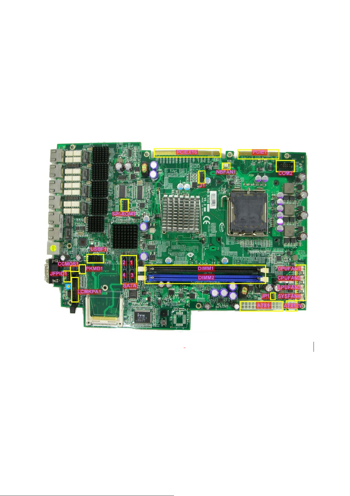
2.1.1 Board Layout
Figure 2 – EM-8750
Key Features
11
Page 12
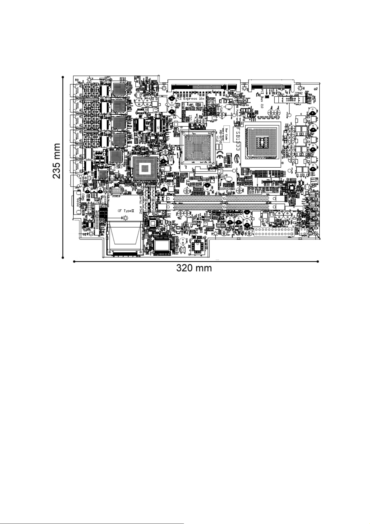
2.1.2 Dimensions (mm)
FW-8750
Figure 3 – Dimensions
12
Page 13

FW-8750
2.1.3 Jumper Settings and I/O Connectors
The jumper settings and I/O connectors of the MB-8750 board are specific
to the FW-8750. Changing these settings may result in malfunctions or
damage to your system.
Jumper Settings and I/O Connector Summary for MB-8750:
JUMPER FUNCTION
PKMB1 2x4 Header PS/2 Keyboard & Mouse Connector (2.54mm)
CCMOS1 Clear CMOS Data
USBF1 2x5 Pin USB Interface Header (2.54mm)
CN1 Compact Flash Connector
JFPIO1 9 Pin Front Panel Connector (2.54mm)
CPUFAN1~3/SYSFAN4
NBFAN1 3 Pin FAN Header
JP1 2 Pin ATX Power Switch Header
ATX1 2x12 Pin Power Connector
ATX12V1 2x2 Pin 12V Power Connector
J1 2x6 Pin External VGA Header (2.0mm)
COM2 9 Pin Serial Interface Header (2.54mm)
LCMKPA1 2x12 Pin LCM Interface Header (2.0mm)
SATA1~SATA4 SATA Connector
PCIEX16 PCI Express x16 Standard Connector
PCIE1 PCI Connector
DIMM1~DIMM2 240Pin Long-DIMM Connector
3 Pin Smart FAN Header
13
Page 14
FW-8750
2.1.4 Connectors Pin Assignment
PKMB1:2x4 Header PS/2 Keyboard & Mouse Connector
8
2
7
5
3
1
PIN NO. DESCRIPTION PIN NO. DESCRIPTION
1 VCC5 2 MSCLK
3 MSDATA 4 KEY
5 KBDATA 6 KEY
7 GND 8 KBCLK
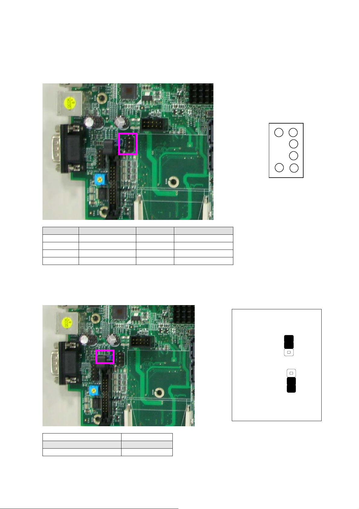
CCMOS1: Clear CMOS Data
CCMOS1
Clear CMOS1
1
2
3
1
2
3
DESCRIPTION CMOS
Normal (Default) 1-2
Clear CMOS 2-3
14
Page 15

FW-8750
USBF1:2x5 Pin USB Interface Header (2.54mm)
3 17 5 9
4 28 6 10
PIN NO. DESCRIPTION PIN NO. DESCRIPTION
1
3
5
7
VCC_0
N.C.
USB_0USB_0+
2
4
6
8
VCC_0
N.C.
USB_0USB_0+
CN1:Compact Flash Connector
CN1
15
Page 16

FW-8750
PIN No. DESCRIPTION PIN No. DESCRIPTION
1 Ground 26 CF_DIS#
2 CF_DD3 27 CF_DD11
3 CF_DD4 28 CF_DD12
4 CF_DD5 29 CF_DD13
5 CF_DD6 30 CF_DD14
6 CF_DD7 31 CF_DD15
7 -CF_DCS0 32 -CF_DCS1
8 Ground 33 VCC3
9 Ground 34 CF_DIOR#
10 Ground 35 CF_DIOW#
11 Ground 36 VCC3
12 Ground 37 CF_IDEIRQ
13 VCC3 38 VCC3
14 Ground 39 Ground
15 Ground 40 VCC3
16 Ground 41 CF_IDERST#
17 Ground 42 CF_IORDY
18 CF_DA2 43 CF_DMARQ
19 CF_DA1 44 CF_DDACK#
20 CF_DA0 45 CFACT_L
21 CF_DD0 46 CF_PDIAG
22 CF_DD1 47 CF_DD8
23 CF_DD2 48 CF_DD9
24 N/C Pin 49 CF_DD10
25 CF_DIS# 50 Ground
JFPIO1:9Pin Front Panel Connector (2.54mm)
PIN NO DESCRIPTION PIN NO DESCRIPTION
1
3
5
7
9
VCC5
HDD_LED
GND
RSTSW
N/C
2
4
6
8
5VSB
SUSLED(POWER_LED)
(GND)
POWON(PWRBTN)
1
2
3
4
5
6
7
8
9
16
Page 17

FW-8750
CPUFAN1~3/SYSFAN1:3Pin Smart FAN Header
1 2 3
PIN NO DESCRIPTION
1 Ground
2 VFAN1~2
3 FAN1~2
NBFAN1:3 Pin FAN Header
1 2 3
PIN NO DESCRIPTION
1 Ground
2 VFAN4(+12V)
3 DUMMY
17
Page 18

FW-8750
JP1:2 Pin ATX Power Switch Header
PIN NO DESCRIPTION
1 PS_ON SW
2 PS_ON
ATX1:24Pin Power Connector
JP1
1
2
PIN NO. DESCRIPTION PIN NO. DESCRIPTION
1 3.3V 13 3.3V
2 3.3V 14 -12V
3 GND 15 GND
4 VCC5 16 PS_ON
5 GND 17 GND
6 VCC5 18 GND
7 GND 19 GND
8 ATX_PWROK 20 -5V
9 5VSTBY 21 VCC5
10 12V 22 VCC5
11 12V 23 VCC5
12 3.3V 24 GND
18
Page 19

FW-8750
ATX12V1:2 x 20 Pin BOX Connector (2.0mm)
PIN NO. DESCRIPTION
1 GND
2 GND
3 +12V
4 +12V
J1: External VGA Connector (12 Pin Header)
PIN NO. DESCRIPTION PIN NO. DESCRIPTION
1 VGA_R 2 Ground
3 VGA_G 4 Ground
5 VGA_B 6 Ground
7 HSYNC_3V N/C
9 VSYNC_3V 10 Ground
11 DD_DATA 12 DD_CLK
1
12 2
11
19
Page 20

FW-8750
COM2:9 Pin Serial Interface Header (2.54mm)
9
PIN NO. DESCRIPTION PIN NO. DESCRIPTION
1 COM2_1 2 NDSR2
3 COM2_2 4 NRTS2
5 COM2_3 6 NCTS2
7 COM2_4 8 COMP2POWER
9 GND 10 NC
LCMKPK1:24 Pin LCM Interface Header (2.0mm)
3 1 7 5
4 2 8 6
PIN NO. DESCRIPTION PIN NO. DESCRIPTION
1 VCC5 2 GND
3 SLIN / LPT17 4 VEE
5 AFD- / LPT14 6 PINIT / LPT16
7 PD1 / LDB1 8 PD0 / LDB0
9 PD3 / LDB3 10 PD2 / LDB2
11 PD5 / LDB5 12 PD4 / LDB4
13 PD7 / LDB7 14 PD6 / LDB6
15 STB- / LCD- 16 VCC5
17 KPA1 / LERR_L 18 KPA2 / LSLCT
19 KPA3 / LPE 20 KPA4 / LBUSY
21 3VSB / RST_BTN_L 22 LED GRN/ STATUS
23 LED RED/ STATUS 24 HDD_LED/ STATUS
20
Page 21

FW-8750
r
2.2 Mechanical Overview
This section of the manual describes the mechanical and device
nomenclature of FW-8750..
2.2.1 Front View, LED Status and Behavior
LAN Connecto
USB
Console
Figure 4 - FW-8750 Front View
LED Status
Key Pad
The following table provides description of each LED on the FW-8750 front panel.
• Console Port: The console port cable connects FW-8750 to the
host PC via. The Default baud rate is 115200
• LAN Connector: Require an Ethernet RJ-45 cable
• LCM & Keypad: Please reference the Appendix B
LED Color Status
PWR
HDD
Ethernet Ports
Link/ACT
Status Lanner Provide the Sample Codes(Please
Green
N/A Off No power connected
Yellow On Hard disk is being accessed
N/A Off No Data is being accessed
Green On LAN is connected
Orange Flash Data is being accessed
On Indicates when FW-8890 power is switched
ON
reference the Driver/ Manual CD, under
“LED Status” for more information)
Description
21
Page 22

FW-8750
2.2.2 Rear View
Power Supply
Power Switch
System Fan
Figure 5 - FW-8750 Rear View
• Power Switch: Click the Power Switch to turn on the system.
PCI Slot
•
Warning: Faulty or improper use of the power adaptor may cause
permanent damage to the power supply and the FW-8750
Plug the adaptor to an electrical wall outlet that matches its
specifications.
22
Page 23

FW-8750
3. Hardware Installation Guide
3.1 CPU installation
If you choose to insert only one CPU, please note that it will be inserted in
CPU slot as specified in the diagram.
3.2 System Memory
Position the Long DIMM module to the DIMM socket properly, so the notch
on the memory module first the socket. Push the memory into the socket.
Note: The Long DIMM memory module requires the proper orientation in
order to fit into the socket properly.
Warning: Please note that the DIMM1 socket must be used first
because it is a dual channel DDRII memory interface.
23
Page 24

FW-8750
3.3 Install the Compact Flash Card
Carefully insert the Compact Flash card into the slot as shown in the
illustration above.
24
Page 25

FW-8750
4. BIOS Setup
BIOS Setup
AMI’s ROM BIOS provides a built-in Setup program that allows users to modify the
basic system configuration and settings. The modified data will be stored in a
battery-backed CMOS RAM so that this data will be retained even when the power
is turned off. In general, the information saved in the CMOS RAM remains
unchanged unless there is a configuration change in the system, such as hard drive
replacement or new equipment installment.
Running AMI BIOS
The Setup Utility is stored in the BIOS ROM. When the power of the computer
system is turned on, a screen message will appear to give you an opportunity to call
up the Setup Utility while the BIOS will enter the Power On Self Test (POST)
routines. The POST routines perform various diagnostic checks while initializing the
board hardware. If the routines encounter an error during the tests, the error will
be reported in one of two ways, a series of short beeps or an error message on the
screen. There are two kinds of errors, fatal and non-fatal. The system can usually
continue the boot up sequence with non-fatal errors. Non-fatal error messages
usually appear on the screen along with the following
instructions:
“ Press <F1> to RESUME ”
Write down the message and press the F1 key to continue the boot up sequence.
After the POST routines are completed, the following message appears:
“ Press DEL to enter SETUP ”
Entering Setup
Turn on the power of the computer system and press <Del> immediately. If you
don’t have the chance to respond, reset the system by simultaneously pressing the
<Ctrl>, <Alt> and <Delete> keys, or by pushing the ‘ Reset ’ button on the system
cabinet. You can also restart by turning the system OFF then ON.
CMOS Setup Utility
To access the AMI BIOS SETUP program, press the <DEL> key. The screen display
will appears as shown below:
25
Page 26

4.1 Main Program Screen
FW-8750
This screen provides access to the utility‘s various functions.
Listed below is explanation of the keys displayed at the bottom of the screen:
<ESC>: Exit the utility.
<↑↓→ ←>: Use arrow keys↑↓→ ← to move cursor to your desired selection.
<F1> : General Help
<F10>: Saves all changes made to Setup and exits program.
For changing the basic system configuration
Main
Advanced
For changing the system boot configuration
Boot
Security For changing the Security setting
Chipset For changing the Chipset setting
For selecting the exit options and loading default
Exit
For changing the advanced system settings.
settings
26
Page 27

FW-8750
4.2 Main CMOS Setup
When you select the “Main CMOS SETUP” on the main program, the screen display
will appears as:
The Main CMOS Setup utility is used to configure the following components such as
date, time, display and memory.
AMIBIOS
Displays the Version and Build Date of the BIOS
Processor Displays the auto-detected CPU specification
System Memory Displays the auto-detected system memory
System Time [xx:xx:xxxx]
System Date [Day xx/xx/xxxx]
Allows you to set the system time.
Allows you to set the system date.
27
Page 28

FW-8750
4.3 Advanced Menu
When you select the “Advanced Menu” on the main program, the screen display will
appear as:
The following explains the options for each of the features as listed in the above
menu:
IDE Configuration : The items in this menu allow you to set or change the
configurations for the IDE devices installed in the system. Select an item then press
<Enter>if you wish to configure the item.
SATA#1 Configuration: These items allow you to select the ATA/IDE and
SATA0/1/2 configuration. Select [Disabled] in Configuration if you want to disable
both ATA/IDE configuration. Select [Compatible] or [Enhanced] to use the IDE,
S-ATA and PATA devices. Refer to the following tables for details.
28
Page 29

FW-8750
SATA#2 Configuration: These items allow you to select the SATA4/5
configuration. Select [Disabled] in Configuration if you want to disable both
ATA/IDE configuration. Select [Enhanced] to use the IDE, S-ATA and PATA devices.
Primary, Third and Fourth IDE Master/Slave
While entering Setup, the BIOS automatically detects the presence of IDE
devices. There is a separate sub-menu for each IDE device. Select a device
item then press <Enter> to display the IDE device information.
Super IO Configuration: Press <Enter> to enter the sub-menu and the following
screen appears:
Serial Port1/2 Address:
These items specify the base I/O port addresses of the onboard Serial Port 1
Selecting [Auto] allows BIOS to automatically determine the correct base I/O
port address. Settings: [3F8/IRQ4], [2F8/IRQ3], [3E8/IRQ4], [2E8/IRQ3] and
[Disabled].
Parallel Port Address:
Configuration options: [Disabled] [378] [278] [3BC].
Allows you to select the Parallel Port base addresses.
Parallel Port Mode: Allows you to select the Parallel Port mode.
Configuration options: [Normal] [Bi-directional] [EPP] [ECP].
Parallel Port IRQ:
Configuration options: [IRQ5] [IRQ7].
Restore on AC Power Loss by IO
29
Page 30

FW-8750
This setting specifies whether your system will reboot after a power failure or
interrupt occurs. Available settings are:
[Power Off] Leaves the computer in the power off state.
[Power On] Leaves the computer in the power on state.
Hardware Health Configuration: Press <Enter> to enter the sub-menu and the
following screen appears:
H/W Health Function : Enable/Disable Hardware Health Monitoring Device.
CPU FAN Mode Settings : These items allows you to select CPU fan mode
Configuration options:[Automatic mode][Full On mode][PWM Manually mode]
Fan 1 Start PWM: Default set 63. The temperauter in low speed rpm of the Fan
System FAN Mode Settings : These items allows you to select CPU fan mode
Configuration options:[Automatic mode][Full On mode][PWM Manually mode]
Fan 2 Start PWM: Default set 63. The temperauter in low speed rpm of the Fan
Temperature 1 Limit of OFF : Default set 0˚С. The FAN turn off in which
temperature
30
Page 31

FW-8750
Temperature 1 Limit of Start : Default set 60˚С. The FAN turns full speed in
which temperature
SYS/CPU FAN Speed, CPU Vcore, FBD_VCC,+3V,+5V, +12V,
FBD_VTT,-12V,5VSB,VBAT: These items display the current status of all of the
monitored hardware devices components such as CPU voltages, and all fans’
speeds.
AHCI Configuration: Press <Enter> to enter the sub-menu and the following
screen appears:
AHCI Port0/1/2/3/4/5[Not Detected]: While entering setup, BIOS auto detects the
presence of IDE devices. This displays the status of auto detection of IDE device.
Remote Access Configuration:
Press <Enter> to enter the sub-menu and enable
Remote Access then the following screen appears:
31
Page 32

FW-8750
Serial port number: Select Serial Port for console redirection.
Serial Port Mode: Select Serial Port setting.
Flow Control: Select Flow Control for console redirection.
Redirection After BIOS POST: DISABLE, Turns off the redirection after POST.
Boot Loader, Redirection is active during POST and during Boot Loader. Always,
Redirection is always active.
Terminal Type: Select the target terminal type.
VT-UTF8 Combo Key Support: Enable VT-UTF8 Combination Key Support for
ANSI/VT100 terminals.
Sredir Memory Display Delay: Gives the delay in seconds to display memory
information.
USB Configuration: Press <Enter> to enter the sub-menu and the following
screen appears:
32
Page 33

FW-8750
Lagacy USB Support: Enables support for legacy USB. AUTO option disable legacy
support if no USB devices are connected.
Configuration options: [Disable] [Enable] [Auto].
USB 2.0 Controller Mode: Configures the USB 2.0 controller in HiSpeed or
FullSpeed).
Configuration options: [FullSpeed] [HiSpeed].
4.4 Boot Menu
The Boot menu items allow you to change the system boot options. Select
an item then press <Enter> to display the sub-menu.
Boot Setting Configuration: Press <Enter> to enter the sub-menu and the
following screen appears:
Quick Boot :
while booting to decrease the time needed to boot the system. When set to [Disabled], BIOS
performs all the POST items. Configuration options: [Disabled] [Enabled]
Full Screen Logo: This allows you to enable or disable the full screen logo display
feature.Configuration options: [Disabled] [Enabled]
Add On ROM Display Mode:
Configuration options: [Force BIOS] [Keep Current].
Enabling this item allows the BIOS to skip some power on self tests (POST)
Sets the display mode for option ROM.
33
Page 34

FW-8750
Bootup Num-Lock: Allows you to select the power-on state for the NumLock.
Configuration options: [Off] [On]
PS/2 Mouse Support: Allows you to enable or disable support for PS/2 mouse.
Configuration options: [Disabled] [Enabled] [Auto].
Wait for ‘F1’ If Error: When set to Enabled, the system waits for the F1 key to be
pressed when error occurs. Configuration options: [Disabled] [Enabled].
Hit ‘DEL’ Message Display: When set to Enabled, the system displays the
message “Press DEL to run Setup” during POST. Configuration options: [Disabled]
[Enabled].
Interrupt 19 Capture: When set to [Enabled], this function allows the option
ROMs to trap Interrupt 19. Configuration options: [Disabled] [Enabled].
Boot Device Priority: Press <Enter> to enter the sub-menu and the following
screen appears:
1st ~ xxth Boot Device: These items specify the boot device priority sequence
from the available devices. The number of device items that appears on the screen
depends on the number of devices installed in the system. Configuration options:
[xxxxx Drive] [Disabled].
34
Page 35

FW-8750
4.5 Security Menu
Press <Enter> to enter the sub-menu and the following screen appears:
Type the password, up to 6 characters in length, and press <Enter>. The password
typed now will replace any previously set password from CMOS memory. You will be
prompted to confirm the password. Retype the password and press <Enter>. You
may also press <Esc> to abort the selection and not enter a password.
To clear a set password, just press <Enter> when you are prompted to enter the
password. A message will show up confirming the password will be disabled. Once
the password is disabled, the system will boot and you can enter Setup without
entering any password.
When a password has been set, you will be prompted to enter it every time you try
to enter Setup. This prevents an unauthorized person from changing any part of
your system configuration.
Change Supervisor Password: Install or Change the password.
Change User Password: Install or Change the password.
35
Page 36

FW-8750
4.6 Chipset Settings
Press <Enter> to enter the sub-menu and the following screen appears:
USB Functions: Allows you to enable or disable support for USB ports.
Configuration options: [Disabled] [2 USB ports] [4USB ports].
USB 2.0 Controller: Enabled/Disabled USB 2.0 spec.
Configuration options: [Enabled][Disabled]
GbE Controller: Enabled/Disabled onchip LAN
Configuration options: [Enabled][Disabled]
SB LAN PXE ROM: For LAN boot
Configuration options: [Disabled][SB LAN][PCIE LAN1][PCIE LAN2][PCIE
LAN3][PCIE LAN4][PCIE LAN5]
PCIE Port 0~4: Enabled/Disabled SB PCIE
Configuration options: [Auto][Enabled][Disabled]
PCIE High Priority Port: Select high priority for SB PCIE
Configuration options: [Disabled][Port 0][Port 1][Port 2][Port 3][Port 4][Port 5]
PCIE Port 0~5 IOxAPIC Enable: Enabled/Disabled IO APIC for SB PCIE
Configuration options: [Enabled][Disabled]
36
Page 37

FW-8750
4.7 Exit Menu
Press <Enter> to enter the sub-menu and the following screen appears:
Save Changes and Exit: Once you are finished making your selections, choose
this option from the Exit menu to ensure the values you selected are saved to the
CMOS RAM. An onboard backup battery sustains the CMOS RAM so it stays on even
when the PC is turned off. When you select this option, a confirmation
window appears. Select Yes to save changes and exit.
Discard Changes and Exit: Select this option only if you do not want to save the
changes that you made to the Setup program. If you made changes to fields other
than System Date, System Time, and Password, the BIOS asks for a confirmation
before exiting.
Discard Changes: This option allows you to discard the selections you made and
restore the previously saved values. After selecting this option, a confirmation
appears. Select Yes to discard any changes and load the previously saved values.
Load Optimal Defaults: This option allows you to load the default values for each
of the parameters on the Setup menus. When you select this option or if you press
<F9>, a confirmation window appears. Select Yes to load default values. Select Exit
& Save Changes or make other changes before saving the values to the non-volatile
RAM.
37
Page 38

FW-8750
A. Appendix A: Power Supply
A.1 Power Supply Specifications
AC input specifications:Voltage 90 ~ 264 VAC FULL RANGE
Output specifications:
Output
Voltage
+5V 1A 32A ± 5% ± 50mV 50mV
+12V 2A 42A ± 5%
-12V 0A 1A ± 5%
-3.3V 1A 24A ± 5%
+5VSB 0.1A 2.0A ± 5%
Output
Current
(Min)
Output
Current
(Max)
Output
Current
Peak
Regulation
Load
Regulation
Line
± 50mV
± 50mV
± 50mV
± 50mV
A.2 Feature
• 12V, Maximum current: 42A
• Temperature Range: Operating ranges from 0 to 40 , Storage ℃℃
ranges from -20 to 80℃℃
• Dual EMI Noise Inlet Filter: CE Class B, FCC Class B
• Safety: UL 1950, CSA 1402C & CSA 950, TUV EN-60950-1
Output Ripple &
Noise Max.[P-P]
70mV
70mV
50mV
50mV
• Hot-swappable/ Hot-pluggable Redundancy function
• Used 48-Pin industrial connectors
• Cooling: 38 x 38 x 28 mm DC Fans x 2
• AC Inlet in each module
38
Page 39

FW-8750
B. Appendix B: Watchdog Timer
B.1 Introduction
Most systems need to be self-reliant. If an error should occur it is typically
not possible to wait for the system to be rebooted manually. In some cases,
such as apace probes, the system is simply disabled. In other cases, the
speed at which a human operator would reset the system would be too slow
to meet the uptime requirements of the product.
A watchdog timer is a piece of hardware that can be used to automatically
detect system anomalies and reset the processor if the case any problems
are found. Generally speaking, a watchdog timer is based on a counter that
counts down from an initial value to zero. The software selects the counter's
initial value and periodically restarts it. Should the counter reach zero
before the software restarts it, the software is presumed to be
malfunctioning and the processor's reset signal is asserted. Thus, the
processor will be restarted as if a human operator had cycled the power
Note: The watchdog function is from the Intel 82573L. Lanner provides
sample codes and the Intel 82573L datasheet in the Manual/ Driver CD
under the path:// WATCHDOG
39
Page 40

FW-8750
C. Appendix C: Console Redirection
Console redirection lets you maintain a system from a remote location by
re-directing keyboard input and text output through the serial port. This
section will tell you how to use this feature.
1. Attach the console cable to the FW-8750 and Remote Client System.
2. Choose the following settings in the BIOS Setup menu for FW-8750.
BIOS > Advanced > Remote Access Configuration > Serial Port Mode > [115200, 8 ,
n , 1 ](Defult)
3. Configure Console Redirection on the client system. The following
example is applicable for a Windows platform:
A. Click the start button, point to Programs > Accessories >
Communications and select Hyper Terminal.
B. Enter any name for the new connection and select any icon.
C. Click OK.
D. From the “Connect to”. Pull-down menu, select a Com2 port
available on the client system and click OK.
E. Select Baud Rate > 115200 > Flow Control > None.
F. Select Data bit > 8.
G. Select Parity Check > None.
H. Select Stop bit > 1.
I. Power on the FW-8890, and it should display the BIOS information
on the client system..
40
Page 41

FW-8750
D. Appendix D: LCM Module and Keypad
for FW-8750
D.1 Purpose of this chapter
The purpose of this document is to provide installation information for the
LCM module and key pad installed in the FW-8750
D.2 LCM module specification overview
The LCM module is designed to provide real-time operating status and
configuration information for the system. The detail specifications can be
referenced in the Manual/ Driver CD under the path:// LCM/
LCD_Datasheet.pdf
The driver and library can be found on the Manual/ Driver CD under the
path://LCM
41
Page 42

FW-8750
E. Appendix E: LAN Bypass Function
E.1 Introduction
The bypass function is used to link (or short) two independent Ethernet
ports when the system crash or powers off. This means if your system is
equipped with a LAN Bypass function, a condition in your system will not
interrupt your network traffic. There are typically two communication states
for the bypass function, one is “Normal” state and another is “Bypass” state.
Lanner provides three methods for enabling the LAN Bypass function.
1. When the system powers off, it will be forced to enable the LAN Bypass
function directly..
2. User can enable or disable the LAN Bypass function by programming
which Control by GPIO.
3. A watchdog timer(WDT)can be used to control the LAN Bypass
function via programming.
Please refer to the Intel 82573L datasheet on the Manual/ Driver CD under
the path// LAN_Bypass. Lanner also provides sample code for reference.
42
Page 43

FW-8750
F. Appendix F: Hotswap Hard disk
F.1 Introduction
Hot swap is a feature supported by the Advanced Host Controller
Interface(AHCI). Hot swap allows devices to be removed and inserted while
the system is running.
In order for hot swap to be enabled, the following must to be true :
1. bios select Advanced Æ IDE configuration -Æ Configure SATA as -Æ AHCI
2. Operating system must to be support the AHCI driver. But be notes that AHCI is
fully supported out of the box for Microsoft Windows and the Linux
operating system from kernel 2.6.19 or later.
43
Page 44

FW-8750
Terms and Conditions
Date:2007.03.19
Warranty Policy
1. All products are under warranty against defects in materials and workmanship for
a period of one year from the date of purchase.
2. The buyer will bear the return freight charges for goods returned for repair within
the warranty period; whereas the manufacturer will bear the after service freight
charges for goods returned to the user.
3. The buyer will pay for repair (for replaced components plus service time) and
transportation charges (both ways) for items after the expiration of the warranty
period.
4. If the RMA Service Request Form does not meet the stated requirement as listed
on “RMA Service,” RMA goods will be returned at customer’s expense.
5. The following conditions are excluded from this warranty:
Improper or inadequate maintenance by the customer
Unauthorized modification, misuse, or reversed engineering of the product
Operation outside of the environmental specifications for the product.
RMA Service
Requesting a RMA#
1. To obtain a RMA number, simply fill out and fax the “RMA Request Form” to your
supplier.
2. The customer is required to fill out the problem code as listed. If your problem is
not among the codes listed, please write the symptom description in the remarks box.
3. Ship the defective unit(s) on freight prepaid terms. Use the original packing
materials when possible.
4. Mark the RMA# clearly on the box.
Note: Customer is responsible for shipping damage(s) resulting from inadequate/loose packing of the
defective unit(s). All RMA# are valid for 30 days only; RMA goods received after the effective RMA#
period will be rejected.
44
Page 45

FW-8750
RMA Service Request Form
When requesting RMA service, please fill out the following form. Without
this form enclosed, your RMA cannot be processed.
RMA No:
Company: Contact Person:
Phone No. Purchased Date:
Fax No.: Applied Date:
Return Shipping Address:
Shipping by: □ Air Freight □ Sea □ Express ___
□ Others:________________
Item Model Name Serial Number Configuration
Item Problem Code Failure Status
Reasons to Return: □ Repair(Please include failure details)
□ Testing Purpose
*Problem Code:
01:D.O.A.
02: Second Time
R.M.A.
03: CMOS Data Lost
04: FDC Fail
05: HDC Fail
06: Bad Slot
Request Party
Authorized Signature / Date Authorized Signature / Date
07: BIOS Problem
08: Keyboard Controller Fail
09: Cache RMA Problem
10: Memory Socket Bad
11: Hang Up Software
12: Out Look Damage
13: SCSI
14: LPT Port
15: PS2
16: LAN
17: COM Port
18: Watchdog Timer
Confirmed By Supplier
19: DIO
20: Buzzer
21: Shut Down
22: Panel Fail
23: CRT Fail
24: Others (Pls specify)
8
45
 Loading...