

La Marzocco Strada MP User Manual
manual
strada mp
Progressive control of water flow and pressure via a mechanical
internal valve, thus allowing controlled pre-infusion.
La Marzocco‘s classic paddle interface, manually operated by the
Barista.
With dedicated coffee boilers and pressure gauges for each brew
group, the Barista benefits by having real time coffee boiler
pressure throughout the extraction.
EN
strada mp
certications available:
Operating Manual V2.0 - 10/2016
MAN.8.1.01
La Marzocco S.r.l.
Via La Torre 14/H
Località La Torre
50038 Scarperia e San Piero
(Firenze) - ITALIA
www.lamarzocco.com
info@lamarzocco.com
T: +39 055 849 191
F: +39 055 849 1990
Chapters
1. General Warnings and Safety Specications
2. Denition of Available Models
3. Installation
4. Machine Operation and Coffee Preparation
5. Dispensing Steam and Hot Water
6. Maintenance and Periodic Cleaning Operations
7. De-commissioning and Demolition
8. Mandatory Maintenance and Check-up Operations
9. Software Programming Guide
page 3
page 7
page 10
page 18
page 21
page 22
page 25
page 26
page 27
EN
1. General Warnings and Safety Specications
WARNING
This machine is for professional
use only and should be installed
in locations where its use and
maintenance is restriced to
trained personnel. Children are
forbidden to operate or play with
the machine.
WARNING
The Coffee machine must be
placed in a horizontal position on
a counter higher than 80 cm from
the ground.
WARNING
This machine is not suitable for
outdoor use. Jets of water should
not be used to clean the machine,
nor should it be placed where
water jets are used.
WARNING
As already mentioned in
the preceding notes, the
manufacturer shall not be held
responsible for damage to
objects, animals and/or people
whenever the machine has not
been installed according to the
instructions contained in this
manual, and is not used to do
what it was designed for (i.e.
preparing coffee and hot drinks).
1) Important safeguards
• The weighted sound
pressure level of the
machine is lower than
70dBA.
• Use, cleaning and
maintenance of this coffee
machine are realized
by people (including
children more than 8
• Children should be
• Keep the appliance and
2) This operating manual
is an integral and essential
part of the product and
years of age) with reduced
physical, sensory or mental
capabilities, or lack of
experience and knowledge,
as long as they have
been given supervision or
instructions concerning
the use of the appliance
by a person responsible
for their safety and if they
understand dangers.
supervised to ensure that
they do not play with the
appliance.
its cord out of the reach of
children less than 8 years
of age.
3
EN
must be supplied to users.
Users are asked to read
the enclosed warnings and
cautions carefully, as they
provide valuable information
concerning safety during
installation, operation and
maintenance. This manual
must be kept in a safe
place and be available for
consultation to new and
experienced users alike.
3) Ensure product’s integrity
by inspecting the packaging,
making sure it presents no
signs of damage which might
have affected the enclosed
machine.
4) Check the machine’s
integrity after having carefully
removed the packaging.
Note: In case of doubt, do not go
on any further and contact your
dealer or retailer immediately. They
will send out specialized personnel
4
authorized to perform service on
the espresso machine.
5) Packaging (boxes, plastic
bags, foam parts and whatever
else) must not be left around
within easy reach of children,
due to the potential danger it
represents, nor be discarded
in the environment.
6) Check to see that data on
the rating plate corresponds
to those of the main electrical
supply which the machine will
be hooked up to.
7) The equipment must be
installed to comply with the
applicable federal, state or
local electrical and plumbing
codes.The installation
also must comply to the
manufacturer’s instructions,
and must be performed by
qualied and authorized
personnel.
8) Incorrect installation may
cause for injury/damages to
people, animals or objects, for
which the manufacturer shall
not be held responsible.
9) Safe electrical operation of
this device will be achieved
only when the connection to
the power outlet has been
completed correctly and
in observance of all local,
national, and international
electrical codes and safety
regulations, and particularly
by grounding the unit.
Make sure grounding has
been done properly as it
represents a fundamental
safety requirement. Ensure
qualied personnel check
such connection.
10) Furthermore, you must
ensure that the capacity of
the available electrical system
EN
is suitable for the maximum
power consumption indicated
on the espresso machine.
11) We do not recommend
using adapters, multiple
plugs and/or extension cords.
If you cannot avoid using
them, make sure that they are
exclusively of the kind which
conforms to local, national,
and international electrical
codes and safety regulations,
being careful not to exceed
the power and current ratings
indicated on such adapters
and extension cords.
12) This device must be used
exclusively for the functions it
has been designed and built
for. Any other application is
inappropriate and dangerous.
The manufacturer shall not be held
responsible for any damages caused
by improper and/or irrational use.
This machine should not be installed
in kitchens.
13) Using any electrical
device requires that certain
fundamental rules be
observed. In particular:
• do not touch the device
with wet or humid hands
and feet;
• do not use the device while
having no shoes on your
feet;
• do not use extension cords
in bath or shower rooms;
• do not unplug the device
from the power outlet by
pulling on the power supply
cable;
• do not expose the device to
atmospheric agents (rain,
sun, etc.);
• do not allow children or
untrained people to use
this device;
• do not clean the control
panel with a wet cloth since
it is not watertight.
14) Before carry5ing out any
maintenance and/or cleaning
operations, turn the main
switch, which is located on
the front left of the machine,
to the “0” or “OFF” position,
and disconnect the machine
from the electrical network
by unplugging the cord or
by switching off the relative
circuit breaker. For any
cleaning operation, follow
exclusively the instructions
contained in this manual.
15) In case the machine is
operating in a faulty manner
or breaks down, disconnect
it from the electrical network
(as described in the preceding
point) and close the water
supply valve. Do not attempt
to repair it. Contact a qualied
5
EN
and authorized professional to
perform any repair. Any repairs
must be performed exclusively
by the manufacturer or by
an authorized centre using
only original parts. Non
compliance with the above
could compromise the safe
operation of the machine.
16) You should plan to make use
of an omnipolar connector during
installation, as required by local,
national, and international electrical
codes and regulations.
17) In order to avoid dangerous
overheating problems, it is
recommended that the power
supply cable be fully unfurled.
18) Do not obstruct air intake
and exhaust grilles and, in
particular, do not cover the
cup warmer tray with cloths or
other items.
19) The machine’s power
supply cable must not be
replaced by users. In case the
power supply cable becomes
damaged, shut off the
machine and disconnect the
machine from the electctrical
network by switching off the
relative circuit breaker and
close off the water supply;
to replace the power supply
cord, contact qualied
professionals exclusively.
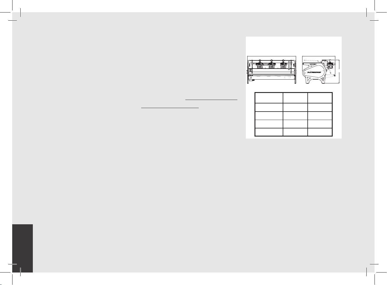
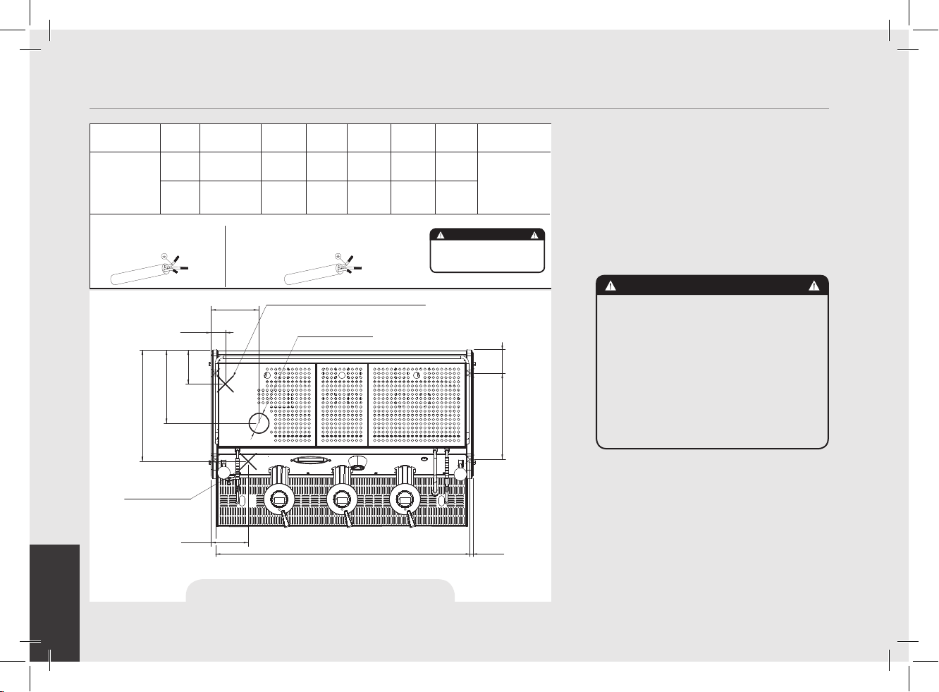
20) Common Dimensions, Weights,
and Features
A B
STRADA MP
A [mm]
B [mm]
C [mm]
WEIGHT [kg]
2 groups
800
675
475
70
3 groups
C
1000
675
475
91
6
EN
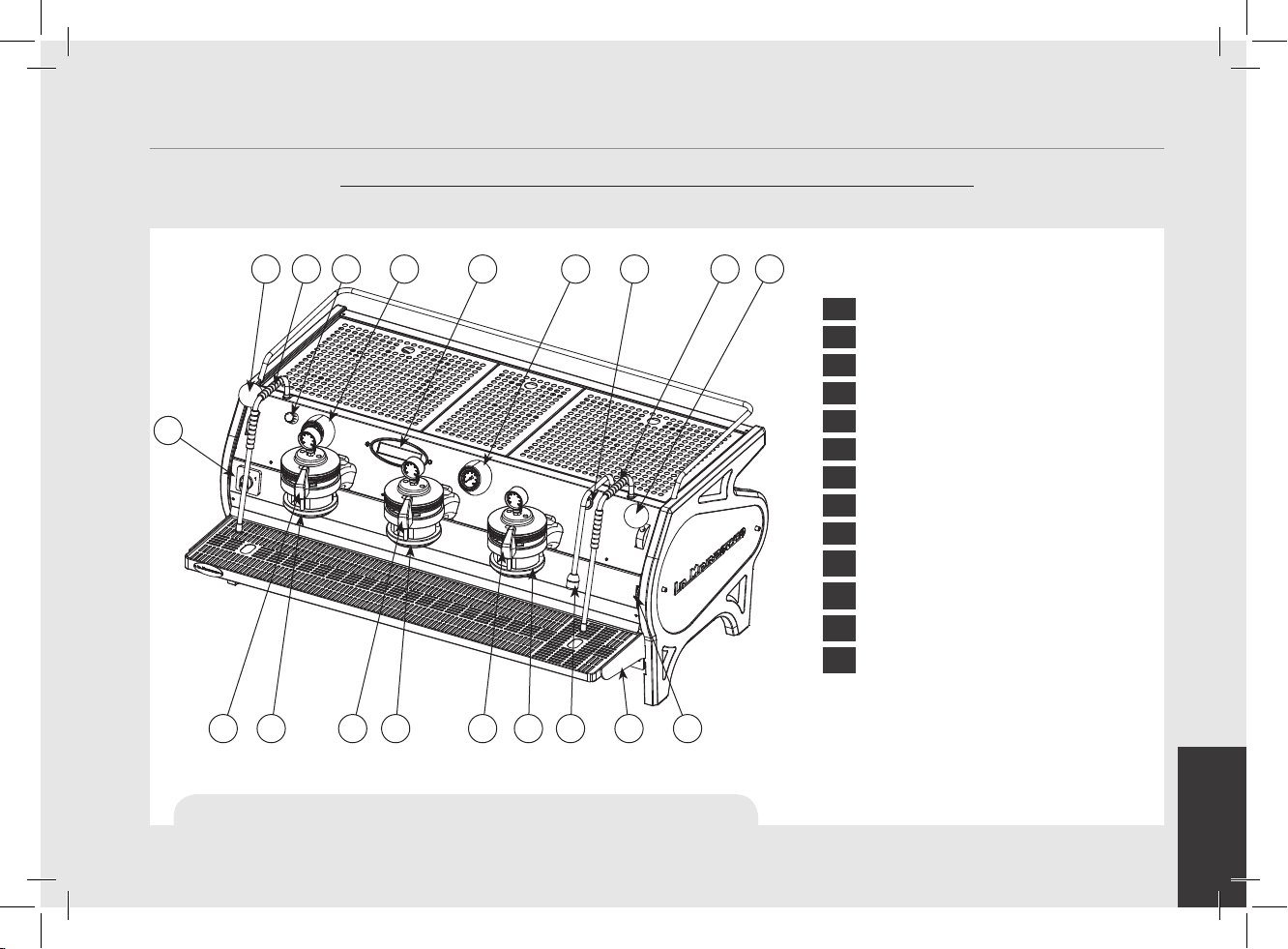
2. Denition of Available Models
This operating manual refers exclusively to the following models, of our own manufacture:
STRADA, Model MP 3 groups
2 3
5
1
444
10 11121212 13
Fig. 1 - Model MP with 2 or 3 groups
67 889 9
Legend
1 Main Switch
2 Pressure Gauge (steam boiler)
3 Pressure Gauge (coffee boiler)
4 Brew Groups
5 Encoder
6 Tea Water Button
7 Digital Display
8 Steam Wand
9 Steam Wand Lever
10 Hot Water Wand
11 Removable Drain Tray
12 Manual Brew Paddle Lever
13 Hot Water Mix Valve
For additional information on electronics,
keypads, and software programming,
please see the section entitled Software
Programming your Espresso Machine.
7

EN
1) General Description
The machine is built in 2 and 3 coffee
group versions and is essentially composed
of the following parts:
• Steam Boiler (produces steam and hot
water);
• Coffee (“saturated”) boiler;
• Brewing groups;
• Exterior Cover;
• Water pump.
2) Description of the various parts
• Steam Boiler
The Steam Boiler consists of a cylindrical
tank, of varying length according to the
number of coffee groups, which is made
of AISI 300 series stainless steel. Each
unit is subjected to a hydraulic test, at a
pressure of 6 bar, and has an operating
pressure of 1.3-1.5 bar. The following
is a list of effective volumes and power
ratings according to the number of groups
installed:
2 groups 8,2 liters 3000 Watts
3 groups 11,8 liters 4000 Watts
Covers are welded at either end of the
cylindrical tank and on one of them there
is a housing for the water heating element,
which allows the steam boiler to reach
operating pressure within approximately
25 minutes. Operating pressure is
maintained by temperature probe. The
steam boiler has various ttings used for
safety devices, for supplying hot water and
steam, and for the heating element.
Composed of AISI 300 series stainless
steel tube. Heating is accomplished
through an immersion-type plated heating
element.
• Operating pressure of 1.3-1.5 bar,
controlled automatically through a
pressure switch or a temperature
probe, adjusted to open the heating
element supply circuit at 1.5 bar and
close it at 1.3 bar.
• The pressure is displayed by means of
a pressure gauge with a scale of 0 to 2
bar.
• Safety device, based on an expansion
type mechanical valve, with counteracting spring adjusted to 1.8 bar.
• Testing: hydraulic test at 4.5 bar
performed on ready-to-use small
boilers, at our factory.
• Coffee Boiler
The Coffee Boiler consists of a cylindrical
tank made of AISI 300 series stainless
steel. One each group (hot water generator
for brewing coffee).
Each unit is subject to a hydraulic test,
at a pressure of 18 bar, and has an
operating pressure of 9 bar. The following
is a list of effective volume and power
ratings according to the number of groups
installed:
2 groups 2 x 1,3 liters 2 x 800 Watts
3 groups 3 x 1,3 liters 3 x 800 Watts
Covers are installed at either end of the
cylindrical tank and on one of them there
is housing for the water heating elements.
The temperature of the coffee boiler is
maintained by an electronic temperature
controller (PID capable) with an accuracy
of 0.2°C. The brewing groups are installed
on the boiler.
Composed of an AISI 300 series stainless
steel tube. Heating is accomplished
through an immersion-type plated heating
element.
• Operating temperature 95°C (adjustable),
controlled automatically by an electronic
temperature controller with an accuracy
of 0.2 °C. Operating pressure of 9 bar,
developed mechanically by a special
positive-displacement pump which
is activated automatically every time
coffee is brewed.
• Pressure is displayed through a pressure
gauge with a scale from 0 to 15 bar.
• Safety device, based on an expansion
type mechanical valve, with
counteracting spring adjusted to 13.5
bar.
8
EN
• Testing: Hydraulic test at 18 bar
performed on ready-to-use small boilers,
at our factory.
• Brewing groups
They consist of a precision casting made
of stainless steel. The brewing group
accepts the portalter used to hold the
ground coffee; the espresso ows through
the brewing group, through the portalter
basket, through the portalter spout, and
into the cup(s) after the brewing button
has been pressed.
• Exterior cover
The exterior consists of painted and
stainless sheet steel panels. To provide
good aesthetics, to optimize ergonometrics
for the operator and to reduce the chance
of damage to a minimum.
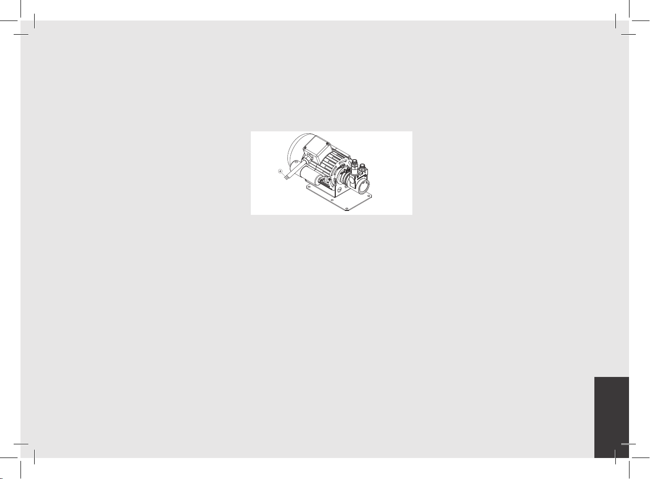
• Water pump
The rotary vane pump, is installed on the
water supply tubing and is set up to operate
anytime the coffee groups are activated,
and through an autoll system whenever
the water boiler needs to be replenished.
9
EN
3. Installation
LA FIGURA AFFIANCO DESCRIVE COME
COLLEGARE OGNI FILO ALLA SPINA.
RISPETTARE ANCHE LE NORME FEDERALI,
STATALI O LOCALI VIGENTI.
MODELLO/SERIE GRUPPO V/Hz
POTENZA
NOMINALE
(W)
INPUT
NOMINALE
(A)
POTENZA
CALDAIA
CAFFE’
POTENZA
CALDAIA
VAPORE
POTENZA
TOTALE
DIMENSIONE CAVO
ALIMENTAZIONE
ELETTRICA (mm²)
STRADA MP
2GR
A
C220-240V/60H
z
AC208-240/60Hz
AC380/50Hz
4600
20-22
1600 3000 4600
12
PER DETTAGLI
3GR 6400
2400 4000 6400
VEDERE I
COLLEGAMENTI
ELETTRICI
ATTENZIONE
AC220-240V/60Hz
AC208-240/60Hz
AC380/50Hz
23
25-29
16
30,5
RATED
(W)
RATED
(A)
COFFEE
WATTAGE
STEAM
WATTAGE
POWER CORD
A
z
1 X BLU (NEUTRO)
1 X MARRONE (FASE)
1 X GIALLO & VERDE (TERRA)
CAVO ALIMENTAZIONE ELETTRICA:
5 X FILI
380V
1 X MARRONE (FASE)
1 X GRIGIO (FASE)
1 X NERO (FASE)
1 X BLU (NEUTRO)
1 X GIALLO & VERDE (TERRA)
3 X FILI
220V
HERE THE POSITION OF THE POWER CORD AND
13 in.
POSITION OF THE HIGH LEGS MACHINE
MODEL/SERIES GROUP V/Hz
STRADA MP
1 X BLUE (NEUTRAL)
3 X WIRES
220V
1 X BROWN (PHASE)
1 X YELLOW & GREEN (GROUND)
HERE THE POSITION
OF THE DRAIN TUBE
POWER
C220-240V/60H
2GR
AC208-240/60Hz
AC380/50Hz
AC220-240V/60Hz
3GR 6400
AC208-240/60Hz
AC380/50Hz
POWER CORD:
5 X WIRES
1 X BROWN (PHASE)
380V
1 X GRAY (PHASE)
1 X BLACK (PHASE)
210 mm
4 in.
55 mm
2,1 in.
5,1 in.
130 mm
11 in.
280 mm
16,7 in.
425 mm
140 mm
5,5 in.
INPUT
BOILER
20-22
4600
23
12
25-29
30,5
16
1 X BLUE (NEUTRAL)
1 X YELLOW & GREEN (GROUND)
FROM ∅80 TO ∅100 mm
FROM ∅3 in. TO ∅4 in.
WATER INLET HOSES
1600 3000 4600
2400 4000
775 mm (2 groups)
30,5 in. (2 groups)
975 mm (3 groups)
38 in. (3 groups)
BOILER
TOTAL
WATTAGE
6400
WARNING
THE DETAILS ON THE LEFT DESCRIBE
HOW TO CONNECT EACH WIRE TO THE PLUG.
RESPECT ALSO THE LOCAL SAFETY
HERE THE POSITION WHERE WE
SUGGEST TO MAKE THE HOLE
ON THE TABLE
SIZE (mm²)
SEE ELECTRICAL
CONNECTIONS
FOR DETAILS
REGULATIONS.
94 mm
328 mm
12,5 mm
0,5 in.
3,7 in.
WARNING
The machine is intended to be
permanently connected to xed
wiring, and it is mandatory that
a residual current device (RCD)
with a rated residual operating
current not exceeding 30mA is
installed.
Fig. 2 - Installation guide
10
EN
WARNING
The Coffee Boiler and Steam
Boiler contain water at elevated
temperature. Water temperature
over 125°F / 52°C can cause
severe burns instantly or death
from scalding (Coffee Boiler
207°F/97°C - Steam Boiler
256°F / 124°C)
WARNING
At each installation, the machine
should be equipped with a new
set of tubes for plumbing and
related gaskets.
WARNING
Water pressure supply must be
between 2 and 6 bar if sufcient
pressure is not available we
suggest that an additional water
supply system is used.
WARNING
Hazardous voltage disconnect
from power supply before
servicing.
WARNING
Before making any electrical
connections make sure that the
two strain relief connectors are
rmly secured to the body of
the machine in order to prevent
inadvertent stress on the power
cables.
WARNING
The motor pump must be
situated close to the machine
in an accessible place for
maintenance but not for
accidental interference and
where there is an optimal air
circulation.
WARNING
Replace fuses with the same
size, type and rating F1 = 2A,
250V
WARNING
- U.S.A. and CANDA only - Do not
connect to a circuit operating
at more than 150V to ground on
each leg.
WARNING
The manufacturer declines
any responsibility for any
event leading to liability suits
whenever grounding has not
been completed according to
current local, national, and
international regulations and
electrical codes, or other
electrical parts have been
connected improperly.
11
EN
WARNING
This machine should not be
installed in kitchens.
WARNING
This appliance is not intended
for use by persons (including
children) with reduced physical,
sensory or mental capabilities,
or with lack of experience and
knowledge, unless they have
been given supervision or
instruction concerning the use
of the appliance by a person
responsible for their safety.
WARNING
This machine is not suitable for
outdoor use. Jets of water should
not be used to clean the machine,
nor should it be placed where
water jets are used.
WARNING
In order to prevent cracks
or leakage: do not store or
install the Coffee machine
in places where in boiler or
hydraulicsystem to freeze.
Note:
• The drinking water mains valve and
the circuit breakers for the electrical
system need to be located in the most
convenient position for the operator to
access them easily and quickly.
• The machine should be placed on a at
counter and must be placed in settings
with the following temperatures:
Minimum room temperature: 5°C/41°F
Maximum room temperature:
32°C/89°F
• If the machine has been temporarily
housed in settings with a room
temperature of less 0°C/32°F, the
machine must be placed in a warmer
environment in order to gradually
defrost the hydraulic system prior to
use.
• Water pressure supply must be between
2 and 6 bar.
• This machine complies with the
standard 61000-3-11, the impedance
at the supply interface must be Zmax=
0.11 Ω.
12
EN
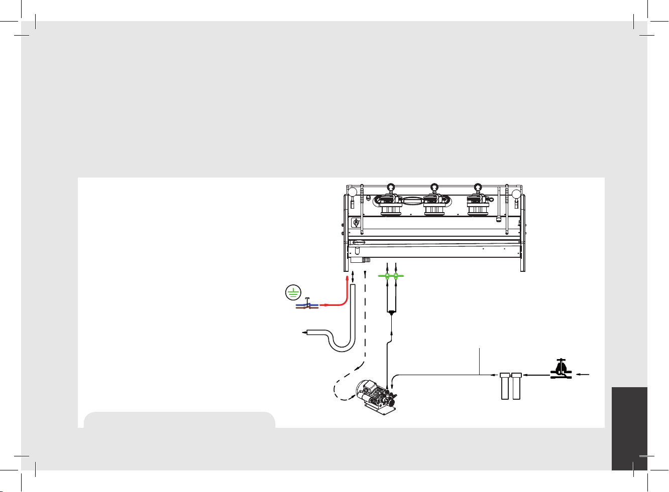
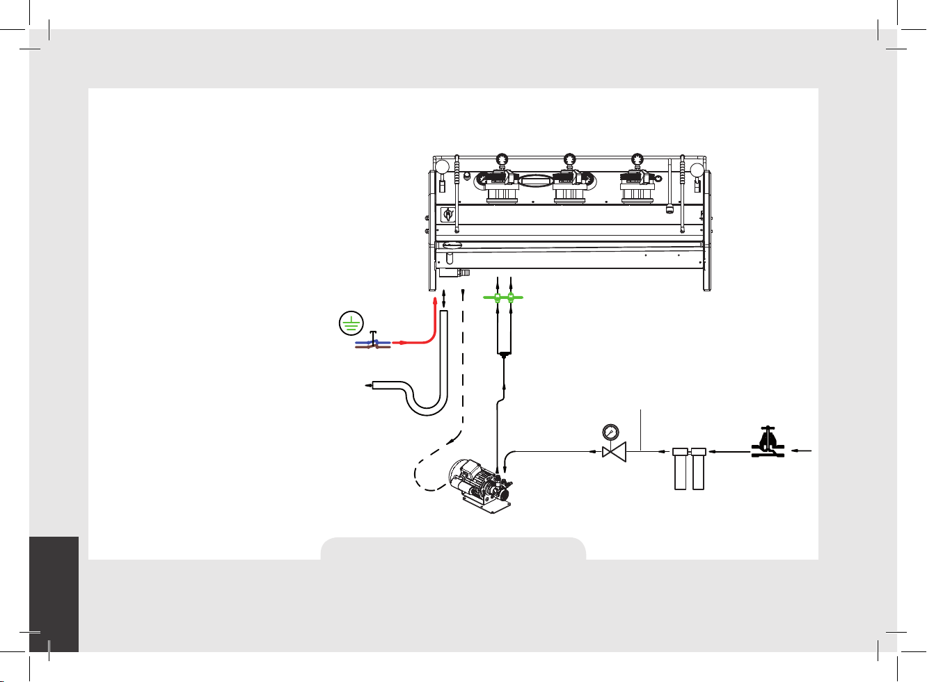
1) Installation guide
TEE FITTINGS
ROTARY PUMP
PRESSURE REDUCER
PRESSURE ≤ 9 BAR
WASTE/DRAIN
MAIN SWITCH
AND ELECTRICAL SUPPLY CONNECTION
POWER SUPPLY
CORD
COFFEE
BOILER
STEAM
BOILER
BRAIDED HOSE
For best results, STRADA needs a minimum ow of water in input of 100 l/h and a pressure of 2.5 bar.
Installations that do not meet these requirements will cause a shorter life of the pump and may cause a high noise level during coffee brewing.
If the pressure and ow are not adequate, air bubbles may develop within the gears. This is called cavitation. Cavitation can impair the
performance of the espresso machine.
If the incoming water of the espresso machine falls outside the recommended parameters, it is necessary to carry out one of the following
installations:
Pressure lower than 9 bar
Flow rate lower than 100 l/h
Installation with the rotary pump
immediately after the water treatment
system, upstream of the tee.
POWER SUPPLY
Fig. 3 - Installation guide - type 1
CORD
MAIN SWITCH
AND ELECTRICAL SUPPLY CONNECTION
WASTE/DRAIN
ROTARY PUMP
STEAM
BOILER
COFFEE
BOILER
TEE FITTINGS
BRAIDED HOSE
WATER CHECK POINT:
FLOW RATE < 100 l/h
PRESSURE ≤ 9 BAR
WATER TREATMENT
RECOMMENDED VALUES
www.lamarzocco.com/water_calculator
MAIN WATER
SUPPLY VALVE
13
EN
Pressure higher than 9 bar
Flow rate lower than 100 l/h
Installation of the pressure reducer
immediately after the water treatment
system, upstream of the rotary pump.
Installation of the rotary pump (set to 9
bar) immediately after the pressure reducer,
upstream of the tee.
14
POWER SUPPLY
CORD
MAIN SWITCH
AND ELECTRICAL SUPPLY CONNECTION
WASTE/DRAIN
ROTARY PUMP
Fig. 4 - Installation guide - type 2
STEAM
BOILER
COFFEE
BOILER
TEE FITTINGS
BRAIDED HOSE
WATER CHECK POINT:
FLOW RATE < 100 l/h
PRESSURE > 9 BAR
PRESSURE REDUCER
PRESSURE ≤ 9 BAR
WATER TREATMENT
RECOMMENDED VALUES
www.lamarzocco.com/water_calculator
MAIN WATER
SUPPLY VALVE
EN
2) Accessories
Check the package to make sure that the
following accessories are included:
• a number of 1-dose and 2-dose
portalters orresponding to the number
of groups;
• replacement 1-dose and 2-dose lters
(one of each);
• 1 tamper;
• 1 blind lter;
• cleaning detergent, for the groups;
• 3 stainless steel braided hoses for
water connections;
• 1,5 mt of reinforced plastic tubing for
drainage;
• 1 hose clamp;
• 1 TEE Fitting.
In order to proceed with installation, it is
necessary that the following are available:
• Pipes carrying drinking water with a
3/8”G (BSP) end connection; (3/8”
Compression for USA and Canada)
• Electrical Supply according to the
specication of the espresso machine
purchased:
• Single/Three phase 220VAC - 50/60
Hz electrical connection with ground,
protected socket and approved
interlock switch
• Single phase 200VAC - 50/60 Hz
electrical connection with ground,
protected socket and approved
interlock switch
• Three-phase, 380VAC - 50 Hz
electrical connection with neutral +
ground, near the bench on which the
machine is installed and terminating
in a suitable protected vepole socket
equipped with an approved interlock
switch
• Waste water drain system.
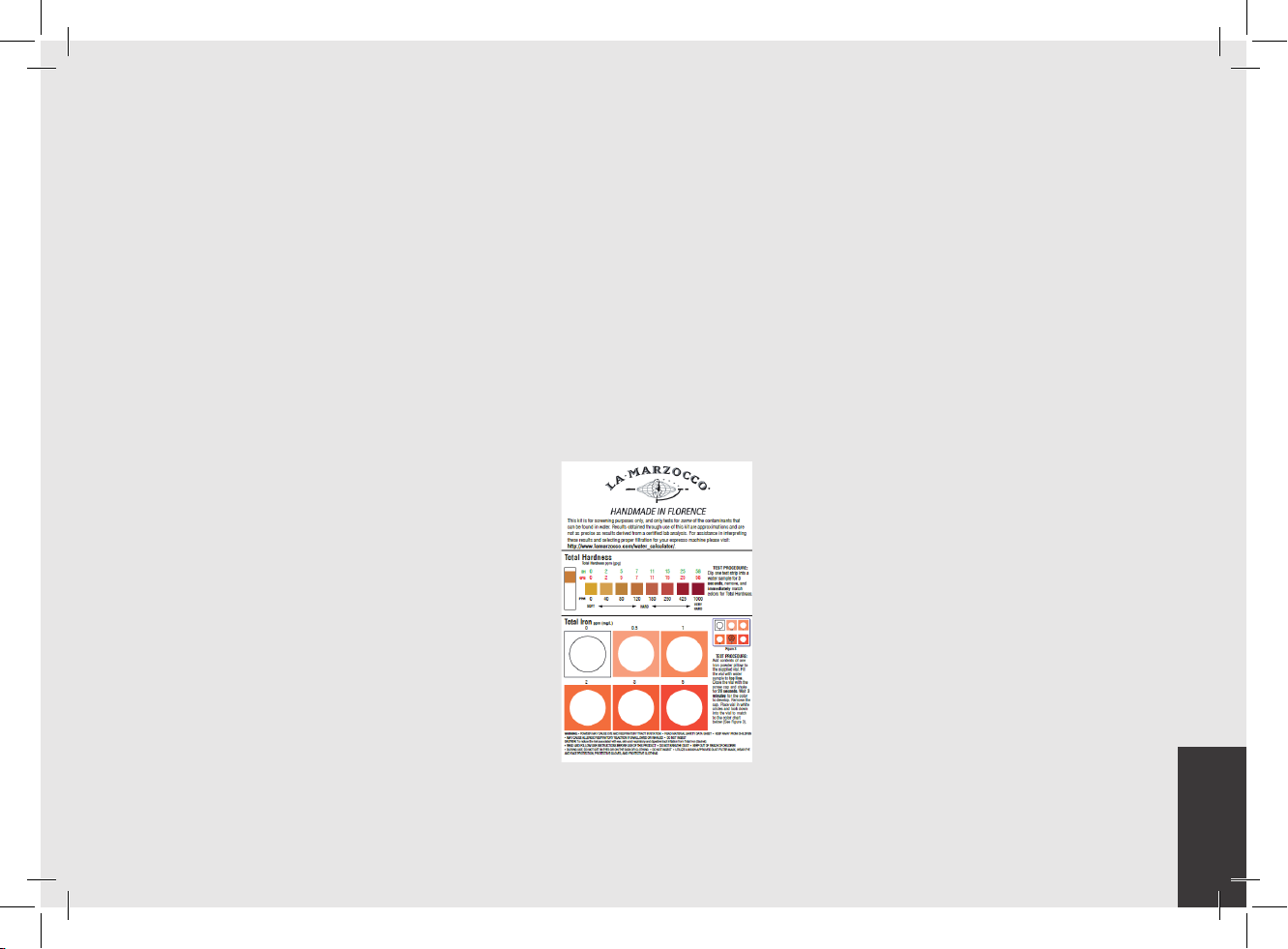
3) Water test kit
In order to enable you to check if your water
supply is within the suggested ranges, La
Marzocco machines will be equipped with
two units of a quick water test kit (see image
below) including 6 test-strips and instruction
cards.
The parameters that you can measure are
Total Hardness, Total Iron, Free Chlorine,
Total Chlorine, pH & Total Alkalinity,
Chlorides.
Ideally, you should perform a test on the
water BEFORE the water treatment system
and again AFTER the water system in order
to verify if this is actually matching our
suggested ranges.
Once the test has been performed, learn
which treatment system is most appropriate
for your particular water supply by lling out
the online water calculator on our website: LA
MARZOCCO WATER CALCULATOR (http://
www.lamarzocco.com/water_calculator/).
4) Water supply connection
In order to connect the machine up to
the water mains proceed according to the
indications given in the chapter about
Installation and in compliance with any
local/national safety standards of the
location in which the machine is being
installed.
To guarantee a correct and safe functioning
of the machine and to maintain an
adequate performance level and a high
quality of the beverages being brewed it
is important that the incoming water be
of a hardness greater than 7°f (70ppm,
4°d) and less than 10°f (100ppm, 6°d),
pH should be between 6.5 and 8.5 and
the quantity of chlorides be less than
50mg/l . Respecting these values allows
the machine to operate at maximum
15
EN
efciency. If these parameters are not
present, a specic ltration device should
be installed, while always adhering to the
local national standards in place regarding
potable water.
Then connect the inlet of the water lter/
softener (if present) to the drinking water
supply using one of the supplied stainless
steel braided hoses. Before connecting
the lter to the water pump, ush the
water supply line and the ltration system
in order to eliminate any residual particles
which could otherwise get stuck in taps or
valves thus preventing them from working
properly. Connect the water supply
connection of the espresso machine to
the water pump outlet using one of the
supplied stainless steel braided hoses.
Then connect the water pump inlet to the
water lter/softener outlet (if present).
5) Electrical connections
a) Power supply cord
• This is the main power supply cable
that provides power to the entire espresso
machine. There are different types of cable
based upon the electrical requirements of
the espresso machine purchased:
• 200/220VAC 1 Phase 3-core cable
with 4/6/10mm2 cross section or AWG
12/10/8 for 2,3 4 group versions, secured
to espresso machine via a strain relief
connector
• 220VAC 3 Phase 4-core cable with 4
mm2 cross section for 2 , 3 and 4 group
versions, secured to espresso machine via
a strain relief connector
• 380 VAC 3 Phase 5-core cable with
2.5mm2 cross section for 2, 3 and 4 group
versions, secured to espresso machine via
a strain relief connector.
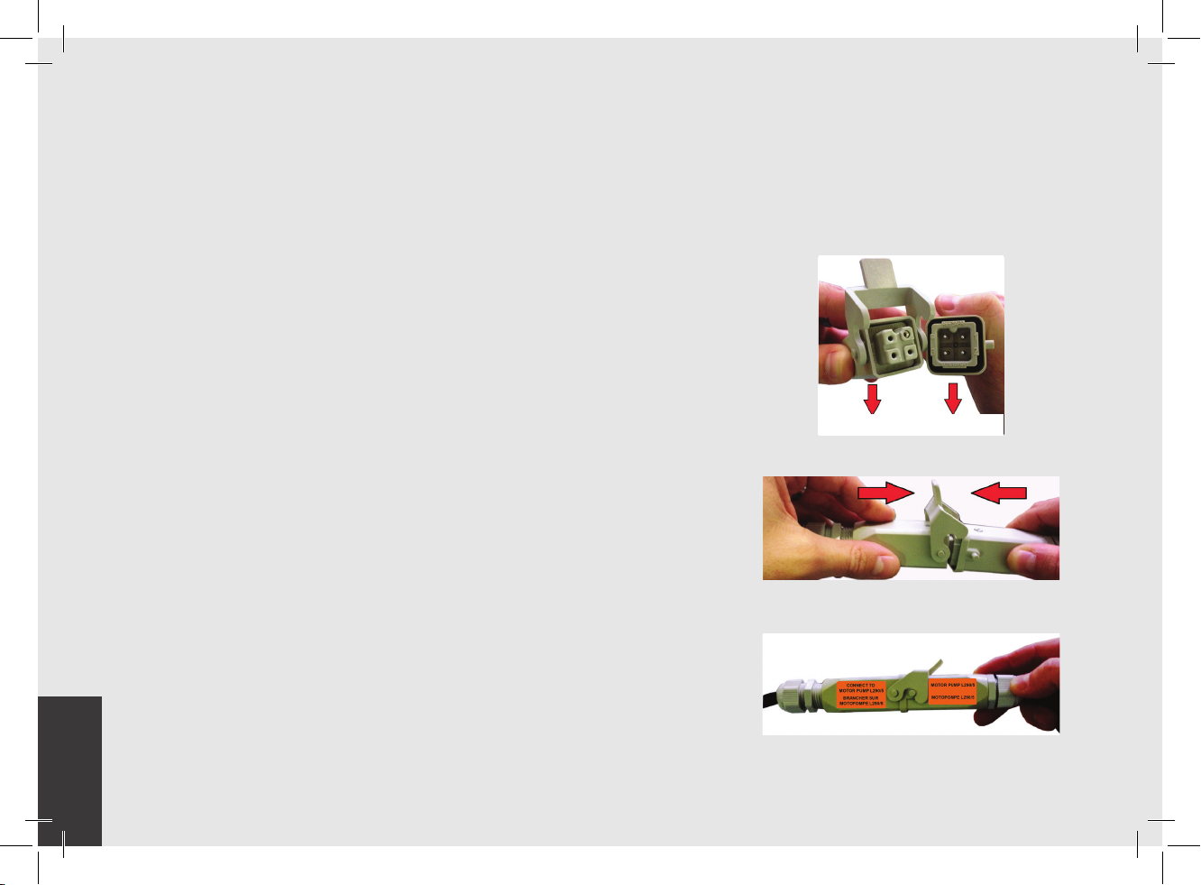
c) Quick connection between the water pump and
the espresso coffee machine
The electrical connection must be made
through the use of the connectors, as
shown in the following gures:
- View of the connectors;
Machine connector Pump connector
- Cable connection;
Note: The water pump is a differential
pressure volumetric pump and has been
designed to be used exclusively with cold
water. Make sure that water is always
present while the pump is operating,
otherwise air can be introduced into the
brew boiler causing an undesireable
condition and the pump can be damaged.
16
b) Water pump motor power cord
This is the power supply for the water
pump motor. The internal electronics will
switch the pump motor on when needed.
• 3-core cable with 1.5 mm2 cross section
or 3-core AWG 16 (for UL version) secured
to espresso machine via a strain relief
connector.
- Cable tightening;
EN
6) Waste water drain connection
The espresso machine drain is to be
connected by means of the included
reinforced plastic tubing. Connect one end
of the reinforced plastic tubing to the drain
hose connection on the left side of the
espresso machine, secure with included
hose clamp. Connect the other end to a
suitable waste water collection system.
In case such a system is not available,
drained liquids may be collected in a
suitable bucket and any necessary drain
pipe extensions shall be made using
steel-lined PVC tubing and suitable hose
clamps.
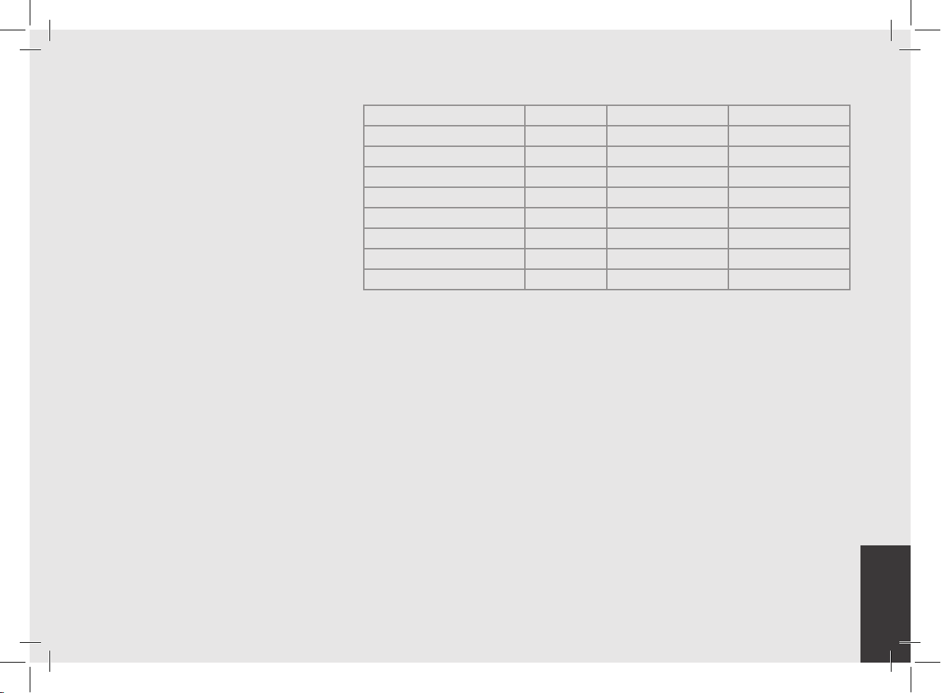
Water specications table
Min. Max.
T.D.S. ppm 90 150
Total Hardness ppm 70 100
+2
Total Iron (Fe
Free Chlorine (Cl
Total Chlorine (Cl
pH value 6,5 8,5
Alkalinity ppm 40 80
Chloride (Cl
N.B.: Test water quality (the warranty is void if water parameters are not within the range
specied in the section “installation”)
/Fe+3) ppm 0 0,02
) ppm 0 0,05
2
) ppm 0 0,1
2
–
) ppm not more 50
17

EN
4. Machine Operation and Coffee Preparation
CAUTION
Never remove the lter holder
when water is being delivered.
This operation can be extremely
dangerous since the high
pressure built-up inside the
blind lter would spray out hot
and slightly caustic water, which
may cause severe burns. The
Coffee Boiler contains water at
elevated temperature. Water
temperature over 125°F / 52°C
can cause severe burns instantly
or death from scalding.
WARNING
The machine must not be dipped
in, nor splashed with, water in
order to clean it. For cleaning
operations, please follow the
instructions listed below very
carefully.
18
This machine is designed only
for preparing coffee and hot
IMPORTANT
To improve the avor of the espresso, the
temperature of the water in the coffee boiler
and therefore of the groups may eventually
be raised or lowered via the digital display
(please consult the Software Programming
Manual for detailed instructions).
1) Starting the Espresso Machine
Filling the Boilers with Water:
Once the installation procedures have been
completed, it is necessary to ll the boiler
tanks with water. Complete the following
procedure to properly ll the boiler tanks:
• Coffee Boiler
The water ows inside the coffee boilers
directly, as soon as the water system and
water lter/softener valves are opened.
Since the inow of water will compress
the air in the boiler, it will be necessary to
remove or “bleed” the air from the coffee
boilers. All air must be removed in order
to completely “saturate” the coffee boiler/
group assemblies.
To remove the air from the boiler, or “bleed
WARNING
drinks.
the groups”, it will be necessary to remove
the plastic cap and the handle from the
top of the group.
Loosen the bleed screws one at a time
to allow air to escape until water ows
from below the screw head. Tighten the
screw to stop the water from owing. Over
tightening can cause damage to the sealing
washer and the group cover. Repeat this
procedure on all groups.
• Steam Boiler
Turn the main switch to position “1” or
ON, then push the encoder knob for
three seconds and the automatic steam
boiler level function will be switched on,
activating the auto-ll solenoid valve and
the motor pump. This will ll the steam
boiler to a predetermined level and will
shut off when full.
 Loading...