

Page 1

manual
strada av
The Strada AV is characterized by its underlying mechanical features
and design of the Strada. The initials “AV” refer to a feature whereby
brewing is activated by a three button keypad where the doses
are counted by a owmeter for each group. This model includes
proportional steam valves, both featuring anti-resuction valves.
Page 2

strada av
Operating Manual V2.0 - 12/2016
MAN.16.1.02
EN
certications available:
La Marzocco S.r.l.
Via La Torre 14/H
Località La Torre
50038 Scarperia e San Piero
(Firenze) - ITALIA
www.lamarzocco.com
info@lamarzocco.com
T: +39 055 849 191
F: +39 055 849 1990
Chapters
1. General Warnings and Safety Specications
2. Denition of Available Models
3. Installation
4. Machine Operation and Coffee Preparation
5. Dispensing Steam and Hot Water
6. Maintenance and Periodic Cleaning Operations
7. De-commissioning and Demolition
8. Mandatory Maintenance and Check-up Operations
9. Precision Scale
10. Software Programming Guide
page 3
page 7
page 10
page 17
page 20
page 21
page 23
page 24
page 25
page 28
Page 3
EN
1. General Warnings and Safety Specications
WARNING
This machine is for professional
use only and should be installed
in locations where its use and
maintenance is restriced to
trained personnel. Children are
forbidden to operate or play with
the machine.
WARNING
The Coffee machine must be
placed in a horizontal position on
a counter higher than 80 cm from
the ground.
WARNING
This machine is not suitable
for outdoor use. Jets of water
should not be used to clean the
machine, nor should it be placed
where water jets are used.
CAUTION
As already mentioned in
the preceding notes, the
manufacturer shall not be held
responsible for damage to
objects, animals and/or people
whenever the machine has not
been installed according to the
instructions contained in this
manual, and is not used to do
what it was designed for (i.e.
preparing coffee and hot drinks).
1) Important safeguards
• The weighted sound
pressure level of the
machine is lower than
70dBA.
• Use, cleaning and
maintenance of this coffee
machine are realized
by people (including
children more than 8
• Children should be
• Keep the appliance and
2) This operating manual
is an integral and essential
part of the product and
years of age) with reduced
physical, sensory or mental
capabilities, or lack of
experience and knowledge,
as long as they have
been given supervision or
instructions concerning
the use of the appliance
by a person responsible
for their safety and if they
understand dangers.
supervised to ensure that
they do not play with the
appliance.
its cord out of the reach of
children less than 8 years
of age.
3
Page 4

EN
must be supplied to users.
Users are asked to read
the enclosed warnings and
cautions carefully, as they
provide valuable information
concerning safety during
installation, operation and
maintenance. This manual
must be kept in a safe
place and be available for
consultation to new and
experienced users alike.
3) Ensure product’s integrity
by inspecting the packaging,
making sure it presents no
signs of damage which might
have affected the enclosed
machine.
4) Check the machine’s
integrity after having carefully
removed the packaging.
Note: In case of doubt, do not go
on any further and contact your
dealer or retailer immediately. They
will send out specialized personnel
authorized to perform service on
the espresso machine.
5) Packaging (boxes, plastic
bags, foam parts and whatever
else) must not be left around
within easy reach of children,
due to the potential danger it
represents, nor be discarded
in the environment.
6) Check to see that data on
the rating plate corresponds
to those of the main electrical
supply which the machine will
be hooked up to.
7) The equipment must be
installed to comply with the
applicable federal, state or
local electrical and plumbing
codes. The installation
also must comply to the
manufacturer’s instructions,
and must be performed by
qualied and authorized
personnel.
8) Incorrect installation may
cause for injury/damages to
people, animals or objects, for
which the manufacturer shall
not be held responsible.
9) Safe electrical operation of
this device will be achieved
only when the connection to
the power outlet has been
completed correctly and
in observance of all local,
national, and international
electrical codes and safety
regulations, and particularly
by grounding the unit.
Make sure grounding has
4
Page 5
EN
been done properly as it
represents a fundamental
safety requirement. Ensure
qualied personnel check
such connection.
10) Furthermore, you must
ensure that the capacity of
the available electrical system
is suitable for the maximum
power consumption indicated
on the espresso machine.
11) We do not recommend
using adapters, multiple
plugs and/or extension cords.
If you cannot avoid using
them, make sure that they are
exclusively of the kind which
conforms to local, national,
and international electrical
codes and safety regulations,
being careful not to exceed
the power and current ratings
indicated on such adapters
and extension cords.
12) This device must be used
exclusively for the functions it
has been designed and built
for. Any other application is
inappropriate and dangerous.
The manufacturer shall not be held
responsible for any damages caused
by improper and/or irrational use.
This machine should not be
installed in kitchens.
13) Using any electrical
device requires that certain
fundamental rules be
observed. In particular:
• do not touch the device
with wet or humid hands
and feet;
• do not use the device while
having no shoes on your
feet;
• do not use extension cords
in bath or shower rooms;
• do not unplug the device
from the power outlet by
pulling on the power supply
cable;
• do not expose the device to
atmospheric agents (rain,
sun, etc.);
• do not allow children or
untrained people to use
this device;
• do not clean the control
panel with a wet cloth since
it is not watertight.
14) Before carrying out any
maintenance and/or cleaning
operations, turn the main
switch, which is located on
the front left of the machine,
to the “0” or “OFF” position,
and disconnect the machine
from the electrical network
5
Page 6

EN
by unplugging the cord or
by switching off the relative
circuit breaker. For any
cleaning operation, follow
exclusively the instructions
contained in this manual.
15) In case the machine is
operating in a faulty manner
or breaks down, disconnect
it from the electrical network
(as described in the preceding
point) and close the water
supply valve. Do not attempt
to repair it. Contact a qualied
and authorized professional to
perform any repair. Any repairs
must be performed exclusively
by the manufacturer or by
an authorized centre using
only original parts. Non
compliance with the above
could compromise the safe
operation of the machine.
6
16) You should plan to
make use of an omnipolar
connector during installation,
as required by local, national,
and international electrical
codes and regulations.
17) In order to avoid dangerous
overheating problems, it is
recommended that the power
supply cable be fully unfurled.
18) Do not obstruct air intake
and exhaust grilles and, in
particular, do not cover the
cup warmer tray with cloths or
other items.
19) The machine’s power
supply cable must not be
replaced by users. In case the
power supply cable becomes
damaged, shut off the
machine and disconnect the
machine from the electctrical
network by switching off the
relative circuit breaker and
close off the water supply;
to replace the power supply
cord, contact qualied
professionals exclusively.
20) Common Dimensions, Weights,
and Features
A
STRADA AV 2 groups
A [mm]
B [mm]
C [mm]
WEIGHT [kg]
800
675
475
70
B
3 groups
1000
675
475
91
C
Page 7

EN
2. Denition of Available Models
This operating manual refers exclusively to the following models, of our own manufacture:
STRADA, model AV 3 groups
9
1
2 3
5 67 88
444
Fig. 1 - Model AV with 2 or 3 groups
910
1112 13
Legend
1 Main Switch
2 Pressure Gauge (steam boiler)
3 Pressure Gauge (coffee boiler)
4 Brew Groups
5 Cup Warmer Button
6 Tea Water Button
7 Digital Display
8 Steam Wand
9 Steam Wand Lever
10 Hot Water Wand
11 Removable Drain Tray
12 Group #1 Programming Keypad
13 Hot Water Mix Valve
For additional information on electronics,
keypads, and software programming,
please see the section entitled Software
Programming your Espresso Machine.
7
Page 8

EN
1) General Description
The machine is built in 2 and 3 coffee
group versions and is essentially composed
of the following parts:
• Steam Boiler (produces steam and hot
water);
• Coffee (“saturated”) boiler;
• Brewing groups;
• Exterior Cover;
• Water pump.
2) Description of the various parts
• Steam Boiler
The Steam Boiler consists of a cylindrical
tank, of varying length according to the
number of coffee groups, which is made
of AISI 300 series stainless steel. Each
unit is subjected to a hydraulic test, at a
pressure of 6 bar, and has an operating
pressure of 1.3-1.5 bar. The following
is a list of effective volumes and power
ratings according to the number of groups
installed:
2 groups 8,2 liters 3000 Watts
3 groups 11,8 liters 4000 Watts
Covers are welded at either end of the
cylindrical tank and on one of them there
is a housing for the water heating element,
which allows the steam boiler to reach
operating pressure within approximately 25
minutes. Operating pressure is maintained
by temperature probe and PID controller.
The steam boiler has various ttings used
for safety devices, for supplying hot water
and steam, and for the heating element.
Composed of AISI 300 series stainless
steel tube. Heating is accomplished
through an immersion-type plated heating
element.
• Operating pressure of 1.3-1.5 bar,
controlled automatically through a
pressure switch or a temperature
probe, adjusted to open the heating
element supply circuit at 1.5 bar and
close it at 1.3 bar.
• The pressure is displayed by means of
a pressure gauge with a scale of 0 to 2
bar.
• Safety device, based on an expansion
type mechanical valve, with counteracting spring adjusted to 1.8 bar.
• Testing: hydraulic test at 4.5 bar
performed on ready-to-use small
boilers, at our factory.
• Coffee Boiler
The Coffee Boiler consists of a cylindrical
tank made of AISI 300 series stainless
steel. One each group (hot water generator
for brewing coffee).
Each unit is subject to a hydraulic test,
at a pressure of 18 bar, and has an
operating pressure of 9 bar. The following
is a list of effective volume and power
ratings according to the number of groups
installed:
2 groups 2 x 1,3 liters 2 x 800 Watts
3 groups 3 x 1,3 liters 3 x 800 Watts
Covers are installed at either end of the
cylindrical tank and on one of them there
is housing for the water heating elements.
The temperature of the coffee boiler is
maintained by an electronic temperature
controller (PID capable) with an accuracy
of 0.2°C. The brewing groups are installed
on the boiler.
Composed of an AISI 300 series stainless
steel tube. Heating is accomplished
through an immersion-type plated heating
element.
• Operating temperature 95°C
(adjustable), controlled automatically
by an electronic temperature controller
with an accuracy of 0.2 °C. Operating
pressure of 9 bar.
• Pressure is displayed through a pressure
gauge with a scale from 0 to 18 bar.
• Safety device, based on an expansion
type mechanical valve, with
ounteracting spring adjusted to 13 bar.
• Testing: Hydraulic test at 18 bar
performed on ready-to-use small boilers,
at our factory.
8
Page 9
EN
• Brewing groups
They consist of a precision casting made
of stainless steel. The brewing group
accepts the portalter used to hold the
ground coffee; the espresso ows through
the brewing group, through the portalter
basket, through the portalter spout, and
into the cup(s) after the brewing button
has been pressed.
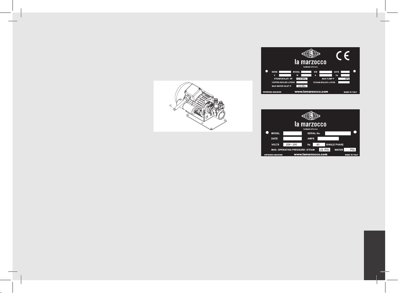
• Water pump
The rotary vane pump, is installed on the
water supply tubing and is set up to operate
anytime the coffee groups are activated,
and through an autoll system whenever
the water boiler needs to be replenished.
• Machine CE plate:
STRADA 3AV ST000000 01/16
220-240 7324 32 50/60
1.3x3
0.9
11.8
• Exterior cover
The exterior consists of painted and
stainless sheet steel panels. To provide
good aesthetics, to optimize ergonometrics
for the operator and to reduce the chance
of damage to a minimum.
• Machine ETL plate:
STRADA 3AV
01/16 29-33
ST000000
161
9
Page 10

EN
3. Installation
LA FIGURA AFFIANCO DESCRIVE COME
COLLEGARE OGNI FILO ALLA SPINA.
RISPETTARE ANCHE LE NORME FEDERALI,
STATALI O LOCALI VIGENTI.
MODELLO/SERIE GRUPPO V/Hz
POTENZA
NOMINALE
(W)
INPUT
NOMINALE
(A)
POTENZA
CALDAIA
CAFFE’
POTENZA
CALDAIA
VAPORE
POTENZA
TOTALE
DIMENSIONE CAVO
ALIMENTAZIONE
ELETTRICA (mm²)
STRADA AV
2GR
A
C220-240V/60H
z
AC208-240/60Hz
AC380/50Hz
4600
20-22
1600 3000 4600
12
PER DETTAGLI
3GR 6400
2400 4000 6400
VEDERE I
COLLEGAMENTI
ELETTRICI
ATTENZIONE
AC220-240V/60Hz
AC208-240/60Hz
AC380/50Hz
23
25-29
16
30,5
RATED
(W)
RATED
(A)
COFFEE
WATTAGE
STEAM
WATTAGE
POWER CORD
A
z
1 X BLU (NEUTRO)
1 X MARRONE (FASE)
1 X GIALLO & VERDE (TERRA)
CAVO ALIMENTAZIONE ELETTRICA:
5 X FILI
380V
1 X MARRONE (FASE)
1 X GRIGIO (FASE)
1 X NERO (FASE)
1 X BLU (NEUTRO)
1 X GIALLO & VERDE (TERRA)
3 X FILI
220V
140 mm
5,5 in.
12,5 mm
0,5 in.
POSITION OF THE HIGH LEGS MACHINE
775 mm (2 groups)
30,5 in. (2 groups)
975 mm (3 groups)
38 in. (3 groups)
55 mm
2,1 in.
130 mm
5,1 in.
280 mm
11 in.
425 mm
16,7 in.
HERE THE POSITION
OF THE DRAIN TUBE
HERE THE POSITION OF THE POWER CORD AND
WATER INLET HOSES
210 mm
4 in.
FROM ∅80 TO ∅100 mm
FROM ∅3 in. TO ∅4 in.
HERE THE POSITION WHERE WE
SUGGEST TO MAKE THE HOLE
ON THE TABLE
94 mm
3,7 in.
328 mm
13 in.
MODEL/SERIES GROUP V/Hz
STRADA AV
3 X WIRES
220V
10
C220-240V/60H
2GR
AC208-240/60Hz
AC380/50Hz
AC220-240V/60Hz
3GR 6400
AC208-240/60Hz
AC380/50Hz
POWER CORD:
5 X WIRES
380V
1 X BLUE (NEUTRAL)
1 X BROWN (PHASE)
1 X YELLOW & GREEN (GROUND)
POWER
1 X BROWN (PHASE)
1 X GRAY (PHASE)
1 X BLACK (PHASE)
INPUT
20-22
4600
23
12
25-29
30,5
16
1 X BLUE (NEUTRAL)
1 X YELLOW & GREEN (GROUND)
Fig. 2 - Installation guide
BOILER
BOILER
WATTAGE
1600 3000 4600
2400 4000 6400
HOW TO CONNECT EACH WIRE TO THE PLUG.
TOTAL
SIZE (mm²)
SEE ELECTRICAL
CONNECTIONS
FOR DETAILS
WARNING
THE DETAILS ON THE LEFT DESCRIBE
RESPECT ALSO THE LOCAL SAFETY
REGULATIONS.
WARNING
The machine is intended to be
permanently connected to xed
wiring, and it is mandatory that
a residual current device (RCD)
with a rated residual operating
current not exceeding 30mA is
installed.
WARNING
The Coffee Boiler and Steam
Boiler contain water at
elevated temperature. Water
temperature over 125°F /
52°C can cause severe burns
instantly or death from scalding
(Coffee Boiler 207°F/97°C -
Steam Boiler 256°F / 124°C)
WARNING
Replace fuses with the same
size, type and rating F1 = 2A,
250V
Page 11

EN
WARNING
At each installation, the
machine should be equipped
with a new set of tubes for
plumbing and related gaskets.
WARNING
Water pressure supply must be
between 4 and 8 bar if sufcient
pressure is not available we
suggest that an additional water
supply system is used.
WARNING
Before making any electrical
connections make sure that the
two strain relief connectors are
rmly secured to the body of
the machine in order to prevent
inadvertent stress on the power
cables.
WARNING
This machine should not be
installed in kitchens.
WARNING
Hazardous voltage disconnect
from power supply before
servicing.
WARNING
The motor pump must be
situated close to the machine
in an accessible place for
maintenance but not for
accidental interference and
where there is an optimal air
circulation.
WARNING
The manufacturer declines any
responsibility for any event
leading to liability suits whenever
grounding has not been
completed according to current
local, national, and international
regulations and electrical codes,
or other electrical parts have
been connected improperly.
WARNING
This appliance is not intended
for use by persons (including
children) with reduced physical,
sensory or mental capabilities,
or with lack of experience and
knowledge, unless they have
been given supervision or
instruction concerning the use
of the appliance by a person
responsible for their safety.
WARNING
- U.S.A. and CANDA only - Do not
connect to a circuit operating
at more than 150V to ground on
each leg.
WARNING
This machine is not suitable for
outdoor use. Jets of water should
not be used to clean the machine,
nor should it be placed where
water jets are used.
11
Page 12
EN
TEE FITTINGS
ROTARY PUMP
PRESSURE REDUCER
PRESSURE ≤ 9 BAR
MAIN SWITCH
WASTE/DRAIN
MAIN SWITCH
AND ELECTRICAL SUPPLY CONNECTION
POWER SUPPLY
CORD
COFFEE
BOILER
STEAM
BOILER
BRAIDED HOSE
WARNING
In order to prevent cracks
or leakage: do not store or
install the Coffee machine
in places where in boiler or
hydraulicsystem to freeze.
Note:
• The drinking water mains valve and
the circuit breakers for the electrical
system need to be located in the most
convenient position for the operator to
access them easily and quickly.
• The machine should be placed on a at
counter and must be placed in settings
with the following temperatures:
Minimum room temperature: 5°C/41°F;
Maximum room temperature:
32°C/89°F.
• If the machine has been temporarily
housed in settings with a room
temperature of less 0°C/32°F, the
machine must be placed in a warmer
environment in order to gradually
defrost the hydraulic system prior to
use.
• Water pressure supply must be between
4 and 8 bar.
• This machine complies with the
standard 61000-3-11, the impedance
at the supply interface must be Zmax=
0.11 Ω.
12
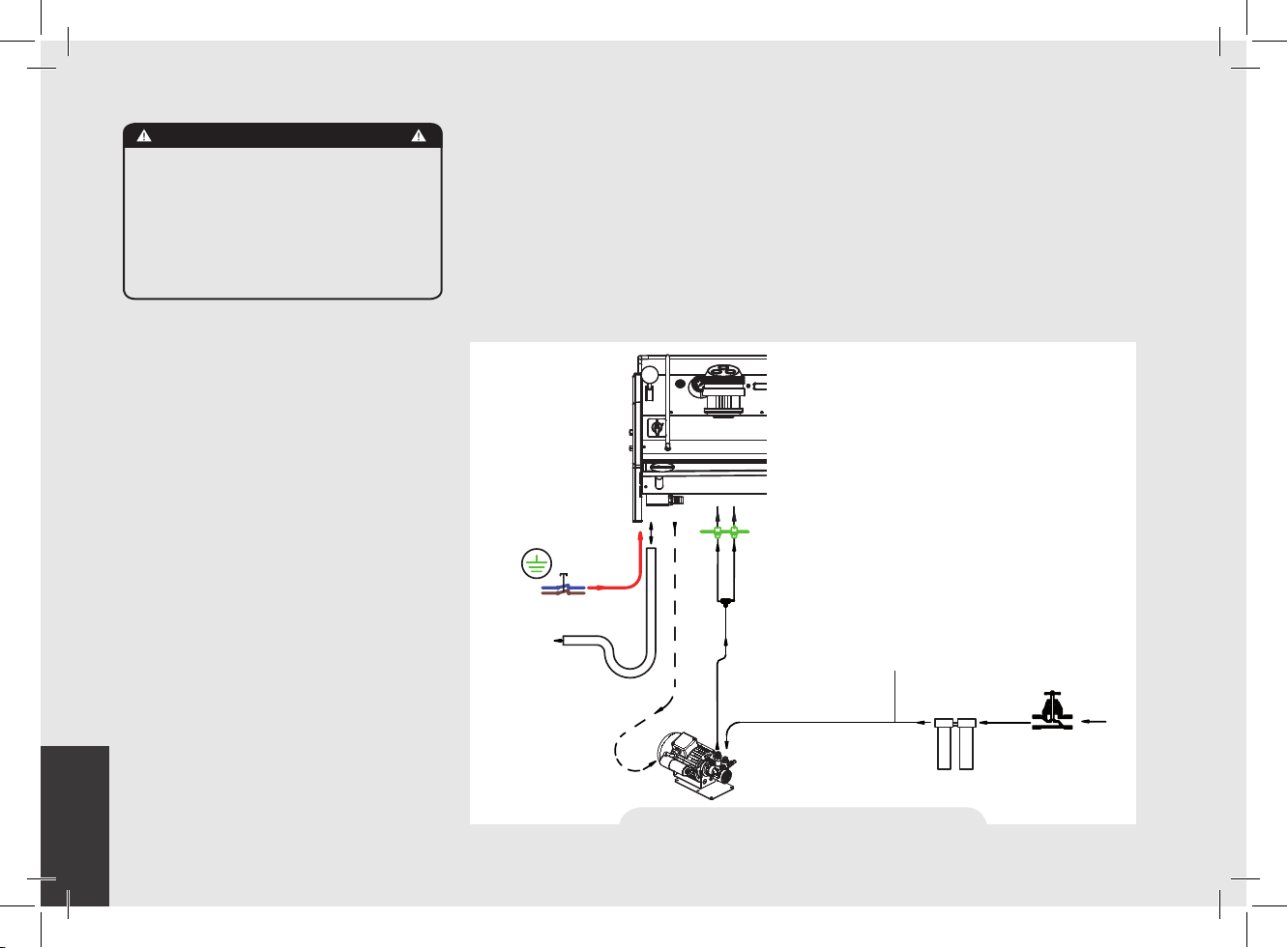
1) Installation guide
For best results, STRADA needs a
minimum ow of water in input of 100 l/h
and a pressure of 2.5 bar.
Installations that do not meet these
requirements will cause a shorter life of
the pump and may cause a high noise
level during coffee brewing.
POWER SUPPLY
CORD
AND ELECTRICAL SUPPLY CONNECTION
WASTE/DRAIN
ROTARY PUMP
STEAM
BOILER
COFFEE
BOILER
TEE FITTINGS
Fig. 3 - Installation guide - type 1
If the pressure and ow are not adequate,
air bubbles may develop within the gears.
This is called cavitation. Cavitation can
impair the performance of the espresso
machine.
If the incoming water of the espresso
machine falls outside the recommended
parameters, it is necessary to carry out one
of the following installations:
Pressure lower than 9 bar
Flow rate lower than 100 l/h
Installation with the rotary pump
immediately after the water treatment
system, upstream of the tee.
BRAIDED HOSE
WATER CHECK POINT:
FLOW RATE < 100 l/h
PRESSURE ≤ 9 BAR
WATER TREATMENT
RECOMMENDED VALUES
www.lamarzocco.com/water_calculator
MAIN WATER
SUPPLY VALVE
Page 13

EN
Pressure higher than 9 bar
Flow rate lower than 100 l/h
Installation of the pressure reducer
immediately after the water treatment
system, upstream of the rotary pump.
Installation of the rotary pump (set to 9
bar) immediately after the pressure reducer,
upstream of the tee.
POWER SUPPLY
CORD
MAIN SWITCH
AND ELECTRICAL SUPPLY CONNECTION
WASTE/DRAIN
ROTARY PUMP
Fig. 4 - Installation guide - type 2
STEAM
BOILER
COFFEE
BOILER
TEE FITTINGS
BRAIDED HOSE
WATER CHECK POINT:
FLOW RATE < 100 l/h
PRESSURE > 9 BAR
PRESSURE REDUCER
PRESSURE ≤ 9 BAR
WATER TREATMENT
RECOMMENDED VALUES
www.lamarzocco.com/water_calculator
MAIN WATER
SUPPLY VALVE
13
Page 14

EN
2) Accessories
Check the package to make sure that the
following accessories are included:
• a number of 1-dose and 2-dose
portalters orresponding to the number
of groups;
• replacement 1-dose and 2-dose lters
(one of each);
• 1 tamper;
• 1 blind lter;
• cleaning detergent, for the groups;
• 3 stainless steel braided hoses for
water connections;
• 1,5 mt of reinforced plastic tubing for
drainage;
• 1 hose clamp;
• 1 TEE Fitting.
In order to proceed with installation, it is
necessary that the following are available:
• Pipes carrying drinking water with a
3/8”G (BSP) end connection; (3/8”
Compression for USA and Canada)
• Electrical Supply according to the
specication of the espresso machine
purchased:
• Single/Three phase 220VAC - 50/60
Hz electrical connection with ground,
protected socket and approved
interlock switch
• Single phase 200VAC - 50/60 Hz
electrical connection with ground,
protected socket and approved
14
interlock switch
• Three-phase, 380VAC - 50 Hz
electrical connection with neutral +
ground, near the bench on which the
machine is installed and terminating
in a suitable protected vepole socket
equipped with an approved interlock
switch
• Waste water drain system.
3) Water test kit
In order to enable you to check if your water
supply is within the suggested ranges, La
Marzocco machines will be equipped with
two units of a quick water test kit (see image
below) including 6 test-strips and instruction
cards.
The parameters that you can measure are
Total Hardness, Total Iron, Free Chlorine,
Total Chlorine, pH & Total Alkalinity,
Chlorides.
Ideally, you should perform a test on the
water BEFORE the water treatment system
and again AFTER the water system in order
to verify if this is actually matching our
suggested ranges.
Once the test has been performed, learn
which treatment system is most appropriate
for your particular water supply by lling out
the online water calculator on our website: LA
MARZOCCO WATER CALCULATOR (http://
www.lamarzocco.com/water_calculator/).
4) Flowmeter safety removal
Before switch on, remove the clamp from
the owmeter located inside the machine, as
indicated by the adhesive label applied on
the main switch. Also remove the label from
the main switch.
Page 15

EN
5) Water supply connection
In order to connect the machine up to
the water mains proceed according to the
indications given in the chapter about
Installation and in compliance with any
local/national safety standards of the
location in which the machine is being
installed.
To guarantee a correct and safe functioning
of the machine and to maintain an
adequate performance level and a high
quality of the beverages being brewed it
is important that the incoming water be
of a hardness greater than 7°f (70ppm,
4°d) and less than 10°f (100ppm, 6°d),
pH should be between 6.5 and 8.5 and
the quantity of chlorides be less than
50mg/l . Respecting these values allows
the machine to operate at maximum
efciency. If these parameters are not
present, a specic ltration device should
be installed, while always adhering to the
local national standards in place regarding
potable water.
Then connect the inlet of the water lter/
softener (if present) to the drinking water
supply using one of the supplied stainless
steel braided hoses. Before connecting
the lter to the water pump, ush the
water supply line and the ltration system
in order to eliminate any residual particles
which could otherwise get stuck in taps or
valves thus preventing them from working
properly. Connect the water supply
connection of the espresso machine to
the water pump outlet using one of the
supplied stainless steel braided hoses.
Then connect the water pump inlet to the
water lter/softener outlet (if present).
The water pump is a differential
Note:
pressure volumetric pump and has been
designed to be used exclusively with cold
water. Make sure that water is always
present while the pump is operating,
otherwise air can be introduced into the
brew boiler causing an undesireable
condition and the pump can be damaged.
6) Electrical connections
a) Power supply cord
• This is the main power supply cable
that provides power to the entire espresso
machine. There are different types of cable
based upon the electrical requirements of
the espresso machine purchased:
• 200/220VAC 1 Phase 3-core cable
with 4/6/10mm2 cross section or AWG
12/10/8 for 2,3 4 group versions, secured
to espresso machine via a strain relief
connector
• 220VAC 3 Phase 4-core cable with 4
mm2 cross section for 2 , 3 and 4 group
versions, secured to espresso machine via
a strain relief connector
• 380 VAC 3 Phase 5-core cable with
2.5mm2 cross section for 2, 3 and 4 group
versions, secured to espresso machine via
a strain relief connector.
b) Water pump motor power cord
This is the power supply for the water
pump motor. The internal electronics will
switch the pump motor on when needed.
• 3-core cable with 1.5 mm2 cross section
or 3-core AWG 16 (for UL version) secured
to espresso machine via a strain relief
connector.
c) Quick connection between the water pump and the
espresso coffee machine
The electrical connection must be made
through the use of the connectors, as
shown in the following gures:
- View of the connectors;
Machine connector Pump connector
15
Page 16

EN
- Cable connection;
- Cable tightening;
Water specications table
T.D.S. ppm 90 150
Total Hardness ppm 70 100
+2
Total Iron (Fe
Free Chlorine (Cl
Total Chlorine (Cl
pH value 6,5 8,5
Alkalinity ppm 40 80
Chloride (Cl
N.B.: Test water quality (the warranty is void if water parameters are not within the range
specied in the section “installation”)
/Fe+3) ppm 0 0,02
) ppm 0 0,05
2
) ppm 0 0,1
2
–
) ppm not more 50
7) Waste water drain connection
The espresso machine drain is to be
connected by means of the included
reinforced plastic tubing. Connect one end
of the reinforced plastic tubing to the drain
hose connection on the left side of the
espresso machine, secure with included
hose clamp. Connect the other end to a
suitable waste water collection system.
In case such a system is not available,
drained liquids may be collected in a
suitable bucket and any necessary drain
pipe extensions shall be made using
steel-lined PVC tubing and suitable hose
clamps.
Min. Max.
16
Page 17

EN
CAUTION
Never remove the lter holder
when water is being delivered.
This operation can be extremely
dangerous since the high
pressure built-up inside the blind
lter would spray out hot and
slightly caustic water, which may
cause severe burns. The Coffee
Boiler contains water at elevated
temperature. Water temperature
over 125°F / 52°C can cause
severe burns instantly or death
from scalding.
WARNING
The machine must not be dipped
in, nor splashed with, water in
order to clean it. For cleaning
operations, please follow the
instructions listed below very
carefully.
4. Machine Operation and Coffee Preparation
WARNING
This machine is designed only for
preparing coffee and hot drinks.
IMPORTANT
To improve the avor of the espresso, the
temperature of the water in the coffee boiler
and therefore of the groups may eventually
be raised or lowered via the digital display
(please consult the Software Programming
Manual for detailed instructions).
1) Starting the espresso machine
a) Filling the boilers with water
Once the installaon procedures have
been completed, it is necessary to ll the
boiler tanks with water. Complete the
following procedure to properly ll the
boiler tanks:
• Coffee boiler
The water ows inside the coffee boiler
directly, as soon as the water system and
purier taps (if present) are opened.
Since the inow of water will compress
the air in the boiler, it will be necessary to
remove or “bleed” the air from the coffee
boilers. All air must be removed in order
to completely “saturate” the coffee boiler/
group assemblies.
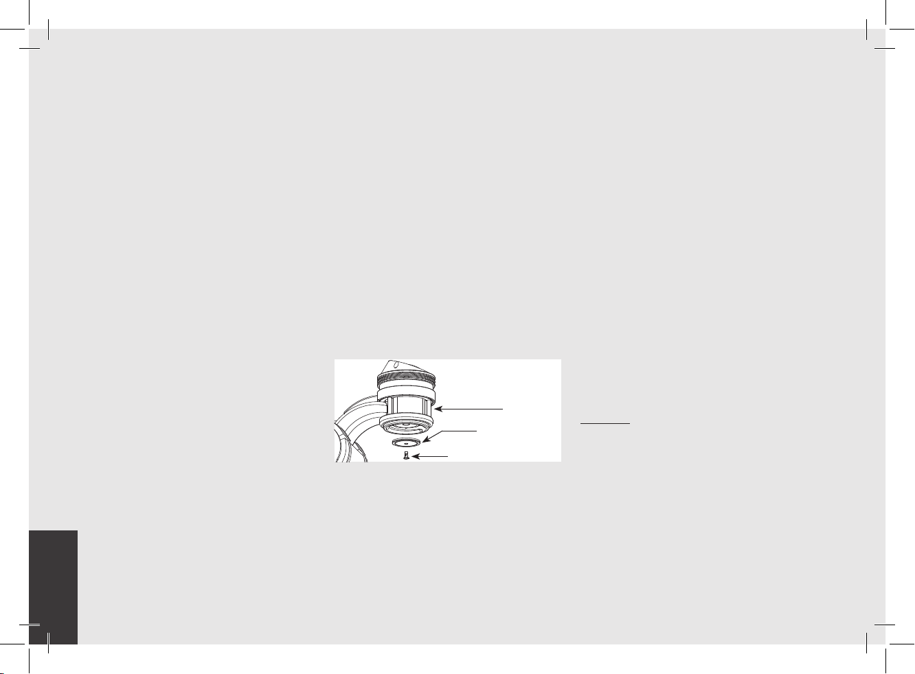
To remove the air from the boiler, or “bleed
the groups”, it will be necessary to remove
the plastic keypad from the top of the
group.
Loosen the bleed screws one at a time
to allow air to escape until water ows
from below the screw head. Tighten the
screw to stop the water from owing. Over
tightening can cause damage to the sealing
washer and the group cover. Repeat this
procedure on all groups.
• Steam boiler
Turn the main switch to position “1” or
ON, the automatic steam boiler level gauge
17
Page 18

EN
will be switched on, activating the auto-ll
solenoid valve and the motor pump. This
will ll the steam boiler to a predetermined
level and will shut off when full.
Note: Air inside the steam boiler may build
up pressure (which may be detected
through the pressure gauge).
Once the pump stops, check the display,
the message “Coffee Boiler Filled?”
should be displayed. Press
conrm that the preceding procedures are
complete.
The installation is now complete and the
espresso machine should be heating to
operating temperatures.
Display
2) Waiting for the Espresso Machine to Heat to
Operating Temperature
During this time, it may happen that
the pointer of the coffee boiler pressure
reaches as high as 14-15 bar. This may
happen anytime that the heating element
is in the “on” condition. In this case, it
to
is necessary to adjust the expansion valve
(see the picture below about the three
coffee boiler expasion valves) in such a
way that the pressure never exceeds 13
bar.
Expansion
Valve
In normal operating conditions, the coffee
boiler pressure transducer, while brewing,
can read anywhere from 0-12 bar when
brewing.
When the steam boiler reaches operating
temperature, the light on the Tea dispense
button will switch on.
3) Brewing after rst installation
Once the rst installation procedures are
nished, before proceeding with brewing
coffee, hot water and steam, please follow
these steps:
• Engage the portalters by inserting
them into each group, brew water
through each group for at least two
minutes.
• Being careful to avoid burns, turn
on each steam wand for at least one
minute.
• Turn on the hot water valve for the
time necessary to allow the following
quantities of water to be brewed:
- At least 1 liter for a 1/2 group machine
- At least 2 liters for a 3 group machine
4) Installing the portalters
Install the portalter(s) by inserting them
into the group and rotate the handle from
left to right. When the portalters are
inserted properly, you can press any of
brew buttons to start the ow of water
through the portalter. You should allow
hot water to pass through the empty
portalter(s) for a few seconds each time,
in order to preheat the portalter.
Note:
It is important to leave the portalters
installed in the espresso machine when
not in use. The portalter must remain
heated for the brew process to function
correctly.
18
Page 19

EN
Filter Basket
Porta Filter
O-ring Gasket
Double Spout
5) Brewing coffee
Now you can brew an espresso. Disengage
one of the portalters, ll the lter with
ground coffee, tamp the ground coffee
with the tamper supplied (exerting a force
of 20 kg) and re-engage the portalter to
the group. Press a button on the keypad to
begin the brewing process.
Some baristas believe it is important
Note:
to press the brewing button prior to
installing the portalter to allow the water
to ush any remaining coffee oils and
particles from the group. Some also ush
just after brewing coffee for the same
reason. Please experiment to nd the best
possible procedure for you.
6) Water pump
Whenever you are brewing coffee, and you
can adjust the pump pressure by turning
the by-pass screw (below the plug located
on the side to which the pump power
supply is connected) clockwise to increase
and counter-clockwise to reduce pressure.
Adjust pressure only when at least one
group is brewing coffee.
Note: When the heating element in the
coffee boiler is energized, the water will
expand increasing the start-up pressure.
Once the maximum pressure is reached,
the expansion (safety) valve should start
working by discharging a few drops of
water, in order to prevent such pressure
from exceeding 11-12 bar.
In case the pressure exceeds 12 bar,
you must adjust the expansion valve by
unscrewing the cap slightly. If this is not
sufcient, remove the valve and clear away
any calcium deposits. This remedy is valid
also in case the valve remains open in the
drain position (i.e. the pressure cannot
increase to 8 bar approx.).
7) General notes for coffee preparation
The portalters must remain heated since
they are at the lowest position of the
group itself, and they are partially isolated
due to the rubber gasket between them.
This can be accomplished by leaving the
portalters installed in the machine when
not in use. The portalters may also be
actively heated. This procedure may be
carried out by brewing some hot water
through the portalter then turning off the
water ow, before making coffee.
It is important to remember that coffee left
over in the lters must be removed only
when you need to prepare another cup,
and only at that time should you place a
new dose of ground coffee in the lter.
The size of the coffee granules is extremely
important in preparing a good cup of
coffee, other than the type of coffee mix
used, quite obviously. The ideal grinding
can be determined by making various
coffees using the amount of ground coffee
that you would normally use for each cup
(we recommend at least 6-7g). The best
grinding is that which allows coffee to ow
out from the lter holder spouts neither
too slowly (drop by drop) nor too quickly
(quick light brown ow). A general rule
is that a double dose should dispense
approximately 25cc or 2 uid oz. of
espresso in approximately 25 seconds.
8) Cup Warmer
Press Cup Warmer Button for enabled or
disabled the cup warmer. This function
work in two modes continuous or timed
(see the Software Programming Manual
for further instructions).
Cup Warmer Button
19
Page 20

EN
5. Dispensing Steam and Hot Water
1) Steaming milk or other liquids
In order to allow for any condensed water
in the wand to be released ALWAYS allow
some steam to be discharged by turning on
the valve before inserting the steam wand
into the pitcher of liquid to be heated.
Dip one of the 2 steam wands (part 8, page
7) which are connected to the steam valve,
into the liquid to be heated, turn the steam
knob gradually until steam comes out at the
end of the wand.
The steam will transfer heat to the liquid
raising its temperature up to boiling point.
Be careful not to allow liquid to overow in
order to avoid severe burns.
In order to prevent the heated liquid
from being sucked back into the steam
boiler it is recommended before using
the wand that you purge the steam valve
and steam wand by opening the valve for
a few seconds to allow steam to escape
to the atmosphere from the end of the
steam wand. Failure to do so can cause
the heated liquid to transfer from the
heated liquid container to the steam boiler
(via vacuum created from cooling parts).
This condition is undesireable and can
cause contamination in the steam boiler.
After use remember to purge the wand by
opening the steam valve for a few seconds,
and then clean the outside of the wand
itself with an appropriate cloth.
In order to prepare milk for making
cappuccino with the right amount of foam,
go through the following steps:
• After purging the steam wand place the
container half-full of milk underneath,
carefully open the steam valve and raise
the container so as to bring the wand end
to a point just below the surface of the
milk; at this point, move the container
up and down just enough to dip the
nozzle end in and out of the milk until
you get the right amount of foam, bring
the temperature of the milk almost up
to 149/158°F or 65/70°C. You can then
pour this milk into a cup containing warm
espresso and you will end up with a fresh
cup of cappuccino.
2) Preparing tea and other hot drinks.
TE'
You may dispense hot water by using the
xed nozzle (part 6, page 7). To dispense
hot water, press the tea water button.
This button commands hot water delivery.
The temperature of the water may be
adjusted by adjusting the mixing valve.
20
Page 21

EN
6. Maintenance and Periodic Cleaning Operations
WARNING
If the above-mentioned
instructions are not adhered
to the manufacturer cannot be
held responsible for damage to
persons or things.
WARNING
In order to prevent cracks or
leakage: do not store or install
the coffee machine in places
where temperature may cause
water in boiler or hydraulic
system to freeze.
WARNING
The machine is intended to be
permanently connected to xed
wiring, and it is advisable that
a residual current device (RCD)
with a rated residual operating
current not exceeding 30mA is
installed.
WARNING
The machine must be installed so
that qualied technical presonnel
can easily access it for eventual
maintenance.
WARNING
The machine must not be dipped
in, nor splashed with, water in
order to clean it. For cleaning
operations, please follow the
instructions listed below very
carefully.
WARNING
Do not remove the lter holder
while relative group is brewing
hot liquids.
The Coffee Boiler contains
water at elevated temperature.
Water temperature over 125°F
/ 52°C can cause severe
burns instantly or death from
scalding.
WARNING
This machine is for professional
use only and should be installed
in locations where its use and
maintenance is restriced to
trained personnel.
WARNING
Jets of water should not be used
to clean the machine, nor should
it be placed where water jets are
used.
1) Cleaning groups and drain wells
- Put a tablespoon of detergent powder
for coffee machines into the blind lter,
supplied with the machine, and tighten it
onto the group you want to clean by using
a normal lter holder.
- Turn the Paddle Valve on and off
approximately 10 times (10 seconds
intervals) on each group.
- Rinse the group using a normal lter
by running hot water through it several
times.
21
Page 22
EN
2) Cleaning lters
- Put 2 or 3 teaspoons of detergent powder
for coffee machines in about 1/2 a litre
of water inside a heat-resistant container
and boil.
- Dip lters in the boiled solution and
leave them fully submerged for about 30
minutes.
- Rinse thoroughly with clean water and
run hot water through one group several
times with the lters in place.
- Make one cup of coffee and discard in
order to remove any unpleasant avor.
3) Cleaning lter holders (portalters)
Using the proper cleaning tool (brush)
wash the lter holders under hot water,
a neutral detergent may also be used.For
extraordinary cleaning see the Portalter
Manual.
4) Cleaning the drain collector
Remove the drain tray grill at least twice
a week and clean, pull out the water drain
collector and clean it thoroughly. Inspect
and clean also the drain box and remove
any leftover grounds.
5) Cleaning the body
Wipe the stainless steel surfaces with a
soft, non abrasive cloth in the direction of
the glazing marks, if any. Do not use any
alcohol or solvents whatsoever on painted
or imprinted parts in order not to damage
them.
22
6) Cleaning the hot water and steam nozzles
Steam nozzles must be cleaned
immediately after use with a damp cloth
and by producing a short burst of steam
so as to prevent the formation of deposits
inside the nozzles themselves, which
may alter the avor of other drinks to
be heated. Hot water nozzles must be
cleaned periodically with a damp cloth.
7) Cleaning the diffuser screen
- Due to lter holder discharge operations
(subsequent to coffee brewing), a certain
amount of coffee grounds may slowly
build-up on and obstruct, even partially,
the diffuser screen. To clean it, you must
rst remove it by unscrewing the diffuser
screw.
GROUP
ASSEMBLY
DIFFUSER
SCREEN
DIFFUSER
SCREW
- Put 2 or 3 teaspoons of cleaning
detergent for coffee machines in about
1/2 a litre of water inside a heat-resistant
container and boil.
- Place the diffuser screen(s) and diffuser
screw(s) in the solution and leave them
fully submerged for about 30 minutes.
Rinse thoroughly with clean water. Install
and run hot water through each group
several times with the screen installed.
8) Water Filter/Softener
Please see the documentation accompanying
the water lter/softener for proper operating
and cleaning instructions.
• Steam boiler draining: to activate this function
you need to access the programming menu
(see p. 93). Yearly, we recommend to fully
drain the steam boiler by means of the
specic drain cock located on the side of
the boiler or under the boiler.
9) Depressurize the steam boiler
Press and hold the encoder knob to set
the espresso machine to “OFF”, then
push down the steam lever in order to
depressurize the steam boiler.
IMPORTANT
If the machine has not been used for more
than 8 hours or, in any case, after long
periods of being idle, in order to use the
machine to its full potential it is necessary
to perform some cleaning cycles before
brewing beverages as follows:
- Groups: with the portalters engaged
in the groups brew water through each for
at least two minutes
- Being careful to avoid burns, turn on
Page 23
EN
each steam wand for at least one minute.
- Turn on the hot water valve for the time
necessary to allow the following quantities
of water to be brewed:
At least 1 liter for a 1/2 group machine
At least 2 liters for a 3 group machine
If the machine is not going to be used
for long periods of time, it is advisable to
follow these safety indications:
- Disconnect the machine from the water
mains or interrupt the water connection
via a mains tap.
- Disconnect the machine from the
electrical mains.
7. De-commissioning and Demolition
1) De-commissioning and demolition
Start by setting the main switch to the “0”
or OFF position.
Disconnecting from the power outlet
Disconnect the espresso machine from
the electrical network by switching off
the associated circuit breaker or circuit
protection device. Remove the power
supply cord from the power connection.
Remove the Pump Motor Power Cord from
the water pump motor.
Disconnecting from the water system
Shut off the water supply by closing the
specic tap located upstream of the water
lter/softener inlet. Disconnect the water
pipe at the water lter/softener inlet.
Remove the hose connecting the espresso
machine to the water pump. Remove
the reinforced plastic tubing on the drain
connection.
At this point, the machine may be removed
from the bar, being very careful not to drop
it or squash your ngers.
The machine is made out of various
materials and therefore, if you do not
intend to put it back in service, it must
be taken to a special disposal company
which will select the materials which can
be recycled and discard the others.
Current regulations make it illegal to
discard such machine by leaving it on
public grounds or on any private property.
Recycling notice: Warning for the protection of the
environment.
Used Electrical and electronic waste
contains hazardous but also valuable
and scarce materials which should be
recovered and recycled properly. We kindly
ask that you contribute to the protection of
the environment and natural resources by
delivering used equipment to the relevant
recycling locations if such locations are
available in your country.
23
Page 24

EN
8. Mandatory Maintenance and Check-up Operations
These operations are in addition to the Maintenance and Periodic Cleaning Operations as specied in Chapter 6.
The following maintenance and check-up operations sould be carried out by a qualied technician.
The time required for the periodic maintenance is determinated by the quantity of daily work and/or coffee consumption.
N.B. These periodic maintenance operations are not covered by warranty.
▪ Replace group gaskets
▪ Replace diffuser screens
▪ Clean auto-ll probe
▪ Check vacuum breaker for
proper operation
▪ Inspect water inlet valve
▪ Inspect drain system for leaks
or clogs
▪ Check ow rate for each group
▪ Replace portalter baskets
▪ Inspect group valve plungers
▪ Inspect vacuum breaker
▪ Inspect expansion valve
▪ Inspect electrical wiring
condition
▪ Check the condition of the inside of boilers and if necessary rinse out with a proper cleaning product allowed for food and beverage
appliances.
▪ Check brew temperature
▪ Check that brew pressure is
at 9bar
▪ Check all switches for proper
operation
▪ Check/note water hardness
(Water quality must be within the
range of parameters specied
in the chapter on Installation,
▪ Inspect boilers safety switches
▪ Inspect electrical wiring
condition
▪ Replace over-pressure valve
(safety valve)
▪ Accurate control of the
EVERY THREE/FOUR MONTHS
EVERY YEAR (in addition to the above)
EVERY 3 YEARS (in addition to the above)
otherwise warranty is voided)
▪ Check lter basket condition
▪ Check shot volumes
▪ Test flowmeter’s ohm value
(ohm value is acceptable if
greater than 1.8 K ohm, and
less than 2.2 K ohm)
tightness at 2,4Nm of each
cable on the terminal block.
24
Page 25

EN
9. Precision Scale
WARNING
Handle with care maximum load
1Kg do not lift.
WARNING
The individual grid of the scale
is a fragile component, handle
and store with care.
WARNING
The height of the bottom tray is
xed.
1) Use precautions
Remove the adhesive label with care; if
needed, remove any adhesive residues
from the surface using a neutral detergent.
Don’t spill water onto the scale box
If needed, gently remove it with an
absorbent cloth. Should any water and/or
dirt penetrate into the holes highlighted
3
2
1
4
Fig. 5 - Precision scale - 2 and 3 brewing groups
in the gure below, gently clean and dry
them with an absorbent paper cloth.
Dirt build-up or water stagnation may
prevent the scale individual grid from
properly settling into place.
The weighing system in static conditions
(*) has a rated accuracy of ±0.5g.
For correct operation, make sure that:
Legend
1 Scale crosspiece
2 Drain grille
Scale individual grid
3
4
Removable drain tray
• Maintenance is performed properly, by
an authorized person and in the manner
prescribed in this manual;
• Please use the machine according to the
instructions specied in this manual;
• Please make sure the machine is
installed on a level and rm counter;
• Please make sure the power supply is
stable and without electrical noises.
The weighing stage is a inherently delicate,
in fact it is affected by:
• Vibration of the bench caused for
example by other devices;
• Machine vibrations caused, for example,
by the use of the adjacent group.
25
Page 26
EN
(*) Static weighing means weighing an
object whose weight is xed during the
entire weighing.
The machine is not a weighing device
certied for legal weighing.
- The weighing system is a precision device
that requires a lot of caution in terms of
use, cleaning and maintenance.
- Should the main grid or tray be removed,
ensure not to hit the load cells during the
disassembly and reassembly operations.
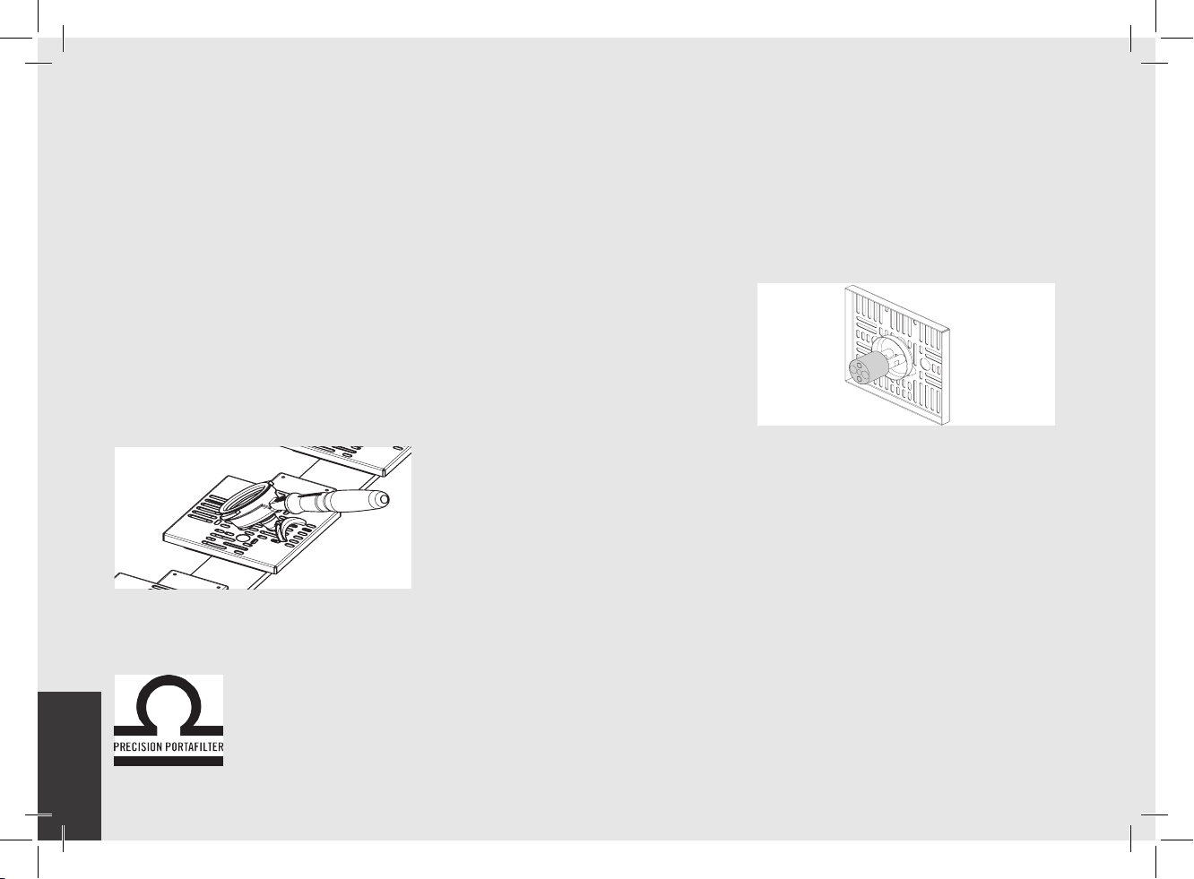
- To proceed with the weighing of the lter
holder either empty or lled with coffee
powder, place it as shown below:
- Use only lter holders with double spout;
- Do not place on the scale objects
weighing more than 1kg;
- Never load more than 1 kg, to prevent
any damage to the scales;
- Use the high precision scale with care,
avoid shocks, falling objects and sudden
load peaks;
- Any object to be weighed must be placed
correctly on the scales grid.
2) Cleaning
- The cleaning of the “individual grids”
must be performed with care, without
overloading the cells;
- For proper weighing of the lter holder,
make sure the grid is clean and dry;
- To avoid contact with dirt before placing
the lter holder, clean and dry the grid;
- Don’t wash the scale individual grids in a
dishwasher; wash them manually instead,
then immediately dry them.
If you wash the grid under a strong
water ow, remove the magnetic support
highlighted in the gure (just pull to
detach the magnets). Make sure that the
magnets are always dry and clean.
- To clean the drain tray you need to remove
the individual grids (part 3, gure 5) rst,
then the drain grille (part 2, gure 5) and
nally the tray (part 4, gure 5). Make
sure not to hit the load cells during the
disassembly and reassembly operations.
- Use only original La Marzocco lters and
lter holders, identied by the following
symbol:
26
- Please be careful during the cleaning
procedures to avoid the water dripping on
the scale and its electrical components;
Page 27

EN
3) Removing the electronic box
1
2
To remove the electronic box you need
to remove the lower front panel, unscrew
and remove the lower screws 1, loosen
the upper screws 2 without removing
them and move the scale crosspiece up.
Now you can access the electronic box or
remove it.
27
Page 28

EN
10. Software Programming Guide
Programming Introduction
Digital Display
Programming Keypad
Start Up Procedures
Shut Down Procedures
Accessing Programming Mode
Cleaning Cycles
Brewratio (ABR version)
“Barista” Programming
Program Doses
Scales (ABR version)
Tea Dose
Coffee Boiler
Pre-Infusion or Pre-Brewing
Cup Warmer
Exit Menu
page 29
page 30
page 31
page 32
page 33
page 34
page 35
page 36
page 53
page 55
page 58
page 60
page 61
page 62
“Technical” Programming
Language
Temperature Measurement Units
Name
Program Doses
Scales (ABR version)
Tea Dose
Coffee Boiler
Steam Boiler
Pre-Infusion or Pre-Brewing
Crono Function
Clock Adjust
Cup Warmer
Auto ON/OFF
Eco Mode
Coffee Dose Counter
Filter Alarm
Reset
Update Firmware
Exit Menu
page 63
page 64
page 65
page 66
page 83
page 86
page 89
page 91
page 97
page 98
page 99
page 100
page 102
page 104
page 106
page 108
page 110
page 111
page 112
28
Troubleshooting
page 113
Page 29
EN
Programming Introduction
LaMarzocco 09 :30
94.5 94.6 94 .5 SB
Description
• This espresso machine has a CPU and many congurable settings.
• Additionally, there are many feedback controls employed in this espresso machine to troubleshoot problems should they occur.
• The following is a brief introduction to the controls and display and how they interact with the operator.
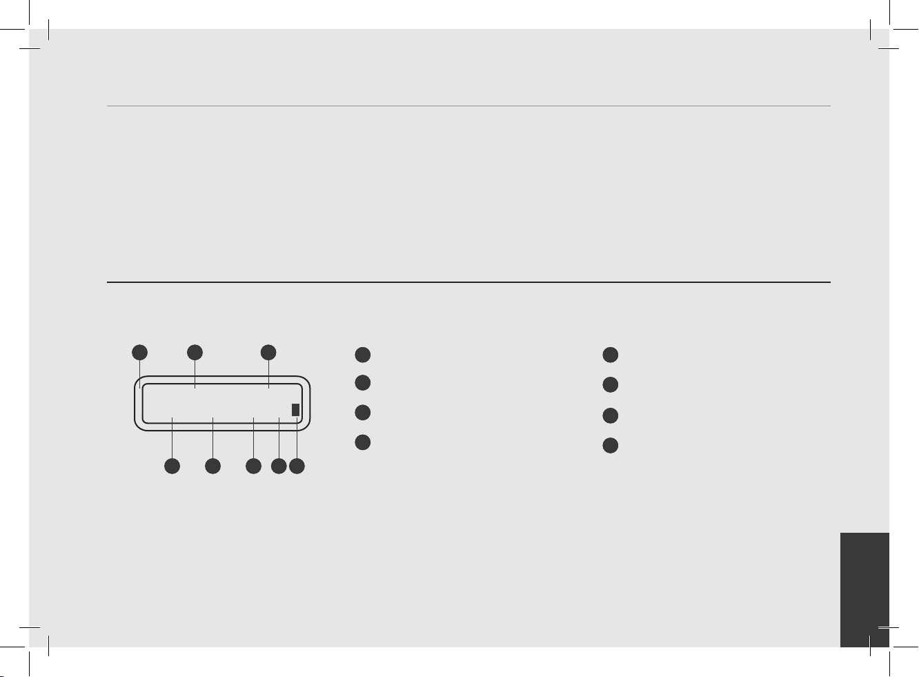
Digital Display
21
The digital display is a backlit display capable of displaying 2 lines of 16 characters. The display enables the operator to interact with
the espresso machine to visibly change parameter values. The display also provides valuable information to the operator.
There are several warnings that the can be displayed to alert the operator of an unusual condition or a fault. Additionally, simple
messages are displayed alerting the operator that an action has been started or that a process needs to begin.
3
87654
Digital display
1
Name
2
Daily timetable
3
1st group coffee boiler temperature
4
2nd group coffee boiler temperature
5
3rd group coffee boiler temperature
6
Steam Boiler
7
Heating indicator (on during heating,
8
off when the temperature has been
reached)
29
Page 30
EN
Programming Keypad
OK
OK
The keypad has two functions. The rst is for control of the espresso. The second is for programming individual software parameters.
The programming of the individual parameters is possible only using the buttons in the group 1 (group starting from the left).
30
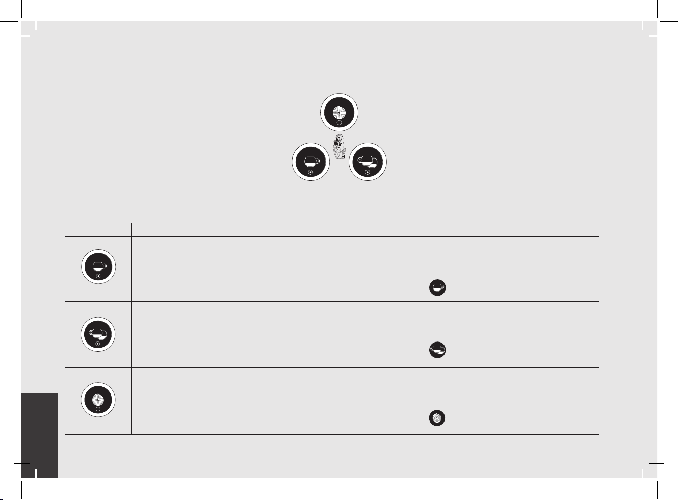
Button
OK
Description
This button is used to control the brewing of the single espresso. It is also used in the programming of the individual
parameters such as the “back” button in the menu.
For simplicity's sake in this manual it will be represented by this symbol
This button is used to control the brewing of the double espresso. It is also used in the programming of the
individual parameters such as the “forward” button in the menu.
For simplicity's sake in this manual it will be represented by this symbol
This button is used for a continuous control of the brewing of the espresso. It is also used in the programming of
the individual parameters such as the “enter” button in the menu.
For simplicity's sake in this manual it will be represented by this symbol
with the name T1.
with the name T2.
with the name T3.
Page 31

EN
Display
Operating Procedure
Description
SB FI LLED?
Turning the Espresso
Machine On
Turn the Main Switch to the 1 position.
131
To continue with the start up process, press the T3 button
2
The following is the procedure for turning
on the power to the espresso machine.
• Please follow the procedures carefully
to avoid any damage to the espresso
machine.
after lling the steam boiler.
Start Up Procedures
• Proceed checking for water connection
to the espresso machine.
• Proceed making sure you have lled the
boilers.
GROUPS BLED?
LaMarzocco 00:00
CBO 93.8°C SBO
To continue with the start up process, press the T3 button
The rectangles next to CB and SB indicate the warming up of the water contained in the boilers. When the set
4
temperature is reached, these rectangles turn off and all the lights of the buttons turn on. Now the machine
is ready for use. During the normal operation of the machine, the ashing of the rectangles indicates the
intermittent heating necessary for maintaining the temperature.
NOTE: Ensure all air is removed from the group prior to staring the espresso machine.
This only needs to be completed once during the initial setup or when water is drained from the coffee boiler.
Instructions for bleeding the groups of air can be found in the Installation Guide.
after the saturation of the coffee boiler.
WARNING
HAZARDOUS VOLTAGE DISCONNECT FROM POWER
SUPPLY BEFORE SERVICING
31
Page 32

EN
Display Operating Procedure
Description
Shut Down Procedures
Turning the Espresso
Machine Off
OFF 00:00
The following is the procedure for turning
off power to the espresso machine.
• Please follow the procedures carefully
to avoid any damage to the espresso
machine.
• This machine has two off settings. One
setting turns off all of the components
in the espresso machine and the other
turns off power to the complete espresso
machine.
LaMarzocco 09:30
94.5 94.6 94.5 SB
OFF 00:00
32
The following is the procedure for safely turning off the espresso machine.
1
Press and hold the buttons T2
2
This is the OFF setting used in the normal operating conditions.
3
During servicing or other conditions that warrant it, the main switch should be turned to the 0 position.
4
The espresso machine is off and display should be blank. It is important to follow this procedure when turning
off the machine. Failure to do so can damage the electronics.
and T3 at the same time. The display changes to the following:
HAZARDOUS VOLTAGE DISCONNECT FROM POWER
WARNING
SUPPLY BEFORE SERVICING
Page 33

EN
Display
Operating Procedure
Description
Accessing Programming Mode
Programming Mode
LaMarzocco 09:30
94.5 94.6 94.5 SB
LaMarzocco 09:30
94.5 94.6 94.5 SB
Program
Dose
Press Enter
To Exit
LaMarzocco 00:00
CB 9 3.8°C SB
Enter Password
While the espresso machine is on, press and hold the button T3 . After approximately 5 seconds the fol-
1
lowing display appears.
This is the “Barista” programming level. To program the brewing amount for each button, to set the coffee
2
boilers, the pre-infusion, and to enable/disable the resistance of the cup warmer if present.
To exit the programming mode, scroll to the exit menu, using the buttons T1 or T2 . Press the T3
3
1
2
button to conrm the exit, or press at the same time the buttons T2 and T3.
While the espresso machine is on, press and hold the button T3 . After approximately 10 seconds the
following display appears.
This is the “Technical” programming level. Enter the password and press the buttons and T2 to move
between the available parameters, press the T3 button to conrm.
• To change the values of any parameter
• There are two levels within the
• The two programming levels are as
• Barista Programming - The parameters
the operator must rst enter into the
programming mode.
programming mode that allow the
programming of specic parameters.
follows:
contained within this level are ones
the operator can change to affect the
“Barista” Programming Level
“Technical” Programming Level
quality of the espresso.
No password is required for access.
• Technical Programming - The parameters
contained within this level are ones
the operator can change to affect the
performance of the espresso machine.
These parameters are set in the factory
and their adjustment requires the
intervention of a service technician La
Marzocco reccomends that no changes
are made at this level. The Technician
Password is required for access.
Note: You must scroll to the exit menu to exit the programming mode, or press at the same time the buttons T2
and T3.
33
Page 34

EN
Display Operating Procedure
Description
Cleaning Cycles
Cleaning Cycles
Backflushing
GR1
• This parameter allows the operator
• This espresso machine has a group
to carry out the washing of the coffee
groups, in an automatic way, by running
multiple cleaning cycles.
rinsing function (rinsing jets) integrated
in the electronics.
• The rinsing procedure is provided to give
the operator more exibility and freedom
with regard to this operation.
GR1
Backflushing
34
When the espresso machine is on, to enable the washing procedure press and hold at the same time the buttons
1
T1
This activates the washing procedure of each group.
2
When activated, the water pump comes into operation, and the electric valve of the specic group being
washed will turn on and off the cycle. There are about 10 preset cycles with an interval of 4 seconds. To
manually stop the rinsing, press any key.
NOTE: In order to properly rinse the groups, put a small amount of detergent in a blind portalter basket and
insert it in the group to be rinsed before activating the rinsing process.
and T3 .
MOST DETERGENTS CAUSE FOAMING DURING THE CLEANING PROCESS. THIS FOAM COLLECTS AT THE DRAIN BOx AND
CAN PROHIBIT WASTE WATER FROM DRAINING PROPERLY. RINSE ONLY ONE GROUP AT A TIME.
RINSING MULTIPLE GROUPS SIMULTANEOUSLY COULD CAUSE THE DRAIN BOx TO OVERFLOW.
WARNING
Page 35

EN
Display
Operating Procedure
Description
“Barista” Programming
(only on ABR espresso machine models)
PF 0s 0s
0.0 0.0 0.0
LaMarzocco 09:30
94.5 94.6 94.5 SB
PF 0s 0s
0.0 0.0 0.0
LaMarzocco 00:00
CB 9 3,8°C SB
COF 0s 0s
0.0 0.0 0.0
Brewratio
The procedure for weighing the lter
• This parameter records the values for
• These values can be changed even
When the espresso machine is on, press and hold the button T2 . After about 5 seconds the following
1
screen is displayed.
When the value is no longer ashing, place the empty lter holder on the appropriate seat of the grid as
2
described in chapter 9. The value is automatically recorded. (*)
Press and hold the button T1
3
When the value is no longer ashing, place the lter holder lled with coffee powder on the appropriate seat of
4
the grid as described in chapter 9. The value is automatically recorded.
holder either empty or lled with coffee
powder is shown below.
the brew according to the brew ratio
technology.
manually by entering the software
settings.
. After about 5 seconds the following screen is displayed.
• To brew in brew ratio mode, set this
mode by entering the software settings.
• Brew ratio: this mode is the ratio between
the coffee powder and the weight of the
drink
This procedure can be repeated for all the brewing groups.
(*) This procedure must be performed at the rst installation, though it is possible to repeat it anytime (for
example if you get a new portalter set).
35
Page 36

EN
Display Operating Procedure
Description
“Barista” Programming
Program Dose
Group Dose
Settings
• This parameter allows the operator to
• The brewing amount can be set in terms
• Once programmed, the button remains
program the amount of coffee (brewing
amount) for each button on the
keyboard.
of time (sec. ) or pulses. This number
refers to the number of pulses that the
owmeter sends to the CPU.
lighted.
• It is possible to set the dose for both a
short and a long shot on the same key.
• The setting of the rst group is
automatically copied to the subsequent
groups.
• It is possible to set each key individually,
in this case the dose of the rst group
will no longer be used.
• It is possible to copy the doses of any
key to the others.
LaMarzocco 09:30
94.5 94.6 94.5 SB
Group Dose
Settings
Program
Volume Dose
Press Enter
To Exit
Push T o S top
20 Pulses 1s
G1B 1 Saved
20 Pul ses
1
When the espresso machine is turned on, press and hold the T3 button to access the “Barista” programming.
After about 5 seconds the following screen is displayed.
Press the T3 button
2
Press the T3 button
3
On each button you can set two doses, one for a short shot, one for a long shot.
4
To set the brewing time of a short shot, press and release the button immediately, press again to stop and store
the desired dose.
To set the brewing time of a long shot, press and hold the button for about 2 seconds, press and release the
button immediately to store the desired dose.
The two doses of each key can be set independently from one another.
If one of the two doses is not set or does not refer to the corresponding dose of the rst group, it will work as
continuous dose.
to enter the doses programming procedure.
to start the doses programming procedure.
36
Page 37

EN
Display
Operating Procedure
Description
“Barista” Programming
Press Enter
Program Dose
Group Dose
To Exit
• This parameter allows the operator to
Settings
Press the T3 button to return to the doses programming.
5
• The brewing amount can be set in terms
• Once programmed, the button remains
program the amount of coffee (brewing
amount) for each button on the
keyboard.
of time (sec. ) or pulses. This number
refers to the number of pulses that the
owmeter sends to the CPU.
lighted.
• It is possible to set the dose for both a
short and a long shot on the same key.
• The setting of the rst group is
automatically copied to the subsequent
groups.
• It is possible to set each key individually,
in this case the dose of the rst group
will no longer be used.
• It is possible to copy the doses of any
key to the others.
Group Dose
Exit
LaMarzocco 09:30
94.5 94.6 94.5 SB
Press T1
6
“Barista” programming.
Press T1
7
Press T2
8
espresso machine.
or T2 to continue with the programming of the other parameters.
and T3 at the same time to exit the programming mode and return to the normal use of the
or T2 until the display shows the exit menu, press the T3 button to return to the
37
Page 38

EN
Display Operating Procedure
Description
“Barista” Programming
(only on ABR espresso machine models)
LaMarzocco 09:30
94.5 94.6 94.5 SB
Group Dose
Settings
Mass Dose
Press Enter
Push T o S top
G1B 1 Saved
Program Dose
Group Dose
Program
To Exit
20.0g
20.0g
Scales
Settings
1
When the espresso machine is turned on, press and hold the T3 to access the “Barista” programming. After
about 5 seconds the following screen is displayed.
Press the T3
2
Press the T3
3
On each button you can set two doses, one for a short shot, one for a long shot.
4
To set the brewing weight of a short shot, press and release the button immediately, press again to stop and store
the desired dose.
To set the brewing weight of a long shot, press and hold the button for about 2 seconds, press and release the
button immediately to store the desired dose.
The two doses of each key can be set independently from one another.
• This parameter allows the operator to
• Once programmed, the button remains
to enter the doses programming procedure.
to start the doses programming procedure.
program the amount of coffee (brewing
weight) for each button on the keyboard.
lighted.
• It is possible to set the dose for both a
short and a long shot on the same key.
• It is possible to copy the doses of any
key to the others.
38
Page 39

EN
Display
Operating Procedure
Description
“Barista” Programming
(only on ABR espresso machine models)
Press Enter
To Exit
Group Dose
Exit
LaMarzocco 09:30
94.5 94.6 94.5 SB
Program Dose
Scales
Group Dose
Settings
Press the T3 to return to the doses programming.
5
Press T1
6
programming.
Press T1
7
Press T2
8
espresso machine.
• This parameter allows the operator to
• Once programmed, the button remains
program the amount of coffee (brewing
weight) for each button on the keyboard.
lighted.
or T2 until the display shows the exit menu, press the T3 to return to the “Barista”
or T2 to continue with the programming of the other parameters.
and T3 at the same time to exit the programming mode and return to the normal use of the
• It is possible to set the dose for both a
short and a long shot on the same key.
• It is possible to copy the doses of any
key to the others.
39
Page 40

EN
Display Operating Procedure
Description
“Barista” Programming
(only on ABR espresso machine models)
LaMarzocco 09:30
94.5 94.6 94.5 SB
Group Dose
Settings
Settings
Group 1 Mode
Program Dose
Group Dose
G1 Dose
PULSES
Scales
Settings
1
When the espresso machine is turned on, press and hold the T3 to access the “Barista” programming. After
about 5 seconds the following screen is displayed.
2
Press the T3
3
Press the button T1
• This parameter allows the operator to
• PULSE mode: control of doses in volume
• MASS mode: control of doses in mass
• BREW RATIO mode: ratio between the
to enter the doses programming procedure.
or T2 to display the following menu.
select the coffee brewing mode among
those available: pulse, mass and brew
ratio.
coffee powder and the weight of the
drink
4
Press the T3
MASS and BREWRATIO.
to access the menu, then navigate using T1 andT2 to choose between PULSES,
40
Page 41

EN
Display
Operating Procedure
Description
“Barista” Programming
(only on ABR espresso machine models)
Exit
Group 1
LaMarzocco 09:30
94.5 94.6 94.5 SB
Program Dose
Scales
Group Dose
Settings
Press T1 or T2 until the display shows the exit menu, press the T3 to return to the “Barista”
5
programming.
Press T1
6
Press T2
7
espresso machine.
• This parameter allows the operator to
• PULSE mode: control of doses in volume
• MASS mode: control of doses in mass
• BREW RATIO mode: ratio between the
or T2 to continue with the programming of the other parameters.
and T3 at the same time to exit the programming mode and return to the normal use of the
select the coffee brewing mode among
those available: pulse, mass and brew
ratio.
coffee powder and the weight of the
drink
41
Page 42

EN
Display Operating Procedure
Description
“Barista” Programming
Program Dose
G1 Dose
Settings
• This parameter allows the operator to
view and manually change each dose for
each key.
• For greater accuracy and consistency of
the doses, it is recommended that you
set each key.
LaMarzocco 09:30
94.5 94.6 94.5 SB
Group Dose
Settings
Program
Volume Dose
G1 Dose
Settings
G1B 1 Dose
263 Pul ses
G1B 1 Long Dose
363 Pul ses
G1B 1 Dose
Continuous
G1T3 Mode
CONTINUOUS
When the espresso machine is turned on, press and hold the T3 button to access the “Barista” programming.
1
After about 5 seconds the following screen is displayed.
Press the T3 button
2
Press the button T1
3
4
Press the button T3
Press the button T1
5
will blink. Use the button T1
to enter the doses programming procedure.
or T2 to display the following menu.
view and/or change the dose of each key.
or T2 to view the dose of each key. Pressing the button T3 , the dose value
or T2 to change the value, press the button T3 to conrm the
desired value.
It is possible to set the value of the pulses to zero to choose a continuous dose.
Press the button T3
to enter the menu, then navigate using T1 and T2 to choose between
CONTINUOUS or 3 SEC RINS.
42
Page 43

EN
Display
Operating Procedure
Description
“Barista” Programming
Program Dose
G1 Dose
Settings
• This parameter allows the operator to
view and manually change each dose for
each key.
• For greater accuracy and consistency of
the doses, it is recommended that you
set each key.
G1B 1 Dose
Use Group 1
Exit
Group 1
Group Dose
Exit
LaMarzocco 09:30
94.5 94.6 94.5 SB
Except for the rst group, you can set the function USE GROUP 1 for each key.
This option allows to use the corresponding dose of the rst group instead of setting it.
The setting of the rst group is automatically copied to the subsequent groups.
Press the button T3
6
Press the T3 button
7
Press T1
8
Press T2
9
espresso machine.
or T2 to continue with the programming of the other parameters.
and T3 at the same time to exit the programming mode and return to the normal use of the
to exit the submenu.
to return to the doses programming.
43
Page 44

EN
Display Operating Procedure
Description
“Barista” Programming
(only on ABR espresso machine models)
Program Dose
• This parameter allows the operator to
view and manually change each dose for
each key.
G1 Dose
Settings
LaMarzocco 09:30
94.5 94.6 94.5 SB
Group Dose
Settings
Program
Volume Dose
G1 Dose
Settings
G1B 1 Mass
20.0g
G1B 1 Long Mass
30.0g
G1B 1 Mass
0.0g
G1T3 Mode
CONTINUOUS
When the espresso machine is turned on, press and hold the T3 button to access the “Barista” programming.
1
After about 5 seconds the following screen is displayed.
Press the T3 button
2
Press the button T1
3
4
Press the button T3
Press the button T1
5
will blink. Use the button T1
to enter the doses programming procedure.
or T2 to display the following menu.
view and/or change the dose of each key.
or T2 to view the dose of each key. Pressing the button T3 , the dose value
or T2 to change the value, press the button T3 to conrm the
desired value.
It is possible to set the value of the pulses to zero to choose a continuous dose.
Press the button T3
to enter the menu, then navigate using T1 and T2 to choose between
CONTINUOUS or 3 SEC RINS.
44
• For greater accuracy and consistency of
the doses, it is recommended that you
set each key.
Page 45

EN
Display
Operating Procedure
Description
“Barista” Programming
(only on ABR espresso machine models)
Exit
Group 1
Group Dose
Exit
LaMarzocco 09:30
94.5 94.6 94.5 SB
Program Dose
G1 Dose
Settings
Press the button T3 to exit the submenu.
6
Press the T3 button
7
Press T1
8
Press T2
9
espresso machine.
• This parameter allows the operator to
view and manually change each dose for
each key.
to return to the doses programming.
or T2 to continue with the programming of the other parameters.
and T3 at the same time to exit the programming mode and return to the normal use of the
• For greater accuracy and consistency of
the doses, it is recommended that you
set each key.
45
Page 46

EN
Display Operating Procedure
Description
“Barista” Programming
(only on ABR espresso machine models)
Program Dose
Scales
• This parameter allows the operator to
view and manually change each dose for
each key.
G1 Dose
Settings
LaMarzocco 09:30
94.5 94.6 94.5 SB
Group Dose
Settings
Program
Volume Dose
G1 Dose
Settings
G1B1 Brew Ratio
1:2.0 0
G1 PF Mass
800.0g
1
When the espresso machine is turned on, press and hold the T3 to access the “Barista” programming.
After about 5 seconds the following screen is displayed.
Press the T3
2
Press the button T1
3
4
Press the button T3
Press the button T1
5
will blink. Use the button T1
desired value.
Press the button T1
6
value will blink. Use the button T1
the desired value.
to enter the doses programming procedure.
or T2 to display the following menu.
view and/or change the dose of each key.
or T2 to view the dose of each key. Pressing the button T3 , the dose value
or T2 to change the value, press the button T3 to conrm the
or T2 to view the portalter mass of each group. Pressing the button T3 , the
or T2 to change the value, press the button T3 to conrm
46
• For greater accuracy and consistency of
the doses, it is recommended that you
set each key.
Page 47

EN
Display
Operating Procedure
Description
“Barista” Programming
(only on ABR espresso machine models)
G1 Cof fee Mass
14.0 g
G1T3 Mode
CONTINUOUS
Exit
Group 1
Group Dose
Exit
Program Dose
Scales
G1 Dose
Settings
Press the button T1 or T2 to view the coffee mass of each group. Pressing the button T3 , the
7
value will blink. Use the button T1
the desired value.
Press the button T3
CONTINUOUS or 3 SEC RINS.
Press the button T3
8
Press the T3
9
• This parameter allows the operator to
view and manually change each dose for
each key.
or T2 to change the value, press the button T3 to conrm
to enter the menu, then navigate using T1 and T2 to choose between
to exit the submenu.
to return to the doses programming.
• For greater accuracy and consistency of
the doses, it is recommended that you
set each key.
47
Page 48

EN
Display Operating Procedure
Description
“Barista” Programming
(only on ABR espresso machine models)
LaMarzocco 09:30
94.5 94.6 94.5 SB
Program Dose
Scales
G1 Dose
Settings
10
Press T1 or T2 to continue with the programming of the other parameters.
Press T2
11
espresso machine.
• This parameter allows the operator to
• For greater accuracy and consistency of
and T3 at the same time to exit the programming mode and return to the normal use of the
view and manually change each dose for
each key.
the doses, it is recommended that you
set each key.
• The dose can be set by pulses or by
mass (weight).
48
Page 49

EN
Display
Operating Procedure
Description
“Barista” Programming
LaMarzocco 09:30
94.5 94.6 94.5 SB
Group Dose
Settings
Program Dose
Copy
Dose
When the espresso machine is turned on, press and hold the T3 button to access the “Barista” programming.
1
After about 5 seconds the following screen is displayed.
Press the T3 button
2
• This parameter allows the operator to
copy the doses present of each key to
the others.
to enter the doses programming procedure.
Program
Volume Dose
Copy
Dose
Push Button
to Copy
Push to Paste
Enter to Ex it
Group Dose
Exit
Press the button T1
3
Press the button T3
4
Press the key whose setting you want to copy. Now all the keys will ash.
5
Press the key where you want to paste the previously copied setting. Successful programming is indicated by
6
the xed lighting of the key. It is possible to repeat this procedure on any key.
Press T1
7
“Barista” programming.
or T2 until the display shows the exit menu, press the T3 button to return to the
or T2 to display the following menu.
to start the dose copy procedure.
49
Page 50

EN
Display Operating Procedure
Description
“Barista” Programming
Program Dose
Copy
Dose
• This parameter allows the operator to
copy the doses present of each key to
the others.
LaMarzocco 09:30
94.5 94.6 94.5 SB
50
8
Press T1 or T2 to continue with the programming of the other parameters.
Press T2
9
espresso machine.
and T3 at the same time to exit the programming mode and return to the normal use of the
Page 51

EN
Display
Operating Procedure
Description
“Barista” Programming
LaMarzocco 09:30
94.5 94.6 94.5 SB
Program Dose
Reset
Volume Doses
When the espresso machine is turned on, press and hold the T3 button to access the “Barista” programming.
1
After about 5 seconds the following screen is displayed.
• This parameter allows the operator to
cancel all the doses set.
Group Dose
Settings
Program
Volume Dose
Reset
Volume Doses
Resetting
Doses...
Group Dose
Exit
Press the T3 button
2
Press the button T1
3
Press the button T3
4
Now all settings are cleared.
5
Press T1
6
“Barista” programming.
or T2 until the display shows the exit menu, press the T3 button to return to the
to enter the doses programming procedure.
or T2 to display the following menu.
to conrm the procedure.
51
Page 52

EN
Display Operating Procedure
Description
“Barista” Programming
Program Dose
Reset
Volume Doses
• This parameter allows the operator to
cancel all the doses set.
LaMarzocco 09:30
94.5 94.6 94.5 SB
52
7
Press T1 or T2 to continue with the programming of the other parameters.
Press T2
8
espresso machine.
and T3 at the same time to exit the programming mode and return to the normal use of the
Page 53

EN
Display
Operating Procedure
Description
“Barista” Programming
(only on ABR espresso machine models)
LaMarzocco 09:30
94.5 94.6 94.5 SB
Scales
Configuration
Scale B1 short
Stop 0.7 g early
Scale B1 long
Stop 0.7 g early
Scale Tar e Time
3.0s
Program Scales
Scales
Configuration
When the espresso machine is turned on, press and hold the T3 to access the “Barista” programming.
1
After about 5 seconds the following screen is displayed.
Press the T3 button
2
Press the T3 button
3
desired value. This parameter is common to all groups.
Press the T3 button
4
set the desired value. This parameter is common to all groups.
• This parameter enables the technician
- Enabling/disabling the offset
- Setting the weight reading time;
- Calibrating the scales.
to enter the doses programming procedure.
to enter the menu, then navigate using the T1 and T2 buttons to set the
to enter the menu, navigate the parameters using the buttons T1 and T2 to
to set some scale parameters like:
parameter;
53
Page 54

EN
Display Operating Procedure
Description
“Barista” Programming
(only on ABR espresso machine models)
Scale Settings
LaMarzocco 09:30
94.5 94.6 94.5 SB
Program Scales
Scales
Configuration
Press the T3 button to return to the “Barista” programming.
Exit
5
Press T1
6
Press T2
7
espresso machine.
• This parameter enables the technician
- Enabling/disabling the offset
- Setting the weight reading time;
- Calibrating the scales.
or T2 to continue with the programming of the other parameters.
and T3 at the same time to exit the programming mode and return to the normal use of the
to set some scale parameters like:
parameter;
54
Page 55

EN
Display
Operating Procedure
Description
“Barista” Programming
LaMarzocco 09:30
94.5 94.6 94.5 SB
Tea Dose
• This parameter allows the operator to
program the amount of water (brewing
amount) for the tea button.
• This feature can be enabled or disabled.
Tea
Settings
When the espresso machine is turned on, press and hold the T3 button to access the “Barista” programming.
1
After about 5 seconds the following screen is displayed.
Program
Dose
Tea
Settings
Tea Dose
ENABLED
Program
Tea Dose
Program
Long T ea Dose
Move between the parameters using the buttons T1
2
Press the T3 button
3
Press the T3 button
4
to select ENABLED or DISABLED , press the T3 button to conrm the option.
You can set two doses on the tea button by selecting either Tea Dose or Long Tea Dose. Press T3 button
5
to start the dose setting procedure.
to enter the menu.
to enter the menu, move between the parameters using the buttons T1 and T2
and T2 until the display shows:
55
Page 56

EN
Display Operating Procedure
Description
“Barista” Programming
Tea Dose
Tea Dose
Settings
• This parameter allows the operator to
program the amount of water (brewing
amount) for the tea button.
• This feature can be enabled or disabled.
Press T ea Button
To Sto p
Press T ea Button
To Progr am
Tea Dose Saved
5.0 Seconds
Tea Dose
5.0s
Long T ea Dose
10.0s
To program the brewing time, press the tea button to start and then press it again to stop when the desired
6
dose is achieved.
Now the saved brewing time is displayed.
Press T1
7
value will blink. Use the button T1
conrm the desired value.
Press T1
8
dose value will blink. Use the button T1
to conrm the desired value.
or T2 to display the dose of the tea button. Pressing the button T3 button , the dose
or T2 to change the value, press the button T3 button to
or T2 to display the long dose of the tea button. Pressing the button T3 button , the
56
or T2 to change the value, press the button T3 button
Page 57

EN
Display
Operating Procedure
Description
“Barista” Programming
Tea Dose
Tea
Settings
• This parameter allows the operator to
program the amount of water (brewing
amount) for the tea button.
• This feature can be enabled or disabled.
Tea Dose
Exit
LaMarzocco 09:30
94.5 94.6 94.5 SB
Press the T3 button
9
Press T1
10
Press T2
11
espresso machine.
to return to the “Barista” programming.
or T2 to continue with the programming of the other parameters.
and T3 at the same time to exit the programming mode and return to the normal use of the
57
Page 58

EN
Display Operating Procedure
Description
“Barista” Programming
Coffee Boiler
Coffee Boiler
Settings
• This parameter allows the operator to
enable/disable the coffee boiler.
• This parameter allows the operator to
program the coffee boiler temperature.
Each group can have a different
programming.
LaMarzocco 09:30
94.5 94.6 94.5 SB
Program
Dose
Coff ee Bo iler
Settings
Coff ee Bo iler 1
ENABLED
CB1 Temperature
93.1°C 9 3.3°C
When the espresso machine is turned on, press and hold the T3 button to access the “Barista” programming.
1
After about 5 seconds the following screen is displayed.
Move between the parameters using the buttons T1
2
Press the T3 button
3
Press the T3 button
4
to select ENABLED or DISABLED , press the T3 button to conrm the option. In the case of op-
tion enabled you can set the following parameters.
Press the T3 button
5
temperature, press the T3 button
boilers you can set the temperature also on the coffee boiler. The temperature indicated on the left is the
actual temperature of the group while the temperature on the right is the set temperature.
to enter the menu.
to enter the menu, move between the parameters using the buttons T1 and T2
to enter the menu, move with the buttons T1 and T2 to set the desired
to conrm the value. In the case of espresso machine a multiple
58
and T2 until the display shows:
Page 59

EN
Display
Operating Procedure
Description
“Barista” Programming
CB Sett i ngs
Coffee Boiler
Coffee Boiler
Settings
To exit the menu move between the parameters using the buttons T1 and T2 until the exit menu is
Exit
6
displayed. Press the T3 button
• This parameter allows the operator to
enable/disable the coffee boiler.
to return to the “Barista” programming.
• This parameter allows the operator to
program the coffee boiler temperature.
Each group can have a different
programming.
LaMarzocco 09:30
94.5 94.6 94.5 SB
Press T1
7
Press T2
8
espresso machine.
or T2 to continue with the programming of the other parameters.
and T3 at the same time to exit the programming mode and return to the normal use of the
59
Page 60

EN
Display Operating Procedure
Description
“Barista” Programming
Pre-Infusion or Pre-Brewing
Pre-Wet
Settings
• This parameter allows the operator to
• Pre-brewing has only two values to be
program the time of pre-brewing of
water with the coffee. Each group can
have a different programming.
adjusted for each group. The time (in
seconds) for which the brewing valve
is open during the pre-brewing cycle
and the time (in seconds) for which
the brewing valve is closed during the
pre-brewing cycle; during this time the
pump is active. Once the pre-brewing
cycle is over, the normal brewing cycle
will continue until the end.
• For an espresso machine composed
of three groups, they are identied as
Group 1, Group 2 and Group 3.
LaMarzocco 09:30
94.5 94.6 94.5 SB
Program
Dose
Pre-Wet
Settings
Group 1 Pre-Wet
0s Wet 0s Hold
Pre-Wet Sett ings
Exit
LaMarzocco 09:30
94.5 94.6 94.5 SB
When the espresso machine is turned on, press and hold the T3 button to access the “Barista” programming.
1
After about 5 seconds the following screen is displayed.
Move between the parameters using the buttons T1
2
Press the T3 button
3
Press T1
4
By pressing the T3 button
that you want to set, press T3
To exit the menu move between the parameters using the buttons T1
5
displayed. Press the T3 button
Press T1
6
Press T2
7
espresso machine.
or T2 to select the group whose parameters you want to set.
or T2 to continue with the programming of the other parameters.
and T3 at the same time to exit the programming mode and return to the normal use of the
to enter the menu.
the rst value will blink. Use the buttons T1 and T2 to reach the value
to conrm. Repeat this operation to set the second value.
to exit the menu.
60
and T2 until the display shows:
and T2 until the exit menu is
Page 61

EN
Display
Operating Procedure
Description
“Barista” Programming
LaMarzocco 09:30
94.5 94.6 94.5 SB
Cup Warmer
• This parameter allows the operator to
enable or disable the cups heating
function.
• This function is displayed only on the
models of espresso machine equipped
with this accessory.
Cup Warmer
DISABLED
When the espresso machine is turned on, press and hold the T3 button . After about 5 seconds the following
1
screen is displayed.
Program
Dose
Cup Warmer
DISABLED
Move between the parameters using the buttons T1
2
Press the T3 button
3
to select ENABLED or DISABLED , press the T3 button to conrm the option.
to enter the menu, move between the parameters using the buttons T1 and T2
and T2 until the display shows:
61
Page 62

EN
Display Operating Procedure
Description
“Barista” Programming
Exit
Menu
Exit Menu
• This parameter allows the operator to
Exit
Menu
Press the T3 button to exit the “Barista” programming and return to the normal use of the espresso
1
machine.
exit the “Barista” programming and
return to the normal use of the espresso
machine.
LaMarzocco 09:30
94.5 94.6 94.5 SB
62
Alternatively, you can exit the “Barista” programming and return to the normal use of the espresso machine by
2
pressing T2
and T3 at the same time.
Page 63

EN
Display
Operating Procedure
Description
“Technical” Programming
Language
Language
ENGLISH
• This parameter allows the technician to
change the language of the display.
LaMarzocco 09:30
94.5 94.6 94.5 SB
Enter Password
******
Language
ENGLISH
Exit
Menu
LaMarzocco 09:30
94.5 94.6 94.5 SB
1
When the espresso machine is turned on, press and hold the T3 button . After about 10 seconds the
following screen is displayed.
Enter the technician password using the buttons T1
2
following screen is displayed.
Press the T3 button
3
to select a language , press the T3 button to conrm the option.
Press T1
4
To exit the menu move between the parameters using the buttons T1
5
displayed. Press the T3 button
Alternatively, you can exit the “Technical” programming and return to the normal use of the espresso machine
6
by pressing T2
or T2 to continue with the programming of the other parameters.
to enter the menu, move between the parameters using the buttons T1 and T2
and T3 at the same time.
, T2 and T3 . After the acceptance, the
and T2 until the exit menu is
to exit the menu and return to the normal use of the espresso machine.
63
Page 64

EN
Display Operating Procedure
Description
“Technical” Programming
Temperature Measurement Units
Temp Units
CELSIUS
• This parameter allows the technician to
change the temperature display from
degrees Celsius to degrees Fahrenheit
and vice versa.
Enter Password
******
Temp Un its
CELSIUS
Exit
Menu
LaMarzocco 09:30
94.5 94.6 94.5 SB
1
After accessing the “Technical” programming menu and entering the password, use the buttons T1 and T2
until the following screen is displayed.
Press the T3 button
2
to select an option, press the T3 button to conrm the option.
Press T1
3
To exit the menu move between the parameters using the buttons T1
4
displayed. Press the T3 button
Alternatively, you can exit the “Technical” programming and return to the normal use of the espresso machine
5
by pressing T2
or T2 to continue with the programming of the other parameters.
to enter the menu, move between the parameters using the buttons T1 and T2
to exit the menu and return to the normal use of the espresso machine.
and T3 at the same time.
64
and T2 until the exit menu is
Page 65

EN
Display
Operating Procedure
Description
“Technical” Programming
Enter Password
******
Name
• This parameter allows the technician to
program a 16 character user name.
• The user name is displayed continuously
on the display on the second line.
Name
LaMarzocco
After accessing the “Technical” programming menu and entering the password, use the buttons T1 and T2
1
until the following screen is displayed.
Name
LaMarzocco
Exit
Menu
LaMarzocco 09:30
94.5 94.6 94.5 SB
Press the T3 button
2
press the T3 button
Press T1
3
To exit the menu move between the parameters using the buttons T1
4
displayed. Press the T3 button
Alternatively, you can exit the “Technical” programming and return to the normal use of the espresso machine
5
by pressing T2
or T2 to continue with the programming of the other parameters.
to enter the menu, use the buttons T1 and T2 to set the desired value,
to conrm the value and proceed with writing.
and T2 until the exit menu is
to exit the menu and return to the normal use of the espresso machine.
and T3 at the same time.
65
Page 66

EN
Display Operating Procedure
Description
“Technical” Programming
Program Dose
Group Dose
Settings
• This parameter allows the operator to
• The brewing amount can be set in terms
• Once programmed, the button remains
program the amount of coffee (brewing
amount) for each button on the
keyboard.
of time (sec. ) or pulses. This number
refers to the number of pulses that the
owmeter sends to the CPU.
lighted.
• It is possible to set the dose for both a
short and a long shot on the same key.
• The setting of the rst group is
automatically copied to the subsequent
groups.
• It is possible to set each key individually,
in this case the dose of the rst group
will no longer be used.
• It is possible to copy the doses of any
key to the others.
LaMarzocco 09:30
94.5 94.6 94.5 SB
Group Dose
Settings
Program
Volume Dose
Press Enter
To Exit
Push T o S top
20 Pulses 1s
G1B 1 Saved
20 Pul ses
After accessing the “Technical” programming menu and entering the password, use the buttons T1 and T2
1
until the following screen is displayed.
Press the T3 button
2
Press the T3 button
3
On each button you can set two doses, one for a short shot, one for a long shot.
4
To set the brewing time of a short shot, press and release the button immediately, press again to stop and store
the desired dose.
To set the brewing time of a long shot, press and hold the button for about 2 seconds, press and release the
button immediately to store the desired dose.
The two doses of each key can be set independently from one another.
If one of the two doses is not set or does not refer to the corresponding dose of the rst group, it will work as
continuous dose.
to enter the doses programming procedure.
to start the doses programming procedure.
66
Page 67

EN
Display
Operating Procedure
Description
“Technical” Programming
Press Enter
Program Dose
Group Dose
To Exit
• This parameter allows the operator to
Settings
Press the T3 button to return to the doses programming.
5
• The brewing amount can be set in terms
• Once programmed, the button remains
program the amount of coffee (brewing
amount) for each button on the
keyboard.
of time (sec. ) or pulses. This number
refers to the number of pulses that the
owmeter sends to the CPU.
lighted.
• It is possible to set the dose for both a
short and a long shot on the same key.
• The setting of the rst group is
automatically copied to the subsequent
groups.
• It is possible to set each key individually,
in this case the dose of the rst group
will no longer be used.
• It is possible to copy the doses of any
key to the others.
Group Dose
Exit
LaMarzocco 09:30
94.5 94.6 94.5 SB
Press T1
6
“Technical” programming.
Press T1
7
Press T2
8
espresso machine.
or T2 until the display shows the exit menu, press the T3 button to return to the
or T2 to continue with the programming of the other parameters.
and T3 at the same time to exit the programming mode and return to the normal use of the
67
Page 68

EN
Display Operating Procedure
Description
“Technical” Programming
(only on ABR espresso machine models)
LaMarzocco 09:30
94.5 94.6 94.5 SB
Group Dose
Settings
Volume dose
Press Enter
Push T o S top
G1B 1 Saved
Program Dose
Group Dose
Program
To Exit
20.0g
20.0g
Scales
Settings
After accessing the “Technical” programming menu and entering the password, use the buttons T1 and T2
1
until the following screen is displayed.
Press the T3 button
2
Press the T3 button
3
On each button you can set two doses, one for a short shot, one for a long shot.
4
To set the brewing weight of a short shot, press and release the button immediately, press again to stop and
store the desired dose.
To set the brewing weight of a long shot, press and hold the button for about 2 seconds, press and release the
button immediately to store the desired dose.
The two doses of each key can be set independently from one another.
• This parameter allows the operator to
• Once programmed, the button remains
to enter the doses programming procedure.
to start the doses programming procedure.
program the amount of coffee (brewing
weight) for each button on the keyboard.
lighted.
• It is possible to set the dose for both a
short and a long shot on the same key.
• It is possible to copy the doses of any
key to the others.
68
Page 69

EN
Display
Operating Procedure
Description
“Technical” Programming
(only on ABR espresso machine models)
Press Enter
To Exit
Group Dose
Exit
LaMarzocco 09:30
94.5 94.6 94.5 SB
Program Dose
Scales
Group Dose
Settings
Press the T3 button to return to the doses programming.
5
Press T1
6
“Technical” programming.
Press T1
7
Press T2
8
espresso machine.
• This parameter allows the operator to
• Once programmed, the button remains
program the amount of coffee (brewing
weight) for each button on the keyboard.
lighted.
or T2 until the display shows the exit menu, press the T3 button to return to the
or T2 to continue with the programming of the other parameters.
and T3 at the same time to exit the programming mode and return to the normal use of the
• It is possible to set the dose for both a
short and a long shot on the same key.
• It is possible to copy the doses of any
key to the others.
69
Page 70

EN
Display Operating Procedure
Description
“Technical” Programming
(only on ABR espresso machine models)
LaMarzocco 09:30
94.5 94.6 94.5 SB
Group Dose
Settings
Settings
Group 1 Mode
Program Dose
Group Dose
G1 Dose
PULSES
Scales
Settings
After accessing the “Technical” programming menu and entering the password, use the buttons T1 and T2
1
until the following screen is displayed.
Press the T3 button
2
Press the button T1
3
4
Press the T3 button
PULSES, MASS and BREWRATIO.
• This parameter allows the operator to
• PULSE mode: control of doses in volume
• MASS mode: control of doses in mass
• BREW RATIO mode: ratio between the
to enter the doses programming procedure.
or T2 to display the following menu.
select the coffee brewing mode among
those available: pulse, mass and brew
ratio.
coffee powder and the weight of the
drink
to access the menu, then navigate using T1 or T2 to choose between
70
Page 71

EN
Display
Operating Procedure
Description
“Technical” Programming
(only on ABR espresso machine models)
Exit
Group 1
LaMarzocco 09:30
94.5 94.6 94.5 SB
Program Dose
Scales
Group Dose
Settings
Press T1 or T2 until the display shows the exit menu, press the T3 button to return to the
5
“Technical” programming.
Press T1
6
Press T2
7
espresso machine.
• This parameter allows the operator to
• PULSE mode: control of doses in volume
• MASS mode: control of doses in mass
• BREW RATIO mode: ratio between the
or T2 to continue with the programming of the other parameters.
and T3 at the same time to exit the programming mode and return to the normal use of the
select the coffee brewing mode among
those available: pulse, mass and brew
ratio.
coffee powder and the weight of the
drink
71
Page 72

EN
Display Operating Procedure
Description
“Technical” Programming
Program Dose
G1 Dose
Settings
• This parameter allows the operator to
view and manually change each dose for
each key.
• For greater accuracy and consistency of
the doses, it is recommended that you
set each key.
LaMarzocco 09:30
94.5 94.6 94.5 SB
Group Dose
Settings
Program
Volume Dose
G1 Dose
Settings
G1B 1 Dose
263 Pul ses
G1B 1 Long Dose
363 Pul ses
G1B 1 Dose
Continuous
G1T3 Mode
CONTINUOUS
1
After accessing the “Technical” programming menu and entering the password, use the buttons T1 and
T2
Press the T3 button
2
Press the button T1
3
Press the button T3
4
Press the button T1
5
will blink. Use the button T1
until the following screen is displayed.
to enter the doses programming procedure.
or T2 to display the following menu.
view and/or change the dose of each key.
or T2 to view the dose of each key. Pressing the button T3 , the dose value
or T2 to change the value, press the button T3 to conrm the
desired value.
It is possible to set the value of the pulses to zero to choose a continuous dose.
Press the button T3
to enter the menu, then navigate using T1 and T2 to choose between
CONTINUOUS or 3 SEC RINS.
72
Page 73

EN
Display
Operating Procedure
Description
“Technical” Programming
Program Dose
G1 Dose
Settings
• This parameter allows the operator to
view and manually change each dose for
each key.
• For greater accuracy and consistency of
the doses, it is recommended that you
set each key.
G1B 1 Dose
Use Group 1
Exit
Group 1
Group Dose
Exit
LaMarzocco 09:30
94.5 94.6 94.5 SB
Except for the rst group, you can set the function USE GROUP 1 for each key.
This option allows to use the corresponding dose of the rst group instead of setting it.
The setting of the rst group is automatically copied to the subsequent groups.
Press the button T3
6
Press T1
7
“Technical” programming.
Press T1
8
Press T2
9
espresso machine.
or T2 until the display shows the exit menu, press the T3 button to return to the
or T2 to continue with the programming of the other parameters.
and T3 at the same time to exit the programming mode and return to the normal use of the
to exit the submenu.
73
Page 74

EN
Display Operating Procedure
Description
“Technical” Programming
(only on ABR espresso machine models)
Program Dose
• This parameter allows the operator to
view and manually change each dose for
each key.
G1 Dose
Settings
LaMarzocco 09:30
94.5 94.6 94.5 SB
Group Dose
Settings
Program
Volume Dose
G1 Dose
Settings
G1B 1 Mass
20.0g
G1B 1 Long Mass
30.0g
G1B 1 Mass
0.0g
G1T3 Mode
CONTINUOUS
1
After accessing the “Technical” programming menu and entering the password, use the buttons T1 and
T2
Press the T3 button
2
Press the button T1
3
Press the button T3
4
Press the button T1
5
will blink. Use the button T1
until the following screen is displayed.
to enter the doses programming procedure.
or T2 to display the following menu.
view and/or change the dose of each key.
or T2 to view the dose of each key. Pressing the button T3 , the dose value
or T2 to change the value, press the button T3 to conrm the
desired value.
It is possible to set the value of the pulses to zero to choose a continuous dose.
Press the button T3
to enter the menu, then navigate using T1 and T2 to choose between
CONTINUOUS or 3 SEC RINS.
74
• For greater accuracy and consistency of
the doses, it is recommended that you
set each key.
Page 75

EN
Display
Operating Procedure
Description
“Technical” Programming
(only on ABR espresso machine models)
Exit
Group 1
Group Dose
Exit
LaMarzocco 09:30
94.5 94.6 94.5 SB
Program Dose
G1 Dose
Settings
Press the button T3 to exit the submenu.
6
Press T1
7
“Technical” programming.
8
Press T1
Press T2
9
espresso machine.
• This parameter allows the operator to
view and manually change each dose for
each key.
or T2 until the display shows the exit menu, press the T3 button to return to the
or T2 to continue with the programming of the other parameters.
and T3 at the same time to exit the programming mode and return to the normal use of the
• For greater accuracy and consistency of
the doses, it is recommended that you
set each key.
75
Page 76

EN
Display Operating Procedure
Description
“Technical” Programming
(only on ABR espresso machine models)
Program Dose
Scales
• This parameter allows the operator to
view and manually change each dose for
each key.
G1 Dose
Settings
LaMarzocco 09:30
94.5 94.6 94.5 SB
Group Dose
Settings
Program
Volume Dose
G1 Dose
Settings
G1B1 Brew Ratio
1:2.0 0
G1 PF Mass
800.0g
After accessing the “Technical” programming menu and entering the password, use the buttons T1 and
1
T2
2
Press the T3
3
Press the button T1
Press the button T3
4
Press the button T1
5
will blink. Use the button T1
desired value.
Press the button T1
6
value will blink. Use the button T1
the desired value.
until the following screen is displayed.
to enter the doses programming procedure.
or T2 to display the following menu.
view and/or change the dose of each key.
or T2 to view the dose of each key. Pressing the button T3 , the dose value
or T2 to change the value, press the button T3 to conrm the
or T2 to view the portalter mass of each group. Pressing the button T3 , the
or T2 to change the value, press the button T3 to conrm
76
• For greater accuracy and consistency of
the doses, it is recommended that you
set each key.
Page 77

EN
Display
Operating Procedure
Description
“Technical” Programming
(only on ABR espresso machine models)
G1 Cof fee Mass
14.0 g
G1T3 Mode
CONTINUOUS
Exit
Group 1
Group Dose
Exit
Program Dose
Scales
G1 Dose
Settings
Press the button T1 or T2 to view the coffee mass of each group. Pressing the T3 button , the
7
value will blink. Use the button T1
the desired value.
Press the button T3
CONTINUOUS or 3 SEC RINS.
Press the button T3
8
Press T1
9
“Technical” programming.
• This parameter allows the operator to
view and manually change each dose for
each key.
or T2 to change the value, press the T3 button to conrm
to enter the menu, then navigate using T1 and T2 to choose between
to exit the submenu.
or T2 until the display shows the exit menu, press the T3 button to return to the
• For greater accuracy and consistency of
the doses, it is recommended that you
set each key.
77
Page 78

EN
Display Operating Procedure
Description
“Technical” Programming
(only on ABR espresso machine models)
LaMarzocco 09:30
94.5 94.6 94.5 SB
Program Dose
Scales
G1 Dose
Settings
Press T1 or T2 to continue with the programming of the other parameters.
10
Press T2
11
espresso machine.
• This parameter allows the operator to
• For greater accuracy and consistency of
and T3 at the same time to exit the programming mode and return to the normal use of the
view and manually change each dose for
each key.
the doses, it is recommended that you
set each key.
• The dose can be set by pulses or by
mass (weight).
78
Page 79

EN
Display
Operating Procedure
Description
“Technical” Programming
Program Dose
Copy
Dose
• This parameter allows the operator to
copy the doses present of each key to
the others.
LaMarzocco 09:30
94.5 94.6 94.5 SB
Group Dose
Settings
Program
Volume Dose
Copy
Dose
Push Button
to Copy
Push to Paste
Enter to Ex it
Group Dose
Exit
After accessing the “Technical” programming menu and entering the password, use the buttons T1 and
1
T2
until the following screen is displayed.
Press the T3 button
2
Press the button T1
3
Press the button T3
4
Press the key whose setting you want to copy. Now all the keys will ash.
5
Press the key where you want to paste the previously copied setting. Successful programming is indicated by
6
the xed lighting of the key. It is possible to repeat this procedure on any key.
Press T1
7
“Technical” programming.
or T2 until the display shows the exit menu, press the T3 button to return to the
to enter the doses programming procedure.
or T2 to display the following menu.
to start the dose copy procedure.
79
Page 80

EN
Display Operating Procedure
Description
“Technical” Programming
Program Dose
Copy
Dose
• This parameter allows the operator to
copy the doses present of each key to
the others.
LaMarzocco 09:30
94.5 94.6 94.5 SB
80
Press T1 or T2 to continue with the programming of the other parameters.
8
Press T2
9
espresso machine.
and T3 at the same time to exit the programming mode and return to the normal use of the
Page 81

EN
Display
Operating Procedure
Description
“Technical” Programming
LaMarzocco 09:30
94.5 94.6 94.5 SB
Program Dose
Reset
Volume Doses
1
After accessing the “Technical” programming menu and entering the password, use the buttons T1 and
T2
until the following screen is displayed.
• This parameter allows the operator to
cancel all the doses set.
Group Dose
Settings
Program
Volume Dose
Reset
Volume Doses
Resetting
Doses...
Group Dose
Exit
Press the T3 button
2
Press the button T1
3
Press the button T3
4
Now all settings are cleared.
5
Press T1
6
“Technical” programming.
or T2 until the display shows the exit menu, press the T3 button to return to the
to enter the doses programming procedure.
or T2 to display the following menu.
to conrm the procedure.
81
Page 82

EN
Display Operating Procedure
Description
“Technical” Programming
Program Dose
Reset
Volume Doses
• This parameter allows the operator to
cancel all the doses set.
LaMarzocco 09:30
94.5 94.6 94.5 SB
82
Press T1 or T2 to continue with the programming of the other parameters.
7
Press T2
8
espresso machine.
and T3 at the same time to exit the programming mode and return to the normal use of the
Page 83

EN
Display
Operating Procedure
Description
“Technical” Programming
(only on ABR espresso machine models)
Enter Password
******
Scales
Configuration
Scale B1 short
Stop 0.7 g early
Scale B1 long
Stop 0.7 g early
Scale Tar e Time
3.0s
Program Scales
Scales
Configuration
1
After accessing the “Technical” programming menu and entering the password, use the buttons T1 and
T2
until the following screen is displayed.
Press the T3 button
2
Press the T3 button
3
desired value. This parameter is common to all groups.
Press the T3 button
4
set the desired value. This parameter is common to all groups.
• This parameter enables the technician
- Enabling/disabling the offset
- Setting the weight reading time;
- Calibrating the scales;
- Updating the scale software.
to enter the doses programming procedure.
to enter the menu, then navigate using the T1 and T2 buttons to set the
to enter the menu, navigate the parameters using the buttons T1 and T2 to
to set some scale parameters like:
parameter;
G1 Scale
PRESENT
This parameter indicates that the scale is properly connected; navigate using the T1
5
to display the next menu.
and T2 buttons
83
Page 84

EN
Display Operating Procedure
Description
“Technical” Programming
(only on ABR espresso machine models)
Program Scales
• This parameter enables the technician
to set some scale parameters like:
- Enabling/disabling the offset
Scales
Configuration
parameter;
- Setting the weight reading time;
- Calibrating the scales;
- Updating the scale software.
Calibrate
Scales
Empty G1 Scale
And Press Enter
Place 100g on G1
And Press Enter
G1 Scale: v2.5.2
Upgrade to 2 .5. 2
Start Sca l e
Testing
█ █ █ █ █ █ █ █ █ █ █
Enter to Ex it
0.0 0.0 0.0
Enter to Ex it
Press the T3 button to start the calibration procedure.
6
Remove any object from the scale, then press the T3 button
Place the reference weights onto the scale, then press the T3 button
the self-calibration values or a conrmation message are displayed.
Repeat this operation for each group.
Press T2
7
Press T3 button
8
to proceed with setting and press the T3 button to update the scale rmware if necessary.
to start the test procedure.
Now you can put any weight on the scale to verify its operation.
to conrm.
to conrm. At the end of the process,
84
View Scale
Versions
Press the button T3 button
9
to enter the menu.
Page 85

EN
Display
Operating Procedure
Description
“Technical” Programming
(only on ABR espresso machine models)
G1 Scale
HW3.0 FW2.5.2
View Versions
Exit
Scale Settings
Exit
Exit
Menu
LaMarzocco 09:30
94.5 94.6 94.5 SB
Program Scales
Scales
Configuration
Use T1 and T2 to display the hardware and software version installed.
10
Press T3 button
11
To exit the submenu move between the parameters using the buttons T1
12
submenu is displayed. Press the T3 button
Press T1
13
To exit the menu move between the parameters using the buttons T1
14
displayed. Press the T3 button
Alternatively, you can exit the “Technical” programming and return to the normal use of the espresso machine
15
by pressing T2
• This parameter enables the technician
- Enabling/disabling the offset
- Setting the weight reading time;
- Calibrating the scales;
- Updating the scale software.
to exit the submenu.
or T2 to continue with the programming of the other parameters.
and T3 at the same time. It is advisable to turn off and on the espresso machine.
to set some scale parameters like:
parameter;
and T2 until the exit
to exit the submenu.
and T2 until the exit menu is
to exit the menu and return to the normal use of the espresso machine.
85
Page 86

EN
Display Operating Procedure
Description
“Technical” Programming
Tea Dose
Tea
Settings
• This parameter allows the operator to
program the amount of water (brewing
amount) for the tea button.
• This feature can be enabled or disabled.
Enter Password
******
Tea Dose
Settings
Tea Wi th Pump
WITH PUMP
Tea
ENABLED
Program
Tea Dose
Program
Long T ea Dose
1
After accessing the “Technical” programming menu and entering the password, use the buttons T1 and T2
until the following screen is displayed.
Press the T3 button
2
Press the T3 button
3
PUMP or WITHOUT PUMP, press the T3 button
Press the T3 button
4
to select ENABLED or DISABLED , press the T3 button to conrm the option.
You can set two doses on the tea button by selecting either Tea Dose or Long Tea Dose. Press T3 button
5
to start the dose setting procedure.
to enter the menu.
to enter the menu, move using the buttons T1 and T2 to select WITH
to enter the menu, move between the parameters using the buttons T1 and T2
86
to conrm the option.
Page 87

EN
Display
Operating Procedure
Description
“Technical” Programming
Tea Dose
Tea Dose
Settings
• This parameter allows the operator to
program the amount of water (brewing
amount) for the tea button.
• This feature can be enabled or disabled.
Program
Tea Dose
Press T ea Button
To Sto p
Press T ea Button
To Progr am
Tea Dose Saved
5.0 Seconds
Tea Dose
5.0s
Long T ea Dose
10.0s
To program the brewing time, press the tea button to start and then press it again to stop when the desired
6
dose is achieved.
Now the saved brewing time is displayed.
Press T1
7
blink. Use the button T1
value.
Press T1
8
dose value will blink. Use the button T1
to conrm the desired value.
or T2 to display the dose of the tea button. Pressing the T3 button , the dose value will
or T2 to change the value, press the T3 button to conrm the desired
or T2 to display the long dose of the tea button. Pressing the button T3 button , the
or T2 to change the value, press the button T3 button
87
Page 88

EN
Display Operating Procedure
Description
“Technical” Programming
Tea Dose
• This parameter allows the operator to
program the amount of water (brewing
amount) for the tea button.
Tea Dose
Settings
Tea Dose
Exit
Press the T3 button
9
10
Press T1
or T2 to continue with the programming of the other parameters.
to return to the “Technical” programming.
• This feature can be enabled or disabled.
Exit
Menu
LaMarzocco 09:30
94.5 94.6 94.5 SB
88
To exit the menu move between the parameters using the buttons T1
11
displayed. Press the T3 button
Alternatively, you can exit the “Technical” programming and return to the normal use of the espresso machine
12
by pressing T2
and T3 at the same time.
to exit the menu and return to the normal use of the espresso machine.
and T2 until the exit menu is
Page 89

EN
Display
Operating Procedure
Description
“Technical” Programming
Enter Password
******
Coff ee Bo iler
Settings
Coff ee Bo iler 1
ENABLED
CB1 Temperature
93.1°C 9 3.3°C
Coffee Boiler
Coffee Boiler
Settings
After accessing the “Technical” programming menu and entering the password, use the buttons T1 and
1
T2
2
Press the T3 button
Press the T3 button
3
T2
espresso machine with 3 groups you can set the temperature also on the coffee boiler 2 and 3.
Press the T3 button
4
temperature, press the T3 button
you can set the temperature also on the coffee boiler 2 and 3. The temperature indicated on the left is the
actual temperature of the group while the temperature on the right is the set temperature.
until the following screen is displayed.
to select ENABLED or DISABLED , press the T3 button to conrm the option. In the case of
• This parameter enables the technician
• The temperature of the boiler is
measured at the most critical point in
the boiler where temperature uctuation
is the greatest.
• The temperature of the water exiting the
group head is held constant by means
of the mass of the group casting. Even
to set various parameters of the coffee
boiler.
to enter the menu.
to enter the menu, move between the parameters using the buttons T1 and
to enter the menu, move with the buttons T1 and T2 to set the desired
to conrm the value. In the case of espresso machine with 3 groups
though the temperature of the boiler
may vary slightly, the temperature of the
water exiting the group is constant.
• To properly calibrate the temperature
of any espresso machine it is import to
measure the temperature of the water
exiting the group by means of an external
temperature measuring device. The
difference of the display temperature
and the measured temperature may be
DANGER
THE STEAM BOILER CONTAINS WATER AT ELEVATED TEMPERATURES.
WATER TEMPERATURE OVER 52°C CAN CAUSE SEVERE BURNS IN STANTLY OR DEATH FROM SCALDING.
89
Page 90

EN
Display Operating Procedure
Description
“Technical” Programming
Coffee Boiler
Coffee Boiler
Settings
compensated by use of the “Coffee T.
• The OFFSET parameter is used to
• This parameter is preset at the factory
based upon initial tests of this espresso
machine.
Offset” parameter.
calibrate the coffee boiler temperature
system to ensure the display temperature
accurately represents the temperature
of the water exiting the group head.
• It is not recommended that this number
is changed. Changes to this parameter
can cause unexpected results.
• It is important to write down this value
before making changes to be sure you
can return to the factory programming if
unexpected results occur. Each machine
may have a different value as it is set
individually.
CB1 Of fset
3.0°C
CB Sett i ngs
Exit
Exit
Menu
LaMarzocco 09:30
94.5 94.6 94.5 SB
90
Press the T3 button to enter the menu, move with the buttons T1 and T2 to set the desired
5
temperature, press the T3 button
you can set the temperature also on the coffee boiler 2 and 3.
Press the T3 button
6
Press T1
7
8
To exit the menu move between the parameters using the buttons T1
displayed. Press the T3 button
Alternatively, you can exit the “Technical” programming and return to the normal use of the espresso machine
9
by pressing T2
or T2 to continue with the programming of the other parameters.
to return to the “Technical” programming.
and T3 at the same time.
to conrm the value. In the case of espresso machine with 3 groups
to exit the menu and return to the normal use of the espresso machine.
THE STEAM BOILER CONTAINS WATER AT ELEVATED TEMPERATURES.
WATER TEMPERATURE OVER 52°C CAN CAUSE SEVERE BURNS IN STANTLY OR DEATH FROM SCALDING.
and T2 until the exit menu is
DANGER
Page 91

EN
Display
Operating Procedure
Description
“Technical” Programming
Steam Boiler
Steam Boiler
Settings
• This parameter enables the technician
• The temperature of saturated water is
proportional to the pressure inside the
Steam Boiler. Therefore it is possible to
regulate the pressure of the steam boiler
by means of electronic temperature
control. Please use the following tables
as reference when setting the steam
boiler temperature.
to set various parameters of the steam
boiler.
Temperature Pressure
247°F/119°C 1.0 bar
260°F/127°C 1.5 bar
264°F/129°C 2.0 bar
• The maximum permitted value for the
temperature setting is 129°C.
Enter Password
******
Steam Boiler
Settings
Steam Boiler
ENABLED
Steam Temp.
123,7 °C 123,5°C
Autofi ll Del ay
2 start 2 stop
After accessing the “Technical” programming menu and entering the password, use the buttons T1 and
1
T2
Press the T3 button
2
Press the T3 button
3
Press the T3 button
4
temperature, press the T3 button
The rst value indicates the time in seconds between the detection of the need to ll and the start of lling.
5
The second value indicates the time in seconds between lling and its actual end.
Press the T3 button
automatic lling time, press the T3 button
until the following screen is displayed.
to enter the menu.
to enter the menu, move between the parameters using the buttons T1 and T2
to select ENABLED or DISABLED , press the T3 button to conrm the option.
to enter the menu, move with the buttons T1 and T2 to set the desired
to enter the menu, move with the buttons T1 and T2 to set the desired
to conrm the value.
to conrm the value.
DANGER
THE STEAM BOILER CONTAINS WATER AT ELEVATED TEMPERATURES.
WATER TEMPERATURE OVER 52°C CAN CAUSE SEVERE BURNS IN STANTLY OR DEATH FROM SCALDING.
91
Page 92

EN
Display Operating Procedure
Description
“Technical” Programming
Fill Duri ng Brew
Steam Boiler
Steam Boiler
Settings
YES
6
• The parameter lling WITH PUMP allows
• Only under unusual circumstances would
• The electronics installed in this espresso
machine give priority to the brew boiler for
pressure. The acvaon of the auto-ll cycle during the brewing process can reduce
Press the T3 button to enter the menu, move using the buttons T1 and T2 to select YES or
NO, press the T3 button
the technician to select the acvaon of
the water pump during the automac
lling cycle of the service boiler.
the opon of “WITHOUT PUMP” be
chosen.
to conrm the option.
the overall dispensing pressure in the brew
boiler.
• During the auto-ll cycle, if a brew cycle is
chosen, the auto-ll cycle is delayed unl
all brew cycles are complete.
• SAFETY TEST allows to bring the steam
boiler temperature to 140°C, thus
triggering the safety valve. Once the
valve has triggered disable the function.
• Should the safety valve fail to trigger
Autofi ll Ti meout
10 min
Fill With Pum p
WITH PUMP
Level Sensiti v.
HIGH
Steam Boiler
Safety Test
92
Press the T3 button
7
time, press the T3 button
8
Press the T3 button
PUMP or WITHOUT PUMP, press the T3 button
Press the T3 button
9
LOW or MEDIUM, press the T3 button
Press the T3 button
10
to enter the menu, move with the buttons T1 and T2 to set the desired
to conrm the value.
to enter the menu, move using the buttons T1 and T2 to select WITH
to enter the menu, move using the buttons T1 and T2 to select HIGH,
to enable the function.
to conrm the option.
to conrm the option.
Page 93

EN
Display
Operating Procedure
Description
“Technical” Programming
SB 124.3/14 0.0°C
Enter to Ex it
Drain Steam
Boiler
Close Tea Val ve
Enter when Ready
Press T ea Button
Enter when Empty
Wait for Steam
Boi ler Autofill
Steam Boiler
Steam Boiler
Settings
11
Press the T3 button
12
Press the T3 button
Manually close the mixing valve to allow the drain of the water contained in the steam boiler.
Press the tea button to start draining the water contained in the steam boiler. Press the T3 button
the boiler is empty, wait for relling completion.
within approximately one minute of the
temperature reaching 140°C, disable
the function and replace the valve.
• Only qualied technicians can perform
this operation.
• DRAIN STEAM BOILER allows the
service staff to renew or “regenerate”
the water contained inside the steam
boiler, discharging about one half of the
water contained in the boiler.
to exit the function.
to enable the function.
• This procedure is recommended in case
the machine should remain inactive for
more than 8 hours and in any case at
least on a weekly basis.
when
Reset T ea Valve
Enter when Done
Drain Steam
Boiler Completed
SB Sett i ngs
Exit
Manually reopen the mixing valve and press the T3 button .
Now the procedure to renew or “regenerate” the water inside the steam boiler is completed
To exit the submenu move between the parameters using the buttons T1 and T2 until the exit
13
submenu is displayed. Press the T3 button
to exit the submenu.
93
Page 94

EN
Display Operating Procedure
Description
“Technical” Programming
Steam Boiler
Steam Boiler
Settings
Exit
Menu
LaMarzocco 09:30
94.5 94.6 94.5 SB
94
14
Press T1 or T2 to continue with the programming of the other parameters.
To exit the menu move between the parameters using the buttons T1
15
displayed. Press the T3 button
Alternatively, you can exit the “Technical” programming and return to the normal use of the espresso machine
16
by pressing T2
WATER TEMPERATURE OVER 52°C CAN CAUSE SEVERE BURNS IN STANTLY OR DEATH FROM SCALDING.
and T3 at the same time.
THE STEAM BOILER CONTAINS WATER AT ELEVATED TEMPERATURES.
to exit the menu.
and T2 until the exit menu is
DANGER
Page 95

EN
Display
Operating Procedure
Description
“Technical” Programming
Steam Boiler
Steam Boiler
Settings
• The parameter “Level Sensit.” allows the
technician to select the probe sensitivity
for steam boiler lling according to water
hardness.
• The black connection cable corresponds
to the working level probe.
• The red connection cable corresponds to
the minimum level probe.
• The sensitivity default value is high.
Enter Password
******
Steam Boiler
Settings
Level Sensiti v.
HIGH
SB Sett i ngs
Exit
After accessing the “Technical” programming menu and entering the password, use the buttons T1 and
1
T2
until the following screen is displayed.
Press the T3
2
until the following screen is displayed:
Press the T3 button
3
MID or LOW, press the T3 button to conrm the option.
To exit the submenu move between the parameters using the buttons T1
4
submenu is displayed. Press the T3 button
button to enter the menu, navigate the parameters using the buttons T1 and T2
to enter the menu, move using the buttons T1 and T2 to select HIGH,
and T2 until the exit
to exit the submenu.
DANGER
THE STEAM BOILER CONTAINS WATER AT ELEVATED TEMPERATURES.
WATER TEMPERATURE OVER 52°C CAN CAUSE SEVERE BURNS IN STANTLY OR DEATH FROM SCALDING.
95
Page 96

EN
Display Operating Procedure
Description
“Technical” Programming
Steam Boiler
Steam Boiler
Settings
• The parameter “Level Sensit.” allows the
technician to select the probe sensitivity
for steam boiler lling according to water
hardness.
• The black connection cable corresponds
to the working level probe.
• The red connection cable corresponds to
the minimum level probe.
• The sensitivity default value is high.
Exit
Menu
Restart Mach i ne
for Changes
LaMarzocco 09:30
94.5 94.6 94.5 SB
96
To exit the menu move between the parameters using the buttons T1 and T2 until the exit menu is
5
displayed. Press the T3 button
Turn the Main Switch to the 0 position.
6
Now it is possible to turn on again the espresso machine; set the main switch to position 1 and press any button
7
to complete machine switch on.
to exit the menu.
THE STEAM BOILER CONTAINS WATER AT ELEVATED TEMPERATURES.
WATER TEMPERATURE OVER 52°C CAN CAUSE SEVERE BURNS IN STANTLY OR DEATH FROM SCALDING.
DANGER
Page 97

EN
Display
Operating Procedure
Description
“Technical” Programming
Pre-Infusion or Pre-Brewing
Pre-Wet
Settings
• This parameter allows the operator to
• Pre-brewing has only two values to be
program the time of pre-brewing of
water with the coffee. Each group can
have a different programming.
adjusted for each group. The time (in
seconds) for which the brewing valve
is open during the pre-brewing cycle
and the time (in seconds) for which
the brewing valve is closed during the
pre-brewing cycle; during this time the
pump is active. Once the pre-brewing
cycle is over, the normal brewing cycle
will continue until the end.
• For an espresso machine composed
of three groups, they are identied as
Group 1, Group 2 and Group 3.
Enter Password
******
Pre-Wet
Settings
Group 1 Pre-Wet
0s Wet 0s Hold
Pre-Wet Sett ings
Exit
LaMarzocco 09:30
94.5 94.6 94.5 SB
After accessing the “Technical” programming menu and entering the password, use the buttons T1 and
1
T2
Press the T3 button
2
Press T1
3
By pressing the T3 button
that you want to set, press T3
To exit the menu move between the parameters using the buttons T1
4
displayed. Press the T3 button
Press T1
5
Press T2
6
espresso machine.
until the following screen is displayed.
to enter the menu.
or T2 to select the group whose parameters you want to set.
the rst value will blink. Use the buttons T1 and T2 to reach the value
or T2 to continue with the programming of the other parameters.
and T3 at the same time to exit the programming mode and return to the normal use of the
to conrm. Repeat this operation to set the second value.
and T2 until the exit menu is
to exit the menu.
97
Page 98

EN
Display Operating Procedure
Description
“Technical” Programming
Crono Function
Display Chrono
NO
• When enabled, this parameter displays a
timer that times each shot.
• The timer is reset each time a button on
the keypad is pressed.
• If enabled, the Chrono function is
permanently displayed during brewing,
while during wait state it alternates with
the programmable name.
Enter Password
******
Display Chrono
NO
GR1 GR2 GR3
18 0 0
Exit
Menu
LaMarzocco 09:30
94.5 94.6 94.5 SB
1
After accessing the “Technical” programming menu and entering the password, use the buttons T1
until the following screen is displayed.
2
Press the T3 button
to select an option (NO/TIME/DOSE), press the T3 button to conrm the option.
3
In the case of active option (TIME or DOSE ) the display shown to the side appears.
4
Press T1
or T2 to continue with the programming of the other parameters.
to enter the menu, move between the parameters using the buttons T1 and T2
5
To exit the menu move between the parameters using the buttons T1
displayed. Press the T3 button
6
Alternatively, you can exit the “Technical” programming and return to the normal use of the espresso machine
by pressing T2
and T3 at the same time.
to exit the menu.
98
and T2
and T2 until the exit menu is
Page 99

EN
Display
Operating Procedure
Description
“Technical” Programming
Clock Adjust
Clock Time
00:00 MONDAY
• This parameter allows the user to set the
time of day and the day of the week.
• This parameter is used to display time
and is also used by the “Auto On/Off”
parameter
• There are 4 changeable values within
this parameter:
• Hour;
• Minute;
• Day of week;
• Hour Format 12h or 24h.
Enter Password
******
Clock Time
00: 00 MONDAY
Exit
Menu
LaMarzocco 09:30
94.5 94.6 94.5 SB
After accessing the “Technical” programming menu and entering the password, use the buttons T1 and
1
T2
2
Pressing the T3 button
Repeat the operation to set the day of the week.
3
Press T1
until the following screen is displayed.
the rst value will blink. Use the buttons T1 and T2 to set the clock.
or T2 to continue with the programming of the other parameters.
4
To exit the menu move between the parameters using the buttons T1
displayed. Press the T3 button
to exit the menu.
and T2 until the exit menu is
5
Alternatively, you can exit the “Technical” programming and return to the normal use of the espresso machine
by pressing T2
and T3 at the same time.
99
Page 100

EN
Display Operating Procedure
Description
“Technical” Programming
Cup Warmer
Cup Warmer
Settings
• This parameter allows the technician
• This parameter allows the technician
to enable or disable the cups heating
function.
to adjust the operating time of the
resistance for the heating of the cups.
• This function is displayed only on the
models of espresso machine equipped
with this accessory.
• In TIME mode it is possible also to
stop and to restart the cycle of the cup
warmer by pushing the cup warmer
button (item 5 g. 1).
Enter Password
******
Cup Warmer
Settings
Cup Warmer
ENABLED
Cup Warmer Mode
TIME
Cup Warmer T On
2min
Cup Warmer T Off
8min
After accessing the “Technical” programming menu and entering the password, use the buttons T1
1
until the following screen is displayed.
Press the T3 button
2
Press the T3 button
3
to select ENABLED or DISABLED , press the T3 button to conrm the option.
Press the T3 button
4
to select TIME or BY BUTTON , press the T3 button to conrm the option.
Press the T3 button
5
to set the desired time, press the T3 button to conrm the value.
Press the T3 button
6
to set the desired time, press the T3 button to conrm the value.
to enter the menu.
to enter the menu, move between the parameters using the buttons T1 and T2
to enter the menu, move between the parameters using the buttons T1 and T2
to enter the menu, move between the parameters with the buttons T1 and T2
to enter the menu, move between the parameters with the buttons T1 and T2
100
and T2
 Loading...