

La Crosse Technology TX31U-IT User Manual
QUICK SET UP MANUAL –
r
Using 915MHz wireless transmission of weather data, this unique weather station can
be powered using batteries for all your weather needs in the home or office.
This product offers:
PROFESSIONAL WEATHER CENTER
INSTANT TRANSMISSION is the state-ofthe-art new wireless transmission
technology, exclusively designed and
developed by LA CROSSE TECHNOLOGY.
INSTANT TRANSMISSION offers you an
immediate update (every 4.5 seconds!)
(every 6.5 seconds for rain!) of all your
outdoor data measured from the
transmitters: follow your climatic variations
in real-time!
1
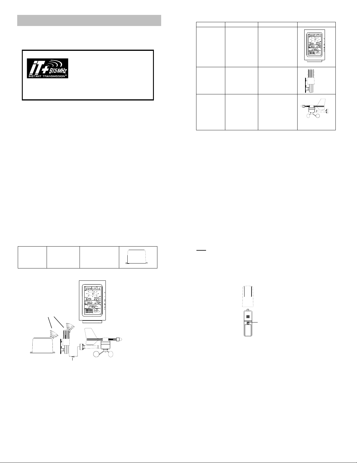
Carefully open and check that the following contents are complete:
Item: Consisting of: Fittings: Illustration:
Base Station
ThermoHygro
Sensor
(TX31U-IT)
Wind Sensor
(TX23U)
1) Main unit
1) Main unit
2) Air Flow
cover
1) Main unit
with wind
vane
2) 32 ft cable
(already
attached the
main unit)
3) Mast holder
1) Wall mounting
screws
2) Plastic anchors
for screws
3) 2 x cable ties
1) 1 x U-bolts for
mast holder
2) 2 x Washers
3) 2 x Nuts
4) 2 x cable ties
2
Rain Sensor
(TX32U-IT)
SETTING UP:
1) Base and
funnel
1) 2 x Screw s
and Plastic
anchors
Wireless transmission
at 915 MHz - thermo-
hygro and rain sensor
to the Weather Ce nter
Rain senso
Cable connection between the wind sensor and the thermo-hygro sensor
3
Weather Center
Wind sensor
Note:
When putting the Weath er Center into operation , i t is important to perform in clos e
proximity (e.g. on a table) a complete wiring and set-up of the system. This step is
important to test all components for correct function before placing and mounting them
at their final destinations (Se e Positioning below). Spin the wind vane and tip the rain
gauge to test.
1. Unwind the cables of the Wind sensor. Connect the Wind sensor to the Thermohygro transmitter by plugging the connector head into the socket of the Thermohygro sensor. The cord should “click” into place.
2. First insert the batteries into the Thermo-hygro sensor and Rain sensor (“How
to install and replace the batteries into the Thermo-hygro sensor“ and
“How to install and replace the batteries into the Rain sensor” below ).
3. Then insert the batteries into the Weather Center (see “How to install and
replace the batteries into the Weather Center” below). Once the batteries are
installed, all segments of the LCD will light up briefly and a short signal tone will
Sockets for wind sensor
4
be heard. It will then display the time as 12:00, the date as 1.1.05, the weather
icons, and air pressure value. "- - -" will be shown for outdoor data.
4. Afterwards, the Weather Center will start receiving data from the transmitter.
The transmission reception icon wi ll be blinking to indicate that the station is
trying to get the thermo-hygro transmitter data. The outdoor temperature,
humidity, wind data should then be displayed on the Weather Center. If this
does not happen after 135 seconds, the batteries will need to be removed from
all units. You will have to start agai n from step 2.
5. The transmitter reception icon is now blinking again to indicate that the station is
trying to get the rain sensor data. It wi ll stop blinking once the rain sensor has
been detected. If this does not happe n a fte r 135 seconds, you will need to start
again from step 2.
6. You may need to check the cable for correct connection and all the components
for correct function by manually turning the wind-gauge by moving the windvane; tilting the rain sensor to hear the impact of the internal moving seesaw,
etc. (see Positioning below).
7. Time and date shall be manually set (See Manual Setting below).
8. After the Weather Center has been checked for correct function with regard to
the above points and found fit, the initial set up of the weather station system is
finished and the mounting of the system components can take place. It must be
ensured however that all compone n ts work properly together at their chosen
mounting or standing locations. If e.g. there appear to be problems with the 915
MHz radio transmission, they can mostly be overcome by slightly changing the
mounting locations or turning the base station.
5
Note:
The radio communication between the receiver and the transmitters in the open field
reaches distances of max 330 feet, provided there are no interfering obstacles such
as buildings, trees, vehicles, high voltage lines, etc.
9. Radio interferences created by PC screens, radios or TV sets can in some
cases entirely cut off radio communication. Please consider this when choosing
standing or mounting locations into consideration when choosing standing or
mounting locations.
Note :
After batteries are installed in the transmitter, insta ll the batteries in the weather
center to receive the signal from the transmitters as soon as possible. If the
weather center is powered more than 5 hours after the transmitter is powered,
the weather center will never rece ive signal successfully from the transmitters.
In this case, user will need to reinstall the batteries from all the transmitters to
redo set-up procedure.
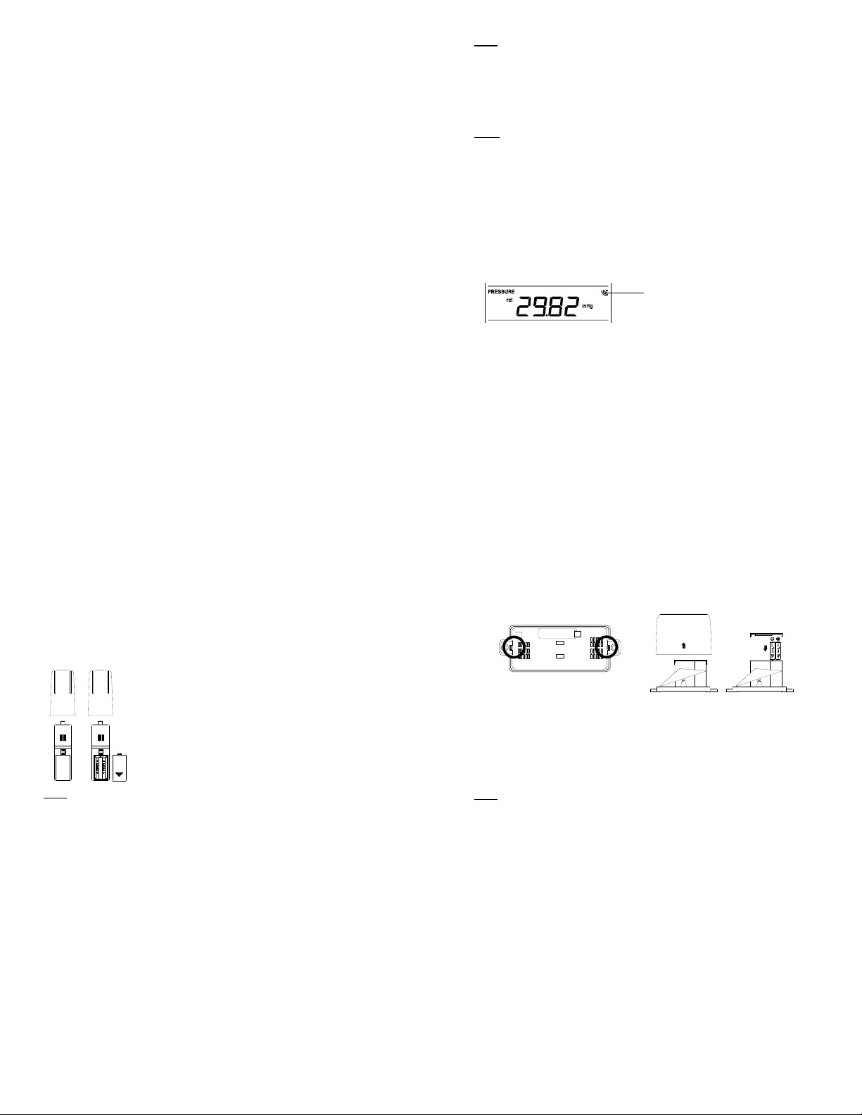
After batteries are installed, there will be synchronization between weather
center and the transmitters. At th is tim e, the sig na l re cept ion i co n will be bl inki ng.
When the signal is successfully received by the weather center, the icon will be
switched on. (If it is not successful, the icon will not be shown in LCD) So the
user can easily see whether the last reception was successful (icon on) or not
(icon off). On the other hand, the short blinking of the icon shows that a
reception is in progress.
Transmitt er si g n al
reception icon
6
If the signal reception is not successful on the firs t frequency (915MHz) for 45
seconds, the frequency is changed to 920MHz and the learning is tried another
45 seconds. If still not successful, the reception is tried for 45 seconds on
910MHz. This will also be done for re-synchronization.
HOW TO INSTALL AND REPLACE THE BATTERIES INTO THE
THERMO-HYGRO SENSOR
Note:
In the event of changing batteries in any of the units, all uni ts need to be reset by
following the setting up procedures. This is because a random security code is
assigned by the thermo-hygro sensor at start-up and this code must be received and
stored by the Weather Center in the first several minutes of power being supplied to it.
The outdoor Thermo-hygro sensor works wit h 2 x AA, IEC
LR6 1.5V Alkaline batteries. To install and replace the
batteries, please follow the steps below:
1. Uninstall the rain cover of the transmitter.
2. Remove the battery compar tment cover.
3. Insert the batteries, observing the correct polarity (see
the marking in the battery compartment).
4. Replace the battery cover.
7
HOW TO INSTALL AND REPLACE THE BATTERIES INTO THE RAIN
SENSOR
Figure 1
The rain sensor works with 2 x AAA, IEC LR3, 1.5V Alkaline batteries. To install and
replace the batteries, please follow the steps below :
1. Press tabs back to unlock rain sensor cover. (Figure 1)
2. Lift rain sensor cover to access battery compartment. (Figure 2)
3. Insert the batteries, observing the correct polarity (see the marking in the battery
compartment). (Figure 3)
4. Replace the battery cover and the rain cover onto the unit.
Note:
In the event of changing batteries in any of the units, all uni ts need to be reset by
following the setting up procedures. This is because a random security code is
assigned by the rain sensor at start-up and this code must be received and stored by
the Weather Center in the first several minutes of power being supplied to it.
Figure 2
Figure 3
8
HOW TO INSTALL AND REPLACE THE BATTERIES INTO THE
A
WEATHER CENTER
The Weather Center works with 3 x AA, IEC LR6, 1.5V
Alkaline batteries. When the batteries need to be replaced,
the low battery symbol will appear on the LCD. To install
and replace the batteries, please follow the steps below:
1. Remove the battery compartment cover.
2. Insert the batteries observing the correct polarity
(see the marking in the battery compartment).
3. Replace the battery cover.
BATTERY CHANGE:
It is recommended to replace the batte ries in all units every 24 months to ensure
optimum accuracy of these units.
Note:
The stored History record will not be kept after the battery change is done on the
Weather Center.
Please participate in the preservation of the environment. Return
used batteries to an authorized depot.
9
FUNCTION KEYS:
Weather Center:
The Weather Center ha s 5 e asy-to-use function keys.
SET
key
+ key
HISTORY key
LARM key
MIN/MAX key
SET key
Press and hold to enter manual setting modes: LCD contrast, Manual time
setting, 12/24 hour time display, Calendar setting, ºF/ ºC temperature unit, Wind
10
speed unit, Rainfall unit, Pressure unit, Relative pressure reference setting,
Weather tendency threshold setting, Storm warning threshold sett ing and Storm
Alarm On/ Off setting
Press to toggle between the display of Mode 1 or Mode 2:
Mode 1: "Wind speed + outdoor temp + rel. pressure"
Mode 2: "Gust + Dew Point temp + rainfall" If pressure is showing with wind
gust, press the plus button to view 24 hour and total rain.
(Mode 2 displayed will be shown for 30 secon ds. Then it will return to normal
display automatically.)
In normal display mode, press and hold to switch on/ off the Buzzer
In the weather alarm setting mode, pres s and hold to adjust different alarm
value and switch the alarm On/ Off
Press to activate the reset mode when max or min record is shown
Stop the alarm during the ti me a larm or weather alarm ringing
+ key
In display Mode 1, press to toggle between the display of Preset alarm time,
date, weekday + date, Indoor temp, or second in the time display
In display mode 2, press to toggle between the display of Rel. Pressure, 24 hour
rainfall and Total rainfall
Press to adjust (increase) the level of different settings
Stop the alarm during the ti me a larm or weather alarm ringing
Press to confirm to reset the max/min record
Press to reset the total rainfal l amount to 0
HISTORY key
Press to display the weather data history records
Stop the alarm during the ti me a larm or weather alarm ringing
11
Press to exit manual setting mode and alarm setting mode
ALARM key
Press to enter the time alarm and weather alarm setting mode
Confirm particular alarm setting
Press to exit the manual se tti ng mode
Stop the alarm during the ti me a larm or weather alarm ringing
Press to exit max/ min record display mode
MIN/MAX key
Press to display minimum and maximum records of various weather data
Press to adjust (decrease) the lev el of different settings
Stop the alarm during the ti me a larm or weather alarm ringing
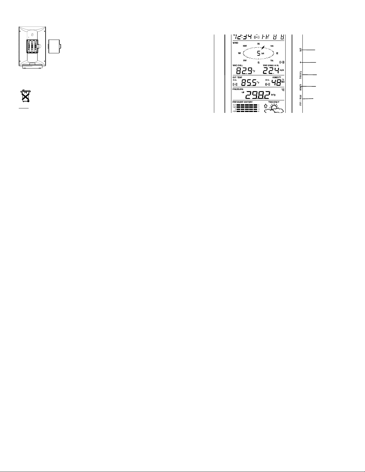
LCD SCREEN
The LCD screen is split into 5 sections displaying the following information:
1. Time and date/ indoor temp/ second
2. Wind data
3. Outdoor temperature, Dew point and humidity,
4. Air pressure, Rainfall data,
5. Air pressure history and Weather forecast icon.
12
 Loading...