

La Crosse Technology TX28U User Manual
TX28U -Wireless 915 MHz Thermo-Hygro Sensor
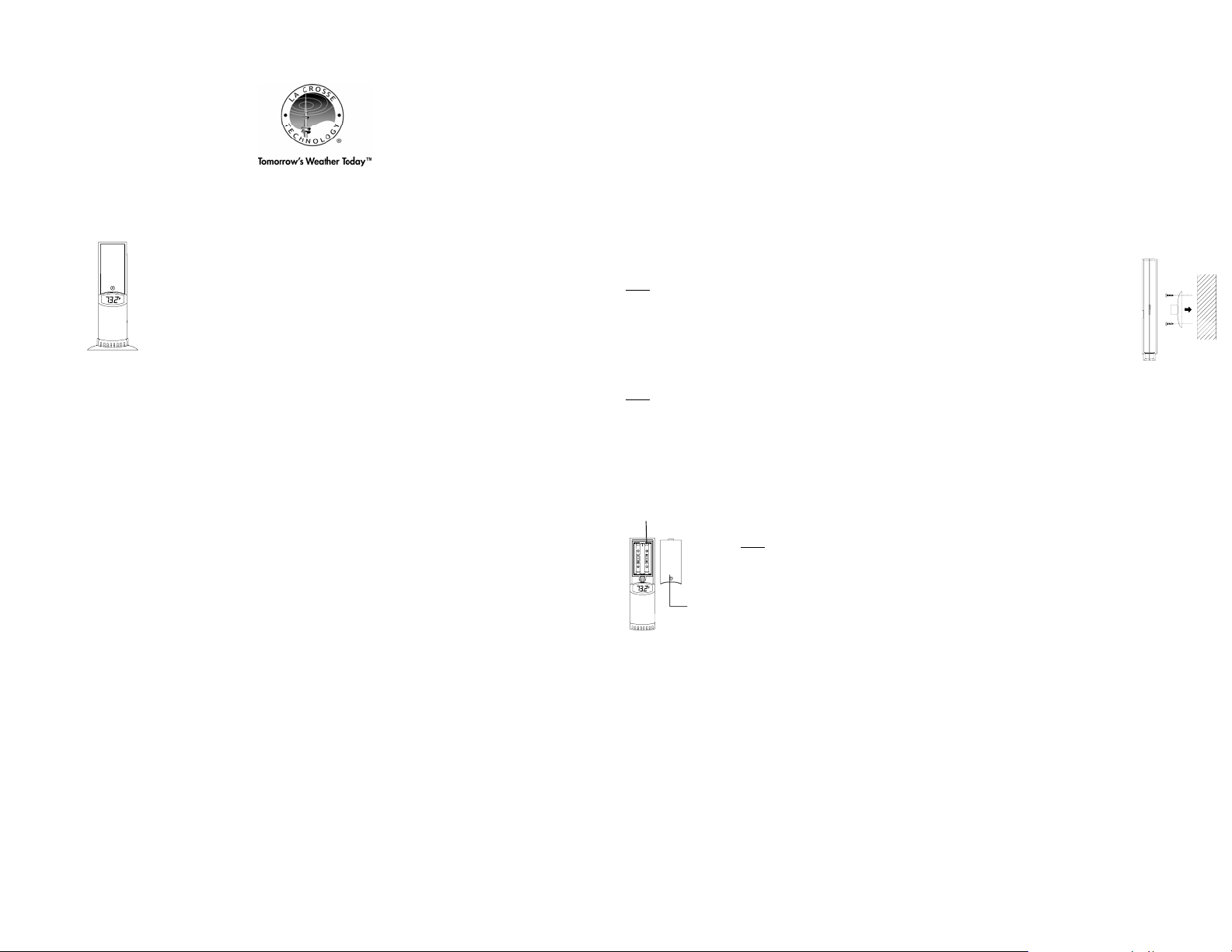
The TX-28U Thermo-Hygro Sensor measures the outdoor temperature and humidity and transfers the data to t he weather station.
Outdoor Thermo-hygro Sensor
• Remote transmission of outdoor temperature and humidity to weather station by 915 MHz
• Displays alternately the measured temperature and humidity readings on LCD
• Water-resistant proof casing
• Wall mounting case
• Mounting at a sheltered place. Avoid direct rain and sunshine
INVENTORY OF CONTENTS
1. One TX28U Thermo-Hygro Sensor
2. Mounting hardware
3. Instruction manual and warranty card.
ADDITIONAL EQUIPMENT (not included)
•
Two fresh AA, IEC LR6, 1.5V Alkaline batteries.
Important Notes on Set-up and Operation
• The Thermo-Hygro Sensor should be placed in a dry, shaded area. Avoid direct sun, as this will cause incorrect readings.
• Fog and mist will not harm your Thermo-Hygro Sensor, but direct rain must be avoided.
• The Thermo-Hygro Sensor has a range of 330 feet (100 m). Keep i n mind that the 330 feet is in open air with no
obstructions and that radio waves DO NOT curve around objects. Actual transmission range will vary depending on what
is in the path of the signal. Each obstruction (roof, walls, floors, ceilings, thick trees, etc.) will effectively cut signal range in
half.
Example: A wireless weather station with a 330 feet (100 m) range is mounted on an interior wall, so that the signal has t o pass
through one interior wall, one exterior wall, and across the 10 feet (3 m) width of the room between the 2 walls. The first wall will
reduce the range to 165 feet (50 m), and the second w all will reduce the range to 87 feet (26.5 m). Factoring in the 10 foot room,
this leaves a maximum of 77 feet (23.5 m) of remaining sign al r ange.
This allowance is typically enough for a frame wall with non-metallic siding; however certain materials can reduce range even
further. Metal siding, stucco, and some types of glass can reduce signal range by as much as ¾ or more, compared to the ½
reduction typical of most obstructions. It is possible to receive a signal through these materials, however maximum range will be
much less due to their tendency to absorb or reflect a much larger portion of the sensor’s signal.
• The Thermo-Hygro Sensor transmits a signal about every 4 seconds. After the batteries have been installed, the weather
station will search for the signal for the duration of few minutes. If there is no temperature reading in the OUTDOOR LCD after
5 minutes, user shall make sure the units are within range of each other, or repeat the battery installation procedure.
• If a button is pressed before weather station receives the signal from the Thermo-Hygro Sensor, you will need to follow the
battery installation procedure again.
SETTING UP:
When one sensor is to be used
1. First, insert the batteries to the Sensor (see “Install and replace batteries in the Thermo-Hygro Sensor” below).
2. Within 2 minutes of powering up the Sensor, insert the batteries to the weather station. Once the batt eries are in place, all
segments of the LCD will light up briefly. Following the indoor temperature and the time as 12:00 will be displayed. If they are
not shown in LCD after 60 seconds, remove the batteries and wait for at least 60 seconds before reinserting them. Once the
indoor data is displayed user may proceed to the next step.
3. After the batteries are inserted, the weather station will start receiving dat a signal from the Sensor. The outdoor temperature
and humidity should then be displayed on the weather stati on. If this does not happen after 2 minutes, the batteries wi ll need
to be removed from both units and reset from step 1.
4. In order to ensure sufficient 915 MHz transmis s ion however, this should under good conditions be a distance no more than
330 feet (100 meters) between the final position of the weather station and the Sensor (see notes on “Positioning” and “915
MHz Reception”).
When more than one sensor is to be used
1. User shall remove all the batteries from the weather station and Sensors and wait 60 seconds if setting has been done with
one Sensor before.
2. Insert the batteries to the first sensor.
3. Within 2 minutes of powering up the first Sensor, insert the batteries to the weather station. Once the batteries are in pla ce,
all segments of the LCD will light up briefly. Following the indoor temperature and t he time as 12:00 will be displayed. If they
are not shown in LCD after 60 seconds, remove the batteries and wait for at least 60 seconds before reinserting them.
4. The outdoor temperature and humidity from the first Sensor (channel 1) should then be displayed on the weather station.
Also, the signal reception icon will be displayed. If this does not happen after 2 minutes, the batteries will need to be
removed from both units and reset from step 1.
5. Insert the batteries to the second sensor as soon as the outd oor temperature and humidity readings from
the first Sensor are displayed on the weather station.
User shall insert the batteries into the second Sensor within 45 seconds of reception of the first Sensor.
Note:
6. The outdoor temperature and humidity from the second Sensor and the "channel 2" icon should then be
displayed on the weather station. If this does not happen aft er 2 minute, the batteries will need to be
removed from all the units and reset from step 1.
7. Insert the batteries to the third Sensor as soon as the "channel 2" icon and outdoor data are displayed on
the weather station. Then within 2 minutes, the channel 3 outdoor data from the third Sensor wi ll be
displayed and the channel icon will shift back to "1" once the third Sensor is successfully received. If this is
not happen, user shall restart the setting up from ste p 1.
User shall insert the batteries into the third Sensor within 45 seconds of reception of the second Sensor.
Note:
8. In order to ensure sufficient 915 MHz transmis s ion however, this should under good conditions be a distance no more than
100 meters between the final position of the weather stati on and the Sensor (see notes on “Positioning” and “915 MHz
Reception”).
INSTALL AND REPLACE BATTERIES IN THE OUTDOOR THERMO-HYGRO SENSOR
The outdoor Thermo-Hygro Sensor uses 2 x AA IEC LR6, 1.5V Alkaline batteries. To install and replace the batteries, please follow
the steps below:
Battery
compartment
Battery
cover
915MHZ SIGNAL RECEPTION
If the outdoor data is not received within three minutes after setting up, the display will show for example , “- - - °F” on th e outdoor
temperature section of the receiver, please check the following points:
1. Distance sensors a t least 2 meters away from any interfering sources such as computer monitors or TV sets.
2. Avoid placing the Thermo-Hygro Sensor onto or in the immediate proximity of metal window frames.
3. Using other electrical products such as headphones or speakers operating on the 915MHz frequency may prevent reception
of the transmitted data. Interference can also be caused by neighbors using similar electrical devices.
POSITIONING THE THERMO-HYGRO SENSOR
1. Remove the battery cover with a small screwdriver.
2. Insert the batteries, observing the correct polarity (see battery compartment marking).
3. Replace the battery cover on the unit.
Note:
•
In the event of changing batteries in any of the units, all units need to be reset by following the
setting up procedures. This is because a random securit y code is assigned by the Sensor at
start-up and this code must be received and stored by the weather station when setting up.
•
Detailed Set up procedures refer to the Instruction Manual of the WS-9020U.

To wall mount:
The Sensor is supplied with a holder that may be attached to a wall with the two screws supplied. The Sensor
can also be position on a flat surface by securing the stand to the bottom to the Sensor.
1. Secure the bracket onto a desired wall using the screws and plastic anchors.
2. Clip the remote Thermo-Hygro Sensor onto the bracket.
Note:
Before permanently fixing the Sensor wall base, place all units in the desired locations to check that t he
outdoor temperature and humidity readings are receivable. In event that the signal is not received,
relocate the Sensors or move them slightly as this may help the signal reception.
CARE AND MAINTENANCE
• Extreme temperatures, vibration and shock should be avoided as these may cause damage to the units and give inaccurate
forecasts and read ings.
• When cleaning the display and casings, use a soft damp cloth only. Do not use solvents or scouring agents as they may mark
the LCD and casings.
• Do not submerge the units in water. Furthermore, fix all parts in place where the unit is adequately protected against moist ure
and rain.
• Immediately remove all low powered batteries to avoid l eak age and damage. Replace only with new batteries of t he
recommended type.
• Do make any repair attempts to the units. Return it to their or iginal point of purchase for repair by a qualified engineer.
Opening and tampering with the units may invalidate their guarantee.
• Do not expose the units to extreme and sudden tem perature changes, this may lead to rapid changes in forecasts and
readings and thereby reduce their accuracy.
SPECIFICATIONS
Detailed Specification refers to Instruction manual of WS-9020U.
Temperature measuring range:
Outdoor : -39.8°F to +139.8°F with 0.2°F resolution/ -39.9ºC to +59.9ºC with 0.1ºC resolution
(“OF.L” displayed if outside this range)
Relative humidity measuring range:
Outdoor : 1% to 99% with 1% resolution
(“1%” displayed when value ≤ 1%; "99%" is displayed if value ≥ 99%)
Outdoor data reception : about every 4.5 seconds
Transmission range : up to 330 feet (100 meters) in open space
Power supply : 2 x AA, IEC LR6, 1.5V
Battery life cycle : approximately 12 months (Alkaline batteries recommended)
Dimensions (L x W x H) : 1.69" x 0.91" x 6.29" (43 x 23 x 160 mm)
WARRANTY INFORMATION
La Crosse Technology, Ltd provides a 1-year limited w arranty on t his pr oduct against manufacturing defects in materials and
workmanship.
This limited warranty begins on the original date of purchase, is valid only on products purchased and us ed in North America and
only to the original purchaser of this product. To receive warranty service, the purchaser must contact La Crosse Technology, Ltd
for problem determination and service procedures. Warranty service can only be performed by a La Crosse Technology , Ltd
authorized service center. The original dated bill of sale must be presented upon request as proof of purchase t o La Crosse
Technology, Ltd or La Crosse Technology, Ltd’s authorized service center.
La Crosse Technology, Ltd will repair or replace this product, at our option and at no charge as stipulated herein, with new or
reconditioned parts or products if found to be defective during the limited warranty period specified above. All replaced parts and
products become the property of La Crosse Technology , Ltd and must be returned to La Crosse Technology, Ltd. Replacement
parts and products assume the remaining original w arranty, or ninety (90) days, whichever is longer. La Crosse Technology, Ltd will
pay all expenses for labor and materials for all repairs covered by this warranty. If necessary repairs are not covered by this
warranty, or if a product is examined which is not in need or re pair, you will be charged for the repairs or examination. The owner
must pay any shipping charges incurred in getting your La Crosse Technology, Ltd product to a La Crosse Technology, Ltd
authorized service center. La Crosse Technology , Ltd will pay ground return shipping charges to the owner of the product to a USA
address only.
Your La Crosse Technology, Ltd warranty covers all defect s in material and workmanship with the following specified exceptions: (1)
damage caused by accident, unreasonable use or neglect (including the lack of reasonable and necessary maintenance); (2)
damage occurring during shipment (claims must be presented to the carrier); (3) damage to, or deterioration of, any accessory or
decorative surface; (4) damage resulting from failure to follow instructions contained in your owner’s manual; (5) damage resulting
from the performance of repairs or alterations by someone other than an authorized La Crosse Technology, Ltd authorized service
center; (6) units used for other than home use (7) applications and uses that this product was not intended or (8) the products
inability to receive a signal due to any source of interference.. This warranty covers only actual defects within the product itself, and
does not cover the cost of installation or removal from a fixed install ation, normal set-up or adjustments, claims based on
misrepresentation by the seller or performance variations resulting from installation-related circumstances.
LA CROSSE TECHNOLOGY, LTD WILL NOT ASSUME LIABILITY FOR INCIDENTAL, CONSEQUENTIAL, PUNITIVE, OR OTHER
SIMILAR DAMAGES ASSOCIATED WITH THE OPERATION OR MALFUNCTION OF THIS PRODUCT. THIS PRODUCT IS NOT
TO BE USED FOR MEDICAL PURPOSES OR FOR PUBLIC INFORMATION. THIS PRODUCT IS NOT A TOY. KEEP OUT OF
CHILDREN’S REACH.
This warranty gives you specific legal rights. You may also have other rights specific to your State. Some States do no allow the
exclusion of consequential or incidental damages therefore the above exclusion of limitation may not ap ply to you.
For warranty work, technical support, or information contact:
All rights reserved. This handbook must not be reproduced in any form, even in excerpts, or duplicated or processed using
electronic, mechanical or chemical procedures without written permission of the publisher.
This handbook may contain mistakes and printing errors. The information in this handbook is regularly checked and corrections
made in the next issue. We accept no liability for technical mistakes or printing errors, or their consequences.
All trademarks and patents are acknowledged.
La Crosse Technology, Ltd
2809 Losey Blvd. S.
La Crosse, WI 54601
Phone: 608.782.1610
Fax: 608.796.1020
support@lacrossetechnology.com
sales@lacrossetechnology.com
(information on other products)
www.lacrossetechnology.com
e-mail:
(warranty work)
web:
 Loading...