

Page 1

FS-C8600DN
FS-C8650DN
SERVICE
MANUAL
Published in June 2012
842MN111
2MNSM061
Rev. 1
Page 2

CAUTION
RISK OF EXPLOSION IF BATTERY IS REPLACED BY AN INCORRECT TYPE. DISPOSE
OF USED BATTERIES ACCORDING TO THE INSTRUCTIONS.
It may be illegal to dispose of this battery into the municipal waste stream. Check with your
local solid waste officials for details in your area for proper disposal.
ATTENTION
IL Y A UN RISQUE D’EXPLOSION SI LA BATTERIE EST REMPLACEE PAR UN MODELE
DE TYPE INCORRECT. METTRE AU REBUT LES BATTERIES UTILISEES SELON LES
INSTRUCTIONS DONNEES.
Il peut être illégal de jeter les batteries dans des eaux d’égout municipales. Vérifiez avec les
fonctionnaires municipaux de votre région pour les détails concernant des déchets solides
et une mise au rebut appropriée.
Notation of products in the manual
For the purpose of this service manual, products are identified by print speed at A4 and
black and white modes.
FS-C8600DN: 45 ppm model
FS-C8650DN: 55 ppm model
Page 3

Revision history
Revision Date Replaced pages Remarks
1 June 18, 2012 Contents, 1-1-1 to 1-1-3,1-1-6,1-2-2,1-2-8,1-2-9,
1-2-19,1-2-20,1-2-22,1-2-26,1-2-28,1-3-32,1-2-33,
1-2-38,1-2-43,1-3-6 to 1-3-8,1-3-10,1-3-16,1-3-17,
1-3-21 to 1-3-23,1-3-26 to 1-3-29,1-3-31 to 1-3-34,
1-3-37,1-3-38,1-3-48,1-3-49,1-3-53,1-3-54,1-3-59,
1-3-60,1-3-62,1-3-65,1-3-72,1-3-76,1-3-77,1-3-79,
1-3-84,1-3-85,1-3-87 to 1-3-91,1-3-93 to 1-3-96,
1-3-99,1-3-106,1-3-108,1-3-112 to 1-3-116,1-3-126,
1-3-130 to 1-3-133,1-3-135,1-3-137,1-3-139,
1-3-141,1-3-147 to1-3-150,1-4-2,1-4-26 to 1-4-28,
1-4-35 to 1-4-39,1-4-42,1-4-55,1-4-58 to 1-4-60,
1-4-71,1-4-88,1-4-90,1-4-91,1-5-1,1-5-4,1-5-8,
1-5-11,1-5-17,1-5-18,1-5-24,1-5-26,1-5-32,1-5-44 to
1-5-46,1-5-48,1-5-49,1-5-54,1-5-79 to 1-5-81,1-6-1,
1-6-2,2-2-1,2-2-3,2-3-1,2-3-8,2-3-28,2-3-32,2-3-36,
2-3-46,2-3-56,2-3-62,2-3-68,2-3-72,2-4-3,2-4-7,
2-4-8,2-4-13,2-4-22,2-4-23
Page 4

This page is intentionally left blank.
Page 5

Safety precautions
This booklet provides safety warnings and precautions for our service personnel to ensure the safety of
their customers, their machines as well as themselves during maintenance activities. Service personnel
are advised to read this booklet carefully to familiarize themselves with the warnings and precautions
described here before engaging in maintenance activities.
Page 6
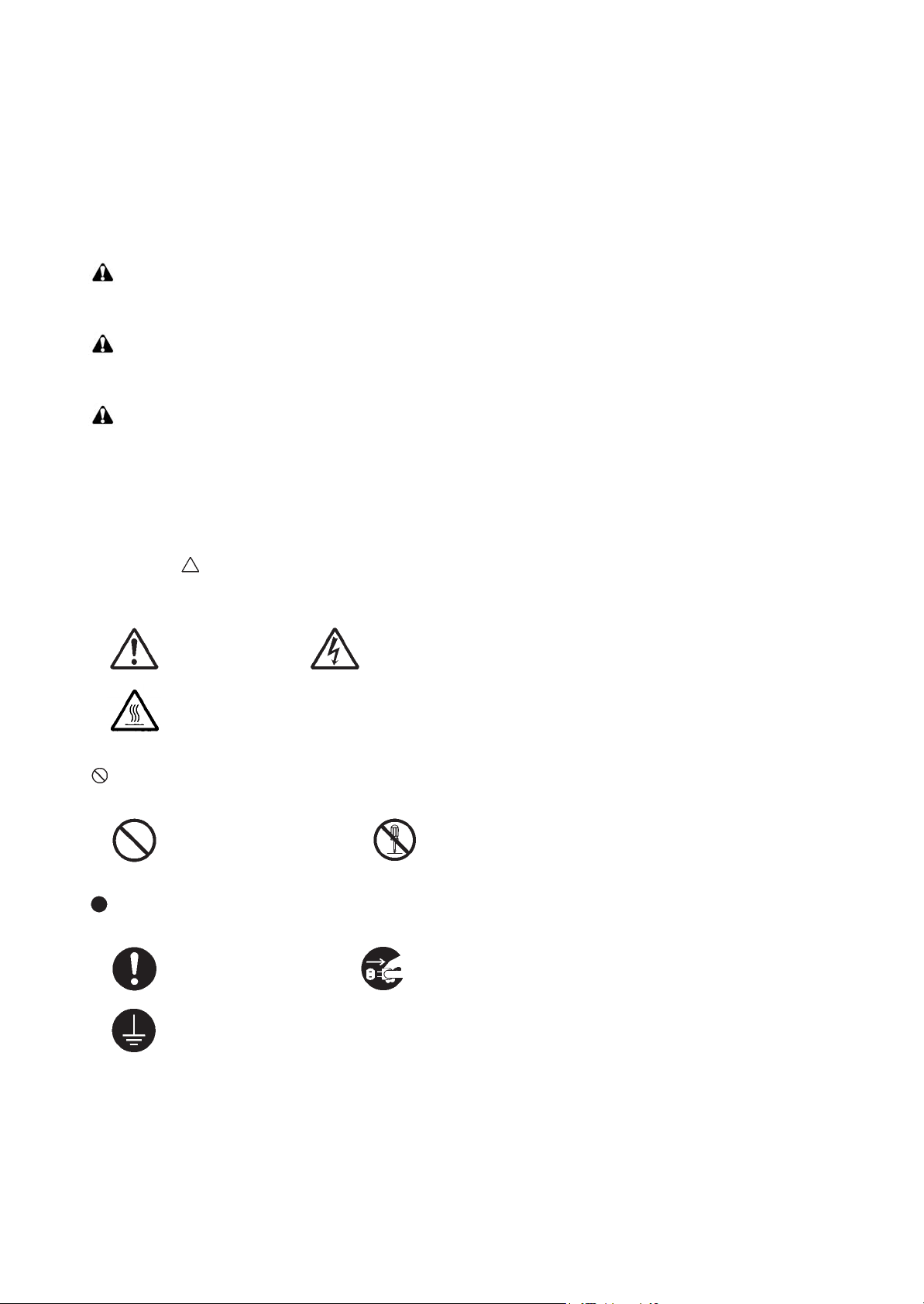
Safety warnings and precautions
Various symbols are used to protect our service personnel and customers from physical danger and
to prevent damage to their property. These symbols are described below:
DANGER: High risk of serious bodily injury or death may result from insufficient attention to or incorrect
compliance with warning messages using this symbol.
WARNING: Serious bodily injury or death may result from insufficient attention to or incorrect compliance
with warning messages using this symbol.
CAUTION: Bodily injury or damage to property may result from insufficient attention to or incorrect com-
pliance with warning messages using this symbol.
Symbols
The triangle ( ) symbol indicates a warning including danger and caution. The specific point of attention is
shown inside the symbol.
General warning. Warning of risk of electric shock.
Warning of high temperature.
indicates a prohibited action. The specific prohibition is shown inside the symbol.
General prohibited action. Disassembly prohibited.
indicates that action is required. The specific action required is shown inside the symbol.
General action required. Remove the power plug from the wall outlet.
Always ground the machine.
Page 7

1. Installation Precautions
WARNING
• Do not use a power supply with a voltage other than that specified. Avoid multiple connections to
one outlet: they may cause fire or electric shock. When using an extension cable, always check that
it is adequate for the rated current. .....................................................................................................
• Connect the ground wire to a suitable grounding point. Not grounding the machine may cause fire
or electric shock. Connecting the earth wire to an object not approved for the purpose may cause
explosion or electric shock. Never connect the ground cable to any of the following: gas pipes, lightning rods, ground cables for telephone lines and water pipes or faucets not approved by the proper
authorities. ..........................................................................................................................................
CAUTION:
• Do not place the machine on an infirm or angled surface: the machine may tip over, causing injury. .
• Do not install the machine in a humid or dusty place. This may cause fire or electric shock. ..............
• Do not install the machine near a radiator, heater, other heat source or near flammable material.
This may cause fire............................................................................................................................
• Allow sufficient space around the machine to allow the ventilation grills to keep the machine as
cool as possible. Insufficient ventilation may cause heat buildup and poor printing performance. .....
• Always handle the machine by the correct locations when moving it. .................................................
• Always use anti-toppling and locking devices on machines so equipped. Failure to do this may
cause the machine to move unexpectedly or topple, leading to injury. ...............................................
• Avoid inhaling toner or developer excessively. Protect the eyes. If toner or developer is accidentally
ingested, drink a lot of water to dilute it in the stomach and obtain medical attention immediately.
If it gets into the eyes, rinse immediately with copious amounts of water and obtain medical atten-
tion. .....................................................................................................................................................
• Advice customers that they must always follow the safety warnings and precautions in the
machine’s instruction handbook. .......................................................................................................
Page 8
2. Precautions for Maintenance
WARNING
• Always remove the power plug from the wall outlet before starting machine disassembly. ................
• Always follow the procedures for maintenance described in the service manual and other related
brochures. ..........................................................................................................................................
• Under no circumstances attempt to bypass or disable safety features including safety mechanisms
and protective circuits. ........................................................................................................................
• Always use parts having the correct specifications. ............................................................................
• Always use the thermostat or thermal fuse specified in the service manual or other related brochure
when replacing them. Using a piece of wire, for example, could lead to fire or other serious acci-
dent. ...................................................................................................................................................
• When the service manual or other serious brochure specifies a distance or gap for installation of a
part, always use the correct scale and measure carefully. ..................................................................
• Always check that the machine is correctly connected to an outlet with a ground connection. ...........
• Check that the power cable covering is free of damage. Check that the power plug is dust-free. If it
is dirty, clean it to remove the risk of fire or electric shock. .................................................................
• Never attempt to disassemble the optical unit in machines using lasers. Leaking laser light may
damage eyesight. ...............................................................................................................................
• Handle the charger sections with care. They are charged to high potentials and may cause electric
shock if handled improperly. ...............................................................................................................
CAUTION
• Wear safe clothing. If wearing loose clothing or accessories such as ties, make sure they are safely
secured so they will not be caught in rotating sections. ......................................................................
• Use utmost caution when working on a powered machine. Keep away from chains and belts. ..........
• Handle the fixing section with care to avoid burns as it can be extremely hot. ..................................
• Check that the fixing unit thermistor, heat and press rollers are clean. Dirt on them can cause
abnormally high temperatures. ...........................................................................................................
Page 9

• Do not remove the ozone filter, if any, from the machine except for routine replacement. .................
• Do not pull on the AC power cord or connector wires on high-voltage components when removing
them; always hold the plug itself. ........................................................................................................
• Do not route the power cable where it may be stood on or trapped. If necessary, protect it with a
cable cover or other appropriate item. ................................................................................................
• Treat the ends of the wire carefully when installing a new charger wire to avoid electric leaks. ..........
• Remove toner completely from electronic components. .....................................................................
• Run wire harnesses carefully so that wires will not be trapped or damaged. ......................................
• After maintenance, always check that all the parts, screws, connectors and wires that were
removed, have been refitted correctly. Special attention should be paid to any forgotten connector,
trapped wire and missing screws. .......................................................................................................
• Check that all the caution labels that should be present on the machine according to the instruction
handbook are clean and not peeling. Replace with new ones if necessary. .......................................
• Handle greases and solvents with care by following the instructions below: ......................................
· Use only a small amount of solvent at a time, being careful not to spill. Wipe spills off completely.
· Ventilate the room well while using grease or solvents.
· Allow applied solvents to evaporate completely before refitting the covers or turning the power
switch on.
· Always wash hands afterwards.
• Never dispose of toner or toner bottles in fire. Toner may cause sparks when exposed directly to
fire in a furnace, etc. ...........................................................................................................................
• Should smoke be seen coming from the machine, remove the power plug from the wall outlet
immediately. .......................................................................................................................................
3. Miscellaneous
WARNING
• Never attempt to heat the drum or expose it to any organic solvents such as alcohol, other than the
specified refiner; it may generate toxic gas. ........................................................................................
• Keep the machine away from flammable liquids, gases, and aerosols. A fire or an electric shock
might occur. ........................................................................................................................................
Page 10

This page is intentionally left blank.
Page 11

CONTENTS
1-1 Specifications
1-1-1 Specifications ........................................................................................................................ 1-1-1
1-1-2 Parts names .......................................................................................................................... 1-1-4
(1) Machine ............................................................................................................................ 1-1-4
(2) Option ............................................................................................................................... 1-1-6
(3) Operation panel ................................................................................................................ 1-1-7
1-1-3 Machine cross section ........................................................................................................... 1-1-8
1-2 Installation
1-2-1 Installation environment......................................................................................................... 1-2-1
1-2-2 Unpacking and installation..................................................................................................... 1-2-2
(1) Installation procedure .......................................................................................................1-2-2
(2) Shut-down ......................................................................................................................1-2-19
(3) Setting initial print modes ............................................................................................... 1-2-20
1-2-3 Installing the cassette heater (option).................................................................................. 1-2-21
1-2-4 Installing the gigabit ethernet board (option) ....................................................................... 1-2-26
1-2-5 Installing the IC card reader holder (option) ........................................................................ 1-2-28
1-2-6 Installing the duct unit (option)............................................................................................. 1-2-43
2MN/2N1-1
1-3 Maintenance Mode
1-3-1 Maintenance mode ................................................................................................................ 1-3-1
(1) Executing a maintenance item ......................................................................................... 1-3-1
(2) Maintenance modes item list ............................................................................................ 1-3-2
1-4 Troubleshooting
1-4-1 Paper misfeed detection ........................................................................................................ 1-4-1
(1) Paper misfeed indication .................................................................................................. 1-4-1
(2) Paper misfeed detection condition ................................................................................... 1-4-2
1-4-2 Self-diagnostic function ....................................................................................................... 1-4-26
(1) Self-diagnostic function .................................................................................................. 1-4-26
(2) Self diagnostic codes...................................................................................................... 1-4-27
1-4-3 Image formation problems ................................................................................................... 1-4-86
(1) No image appears (entirely white).................................................................................. 1-4-87
(2) No image appears (entirely black).................................................................................. 1-4-87
(3) Image is too light. ........................................................................................................... 1-4-88
(4) The background is colored. ............................................................................................ 1-4-88
(5) White streaks are printed vertically................................................................................. 1-4-89
(6) Black streaks are printed vertically. ................................................................................ 1-4-89
(7) Streaks are printed horizontally. ..................................................................................... 1-4-89
(8) Spots are printed. ...........................................................................................................1-4-90
(9) Image is blurred.............................................................................................................. 1-4-90
(10) The leading edge of the image is consistently misaligned with the original. ..................1-4-90
(11) The leading edge of the image is sporadically misaligned with the original. ..................1-4-90
(12) Paper is wrinkled. ...........................................................................................................1-4-91
(13) Offset occurs. .................................................................................................................1-4-91
(14) Part of image is missing. ................................................................................................ 1-4-91
(15) Fusing is loose................................................................................................................ 1-4-92
(16) Image is out of focus. ..................................................................................................... 1-4-92
(17) Image center does not align with the original center. ..................................................... 1-4-92
Page 12

(18) Unevenly repeating horizontal streaks in the printed objects.
Colored spots in the printed objects. .............................................................................. 1-4-92
1-4-4 Electric problems ................................................................................................................. 1-4-93
1-4-5 Mechanical problems........................................................................................................... 1-4-98
1-5 Assembly and disassembly
1-5-1 Precautions for assembly and disassembly........................................................................... 1-5-1
(1) Precautions....................................................................................................................... 1-5-1
(2) Drum................................................................................................................................. 1-5-1
(3) Toner ................................................................................................................................ 1-5-1
(4) How to tell a genuine Kyocera toner container................................................................. 1-5-2
1-5-2 Paper feed section................................................................................................................. 1-5-3
(1) Detaching and refitting the primary paper feed unit.......................................................... 1-5-3
(2) Detaching and refitting the forwarding pulley, paper feed pulley and separation pulley... 1-5-7
(3) Detaching and refitting the MP tray paper feed unit ......................................................... 1-5-8
(4) Detaching and refitting the MP forwarding pulley,
MP paper feed pulley and MP separation pulley ............................................................ 1-5-12
1-5-3 Optical section ..................................................................................................................... 1-5-17
(1) Detaching and refitting the LSU...................................................................................... 1-5-17
(2) Color registration adjustment.......................................................................................... 1-5-24
1-5-4 Image formation section ...................................................................................................... 1-5-27
(1) Detaching and refitting the inner unit.............................................................................. 1-5-27
(2) Detaching and refitting the developer unit and drum unit ............................................... 1-5-29
(3) Detaching and refitting the charger roller unit................................................................. 1-5-31
1-5-5 Transfer section ................................................................................................................... 1-5-32
(1) Detaching and refitting the paper conveying unit ........................................................... 1-5-32
(2) Detaching and refitting the transfer belt unit................................................................... 1-5-34
(3) Detaching and refitting the cleaning pre brush ............................................................... 1-5-36
(4) Detaching and refitting the transfer roller ....................................................................... 1-5-38
1-5-6 Fuser section ....................................................................................................................... 1-5-40
(1) Detaching and refitting the fuser unit.............................................................................. 1-5-40
(2) Detaching and refitting fuser IH unit ............................................................................... 1-5-42
1-5-7 PWBs................................................................................................................................... 1-5-44
(1) Detaching and refitting the main PWB............................................................................ 1-5-44
(2) Detaching and refitting the engine PWB......................................................................... 1-5-49
(3) Detaching and refitting the power source PWB.............................................................. 1-5-51
(4) Detaching and refitting the high voltage PWB 1 ............................................................. 1-5-54
(5) Detaching and refitting the high voltage PWB 2 ............................................................. 1-5-55
(6) Detaching and refitting the fuser IH PWB....................................................................... 1-5-56
1-5-8 Drive section........................................................................................................................ 1-5-61
(1) Detaching and refitting the drum drive unit K and the drum drive unit MCY................... 1-5-61
(2) Detaching and refitting the main drive unit ..................................................................... 1-5-64
(3) Detaching and refitting the fuser drive unit, transfer drive unit and feed drive unit.........1-5-65
(4) Detaching and refitting the lift motor 1 and 2.................................................................. 1-5-71
1-5-9 Others .................................................................................................................................. 1-5-72
(1) Detaching the eject filter ................................................................................................. 1-5-72
(2) Detaching and refitting the toner filter............................................................................. 1-5-73
(3) Detaching and refitting the fan filter................................................................................ 1-5-74
(4) Detaching and refitting the transfer belt filter.................................................................. 1-5-75
(5) Detaching and refitting the left filter ................................................................................ 1-5-76
(6) Detaching and refitting the developer filter ..................................................................... 1-5-77
(7) Detaching and refitting the hard disk unit ....................................................................... 1-5-78
(8) Detaching and refitting the eject unit .............................................................................. 1-5-80
2MN/2N1-1
Page 13

(9) Direction of installing the principal fan motors ................................................................ 1-5-81
1-6 Requirements on PWB Replacement
1-6-1 Upgrading the firmware ......................................................................................................... 1-6-1
1-6-2 Remarks on main PWB replacement..................................................................................... 1-6-2
1-6-3 Remarks on engine PWB replacement ................................................................................. 1-6-4
2-1 Mechanical Construction
2-1-1 Paper feed/conveying section ............................................................................................... 2-1-1
(1) Cassette paper feed section............................................................................................. 2-1-1
(2) MP tray paper feed section............................................................................................... 2-1-3
(3) Paper conveying section .................................................................................................. 2-1-5
2-1-2 Drum section ......................................................................................................................... 2-1-7
2-1-3 Developer section .................................................................................................................. 2-1-9
2-1-4 Laser scanner section ......................................................................................................... 2-1-11
2-1-5 Transfer/Separation section ................................................................................................2-1-13
(1) Intermediate transfer unit section ................................................................................... 2-1-13
(2) Secondary transfer roller section.................................................................................... 2-1-15
2-1-6 Fuser section ....................................................................................................................... 2-1-17
2-1-7 Eject/Feedshift section ........................................................................................................ 2-1-19
2-1-8 Duplex conveying section.................................................................................................... 2-1-21
2MN/2N1
2-2 Electrical Parts Layout
2-2-1 Electrical parts layout ............................................................................................................ 2-2-1
(1) PWBs................................................................................................................................ 2-2-1
(2) Switches and sensors....................................................................................................... 2-2-4
(3) Motors............................................................................................................................... 2-2-6
(4) Fan motors ....................................................................................................................... 2-2-8
(5) Others............................................................................................................................. 2-2-10
2-3 Operation of the PWBs
2-3-1 Main PWB.............................................................................................................................. 2-3-1
2-3-2 Engine PWB .......................................................................................................................... 2-3-8
2-3-3 Power source PWB ............................................................................................................. 2-3-32
2-3-4 Front PWB ........................................................................................................................... 2-3-36
2-3-5 Feed PWB 1 ........................................................................................................................ 2-3-46
2-3-6 Feed PWB 2 ........................................................................................................................ 2-3-56
2-3-7 Relay PWB .......................................................................................................................... 2-3-62
2-3-8 Motor control PWB .............................................................................................................. 2-3-68
2-3-9 LSU relay PWB.................................................................................................................... 2-3-72
2-4 Appendixes
2-4-1 Appendixes ............................................................................................................................ 2-4-1
(1) List of maintenance parts ................................................................................................. 2-4-1
(2) Maintenance kits............................................................................................................... 2-4-2
(3) Periodic maintenance procedures .................................................................................... 2-4-3
(4) Repetitive defects gauge .................................................................................................. 2-4-7
(5) Firmware environment commands ................................................................................... 2-4-8
(6) Wiring diagram ............................................................................................................... 2-4-15
Page 14

2MN/2N1
This page is intentionally left blank.
Page 15

1-1 Specifications
1-1-1 Specifications
Machine
2MN/2N1-1
Item
Specifications
45 ppm 55 ppm
Type Desktop
Printing method Electrophotography by semiconductor laser, tandem drum system
Paper weight
Cassette 60 to 256 g/m
MP tray 60 to 300 g/m
2
2
Plain, Rough, Vellum, Recycled, Preprinted, Bond, Color (Colour),
Cassette
Prepunched, Letterhead, Thick, High Quality, Custom 1 to 8
(Duplex: Same as simplex)
Paper type
Plain, Transparency (OHP film), Rough, Vellum, Labels, Recycled,
MP tray
Preprinted, Bond, Cardstock, Color (Colour), Prepunched, Letterhead,
Thick, Coated, Envelope, High Quality, Custom 1 to 8
Cassette
A3, B4, A4, A4R, B5, B5R, A5R, Ledger, Legal, Letter, LetterR,
StatementR, Oficio II, 12 × 18", Folio, 8K, 16K, 16KR
A3, B4, A4, A4R, B5, ISO B5, B5R, A5R, B6R, A6R, Return postcard,
Paper size
MP tray
Postcards, Envelope DL, Envelope C5, Envelope C4, Envelope #10
(Commercial #10), Envelope #9 (Commercial #9), Envelope #6
(Commercial #6 3/4), Envelope Monarch, Youkei 2, Youkei 4, Ledger,
Legal, Letter, LetterR, Executive, StatementR, Oficio II, 12 × 18", Folio,
8K, 16K, 16KR, Custom (98× 148mm × 304.9 × 1219.2mm)
Printing
speed
First print
time
(A4, feed from
cassette)
B/W
Color
B/W
Color
A4 : 45 ppm
Letter : 45 ppm
A4R : 24 ppm
LetterR : 24 ppm
A3 : 22 ppm
Ledger : 22 ppm
B4 : 27 ppm
Legal : 21 ppm
B5 : 45 ppm
A4 : 45 ppm
Letter : 45 ppm
A4R : 24 ppm
LetterR : 24 ppm
A3 : 22 ppm
Ledger : 22 ppm
B4 : 27 ppm
Legal : 21 ppm
B5 : 45 ppm
5.4 s or less
6.6 s or less
A4 : 55 ppm
Letter : 55 ppm
A4R : 24 ppm
LetterR : 24 ppm
A3 : 27 ppm
Ledger : 27 ppm
B4 : 33 ppm
Legal : 21 ppm
B5 : 55 ppm
A4 : 50 ppm
Letter : 50 ppm
A4R : 24 ppm
LetterR : 24 ppm
A3 : 25 ppm
Ledger : 25 ppm
B4 : 30 ppm
Legal : 21 ppm
B5 : 50 ppm
4.9 s or less
6.2 s or less
1-1-1
Page 16

2MN/2N1-1
Item
45 ppm 55 ppm
Warm-up
time
(22 °C/71.6
°F, 60% RH)
Paper
capacity
Power on 41 s or less
Low Power 25 s or less
Sleep
Cassette
41 s or less
550 sheets (64 g/m
500 sheets (80 g/m
A4/Letter or less
MP tray
165 sheets (64 g/m
More than A4/Letter
55 sheets (64 g/m
Main tray 500 sheets (80 g/m
Output tray
capacity
Job separa-
tor tray
250 sheets (80 g/m
(When the Documents Finisher is installed, 100 sheets.)
Photoconductor a-Si (drum diameter 30 mm)
Image write system Semiconductor laser
Charging system Charger roller
Touch down developing system
Developing system
Developer: 2-component
Toner replenishing: Automatic from the toner container
Specifications
2
)
2
)
2
) 150 sheets (80 g/m2)
2
) 50 sheets (80 g/m2)
2
)
2
)
45 s or less
25 s or less
45 s or less
Transfer system
Primary: Roller transfer system (Intermediate transfer belt)
Secondary:Roller transfer system
Separation system Small diameter separation, Separation electrode
Cleaning system
Drum: Counter blade, Cleaning roller
Transfer belt: Fur brush
Charge erasing system Exposure by cleaning lamp (LED)
Belt fusing
Fusing system
Heat source: IH
Abnormally high temperature protection devices: thermostat
CPU PowerPC 750GL/750 MHz
Main
memory
Standard 1024 MB (1024 MB DIMMx 1)
Maximum 2048 MB(1024 MB DIMMx 2)
Hard Disk 160 GB (160 GB x 1) (standard)
USB Interface Connector: 1 (Hi-Speed USB)
Interface
Standard
Option
USB Port: 2 (Hi-Speed USB)
Network interface: 1 (10 BASE-T/100 BASE-TX/1000 BASE-T)
Network interface: 1 (10 BASE-T/100 BASE-TX/1000 BASE-T)
Resolution 600 × 600 dpi
Operating system
Windows XP, Windows Server 2003, Windows Vista, Windows 7, Windows
Server 2008, Apple Macintosh OS 10.x
Page description language PRESCRIBE
1-1-2
Page 17

2MN/2N1-1
Operating
environment
Dimensions
(W × D × H)
Space
required (W
× D)
Weight 111 kg / 244.7 lb
Power source
Item
Temperature 10 to 32.5 °C/50 to 90.5 °F
Humidity 15 to 80% RH
Altitude 2,500 m/8,202 ft or less
Brightness 1,500 lux or less
machine
only
machine
with Paper
feeder
Using
MP tray
FUll system
672 × 787 × 744 mm
26 29/64 × 30 63/64 × 29 13/32”
672 × 787 ×1053 mm
26 29/64 × 30 63/64 × 41 19/64”
1001 × 787 mm
39 13/32 × 30 63/64
1937 × 787 mm (machine + 4000-sheet finisher + Side deck)
76 17/64 × 30 63/64”
120 V AC, 60 Hz, more than 12.0 A
220 - 240 V AC, 50/60 Hz, more than 7.2 A
45 ppm 55 ppm
Specifications
Paper feeder, Large capacity feeder, Side deck, Side multi tray, Side paper
Options
NOTE: These specifications are subject to change without notice.
feeder, Side large capacity feeder, 1000-sheet finisher, 4000-sheet finisher,
Center-folding unit, Mailbox, Punch unit, Data security kit,Emulation option
kit, Gigabit ethernet board, IC card reader holder and Duct unit
1-1-3
Page 18
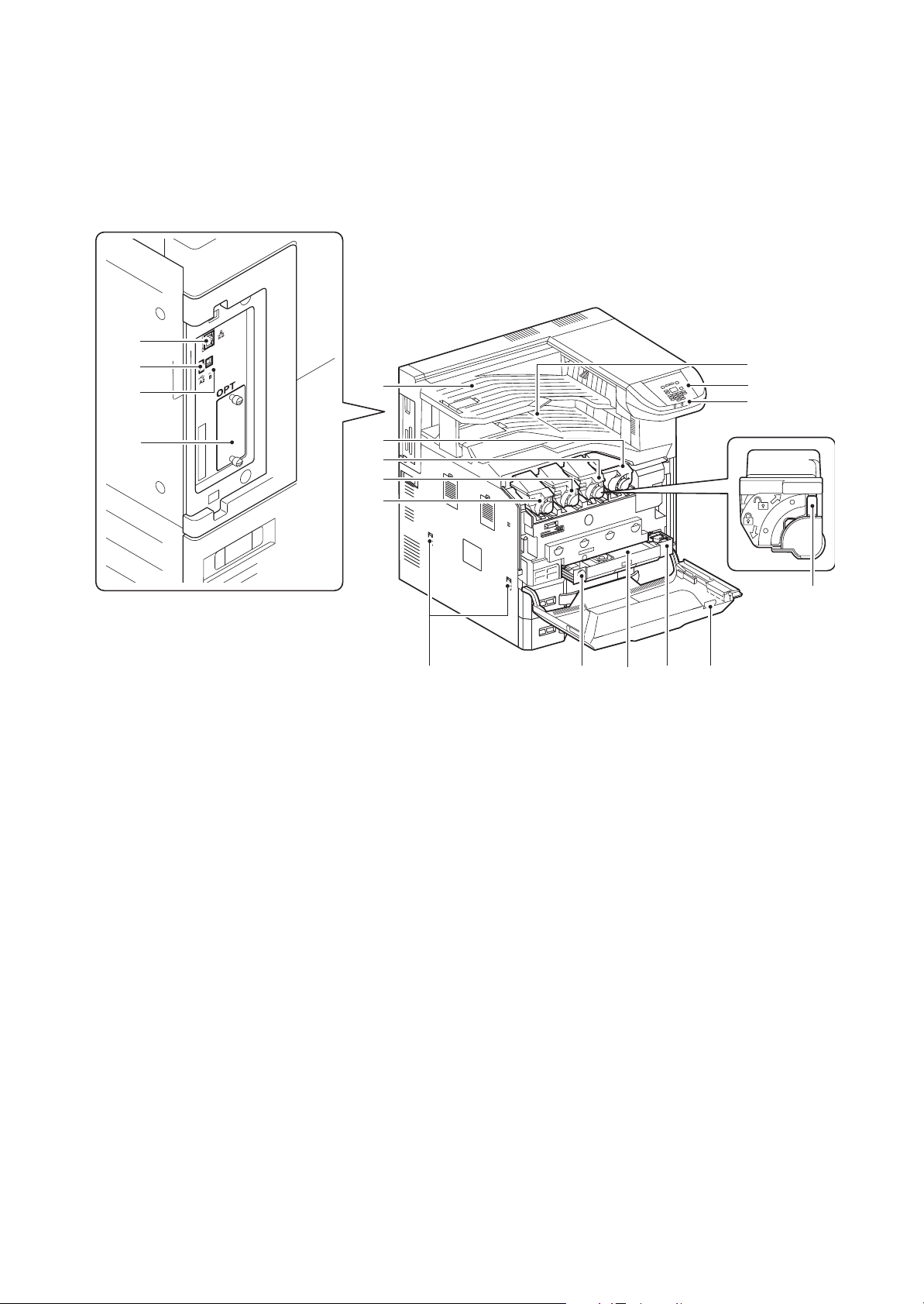
1-1-2 Parts names
7
8
18
13 10 11
3
4
5
6
1
2
15
16
17
14
12
9
1. Operation panel
2. Indicators
3. Main tray
4. Job separator tray
5. Toner container K
6. Toner container M
7. Toner container C
8. Toner container Y
9. Release button
10. Waste toner box
11. Waste toner tray
12. Front cover
13. Handles
14. Network interface connector
15. USB port
16. USB interface connector
17. Option interface
18. Toner container release lever
(1) Machine
2MN/2N1
Figure 1-1-1
1-1-4
Page 19
2MN/2N1
36
25
22 23
26
33
35
19
30
32
34
27
29
24 24
20 21
31
28
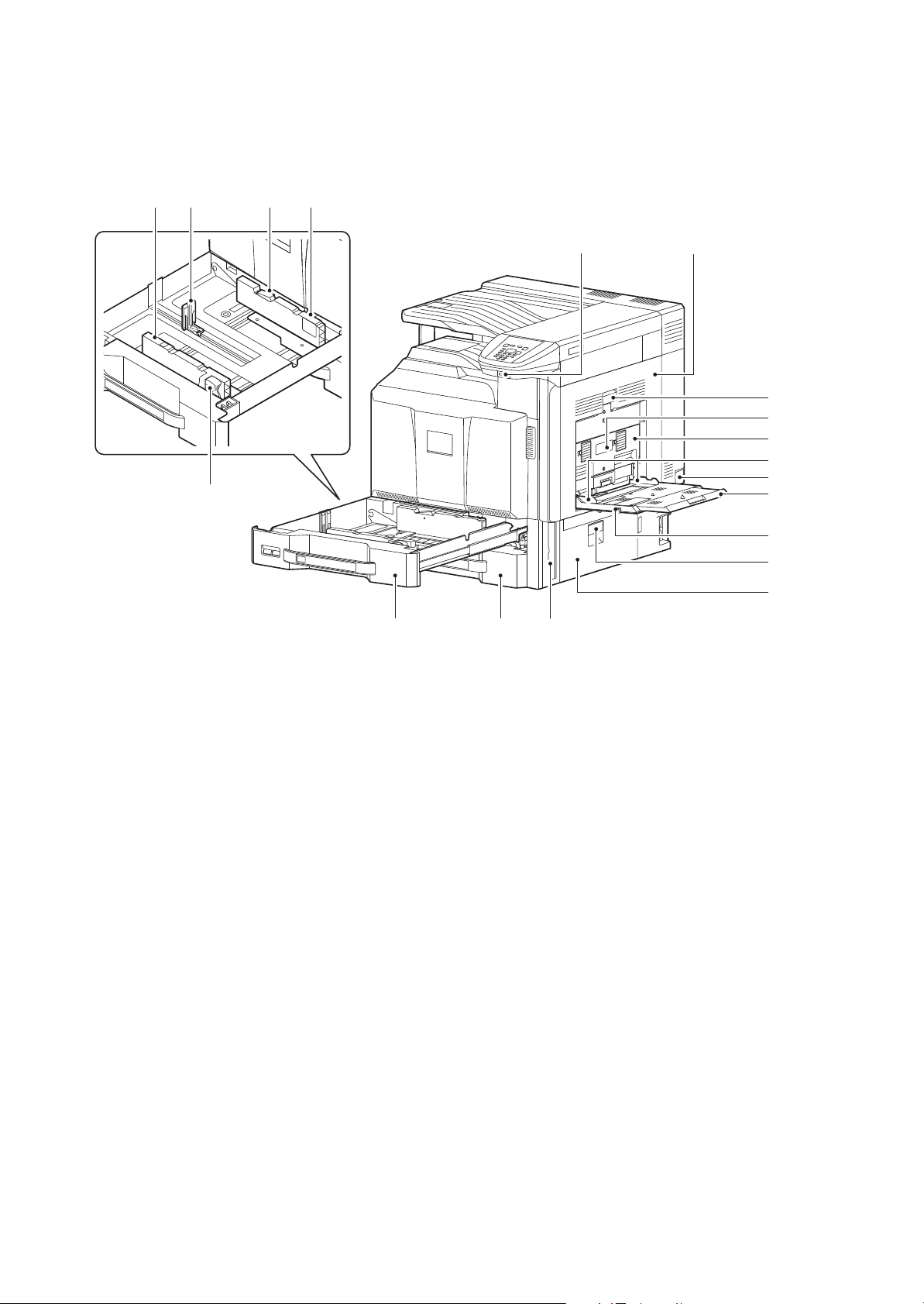
19. USB port
20. Cassettes 1
21. Cassettes 2
22. Paper length guide
23. Guide lock lever
24. Paper width guide
25. Paper width adjusting tab
26. Paper conveying unit
27. Paper conveying unit lever
28. Duplex cover lever
29. Duplex cover
30. MP paper width guide
31. Main power switch
32. MP support Tray
33. MP (Multi-Purpose) tray
34. Paper conveying cover lever
35. Paper conveying cover
36. Handle
Figure 1-1-2
1-1-5
Page 20
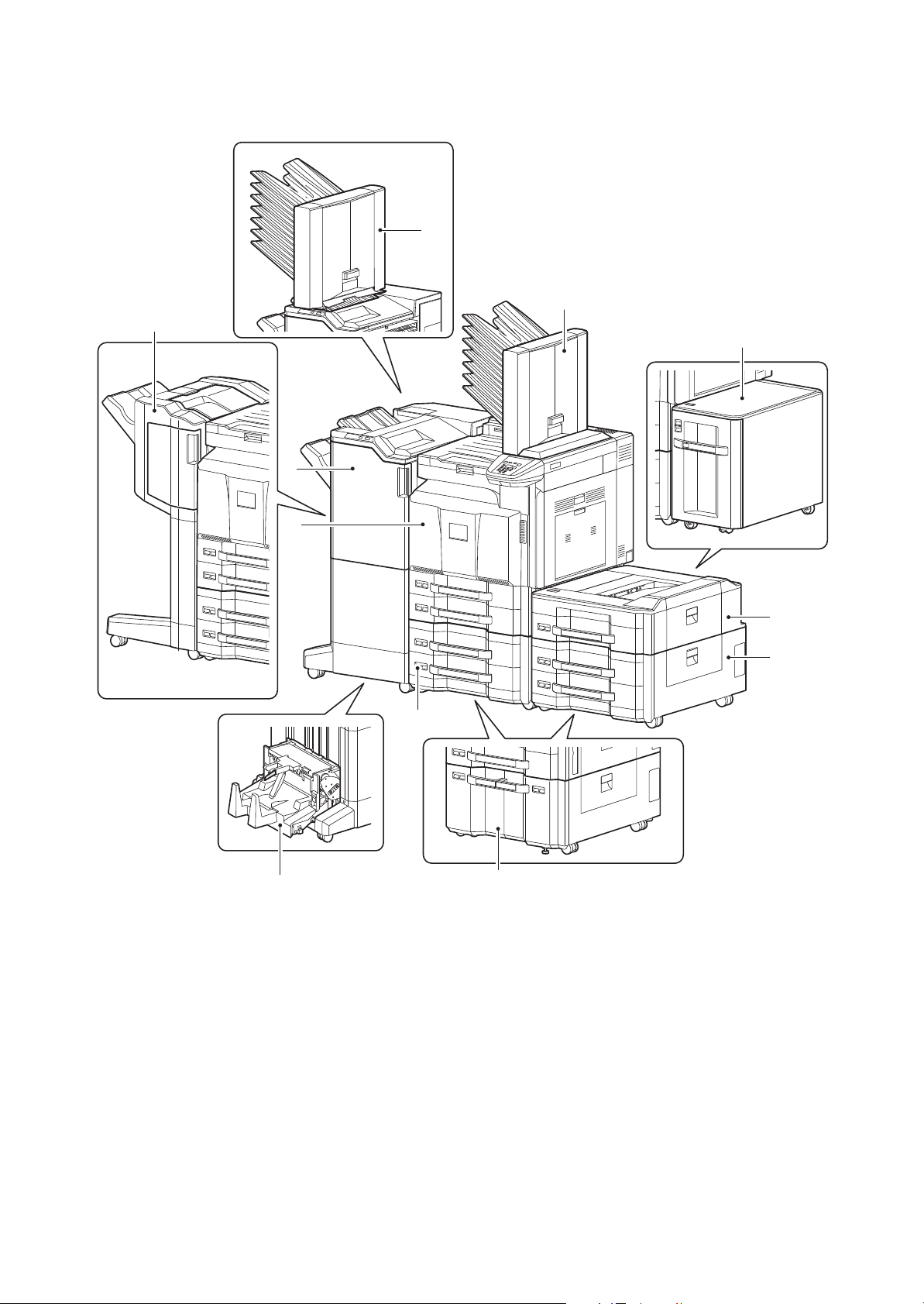
(2) Option
1. Machine
2. Paper feeder
3. Large capacity feeder
4. Side deck
5. Side multi tray
6. Side paper feeder
7. Side large capacity feeder
8. 1000-sheet finisher
9. 4000-sheet finisher
10. Center-folding unit
11. Mailbox
8
2MN/2N1-1
11
11
4
9
10
1
5
6
2
3, 7
Figure 1-1-3
* : The mailbox can be installed either the main unit or the 4000-sheet finisher.(Not installable at the same
time)
1-1-6
Page 21
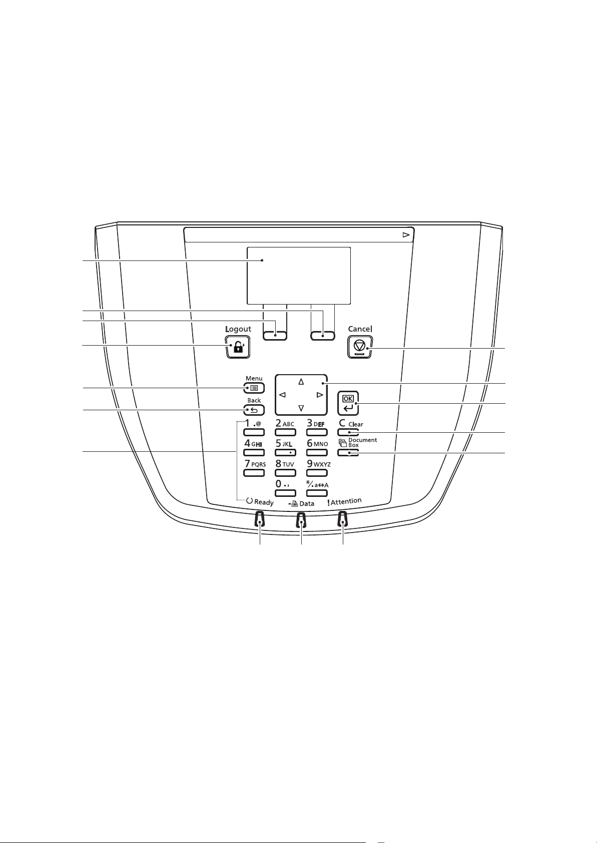
(3) Operation panel
1. Message display
2. Right select key
3. Left select key
4. Logout key
5. Menu key
6. Back key
7. Numeric keys
8. Cancel key
9. Cursor key
10. OK key
11. Clear key
12. Print Box key
13. Ready indicator
14. Data indicator
15. Attention indicator
2MN/2N1
Figure 1-1-4
1-1-7
Page 22
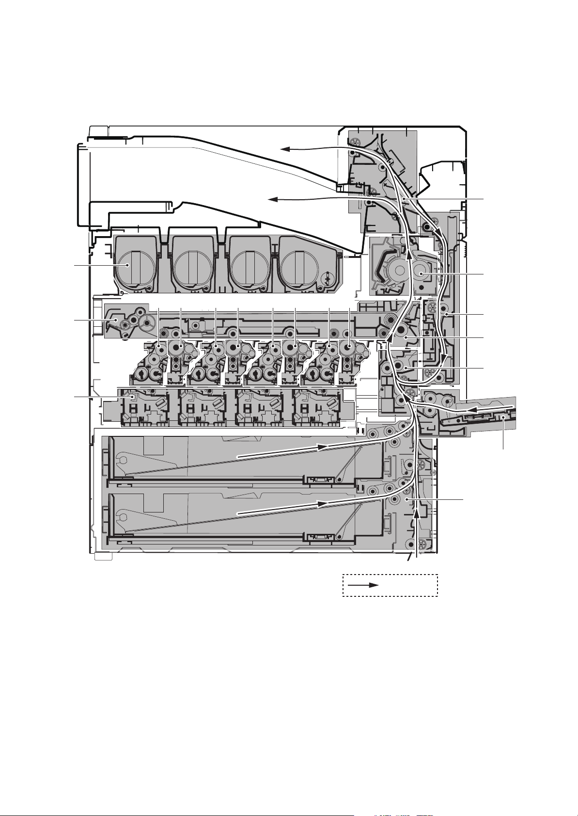
1-1-3 Machine cross section
1. Cassette paper feed section
2. MP tray paper feed section
3. Paper conveying section
4. Laser scanner unit
5. Drum unit K
6. Drum unit M
7. Drum unit C
8. Drum unit Y
9. Developer unit K
10. Developer unit M
11. Developer unit C
12. Developer unit Y
13. Toner container section
14. Primary transfer section
15. Secondary transfer/Separation sections
16. Fuser section
17. Eject/Feed shift sections
18. Duplex section
2MN/2N1
17
13
14
16
12 8 11 7 10 6 9 5
18
15
3
4
2
1
Figure 1-1-5
1-1-8
Paper Path
Page 23
1-2 Installation
1-2-1 Installation environment
1. Temperature: 10 to 32.5°C/50 to 90.5°F
2. Humidity: 15 to 80% RH
3. Power supply: 120 V AC, 12.0 A
220 - 240 V AC, 7.2 A
4. Power source frequency: 50 Hz ± 2%/60 Hz ± 2%
5. Installation location
Avoid direct sunlight or bright lighting. Ensure that the photoconductor will not be exposed to direct sunlight or other strong light when removing paper jams.
Avoid locations subject to high temperature and high humidity or low temperature and low humidity; an
abrupt change in the environmental temperature; and cool or hot, direct air.
Avoid places subject to dust and vibrations.
Choose a surface capable of supporting the weight of the machine.
Place the machine on a level surface (maximum allowance inclination: 1°).
Avoid air-borne substances that may adversely affect the machine or degrade the photoconductor, such
as mercury, acidic of alkaline vapors, inorganic gasses, NOx, SOx gases and chlorine-based organic solvents.
Select a well-ventilated location.
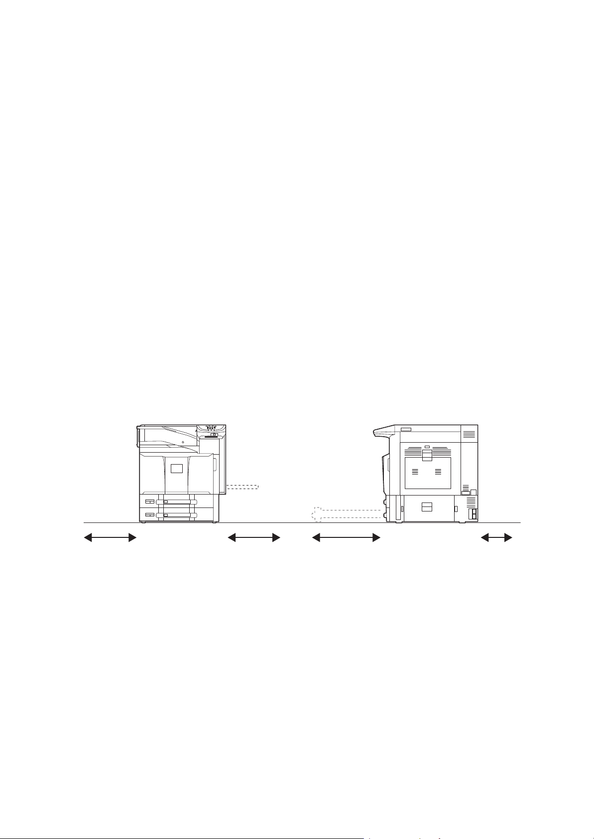
6. Allow sufficient access for proper operation and maintenance of the machine.
Machine front : 100 cm/ 40"
Machine rear : 10 cm/ 4"
Machine right : 35 cm/ 14"
Machine left : 30 cm/ 12"
Machine top : 40 cm/ 15"
2MN/2N1
35 cm (14")30 cm (12") 100 cm (40") 10 cm (4")
Figure 1-2-1
1-2-1
Page 24
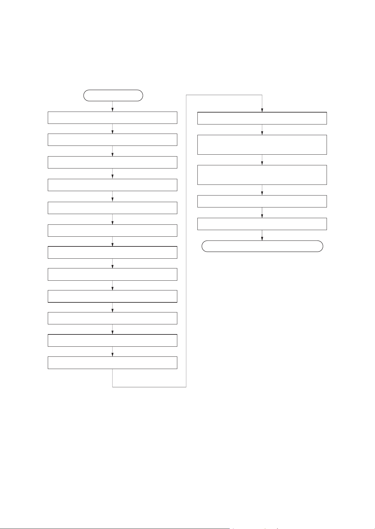
1-2-2 Unpacking and installation
(1) Installation procedure
Start
2MN/2N1-1
Unpacking
Removing the tapes and spacers
Installing the main tray and jobseparator tray
Release of lift plate stopper
Loading paper
Installing the toner containers
Unlocking the developer waste exit
Installing the waste toner box
Installing optional devices
Adjusting the image
Setting the delivery date
(maintenance item U278)
*
Output an own-status report
(maintenance item U000)
Exit maintenance mode
Print out the user setting list
Completion of the machine installation.
Installing the cassette heater (option)
Replacing operation panel sheet
Connect the power cord
*: *:When the finisher has been installed, the job separator tray and the main tray are not needed.
1-2-2
Page 25
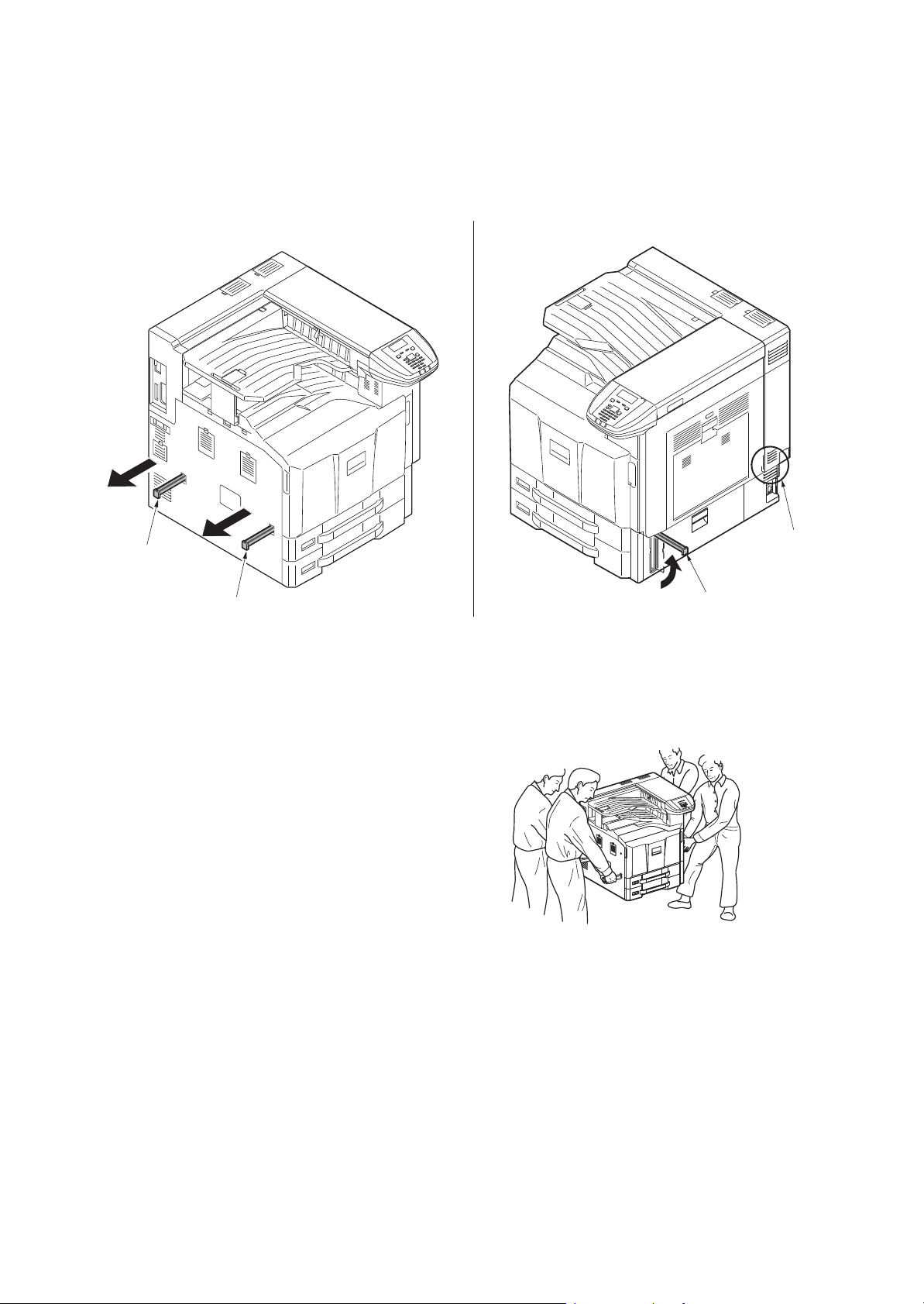
2MN/2N1
Moving the machine
When moving the machine, pull out three carrying handles, and move with carrying handles and the handhold.
Carrying
handle
Carrying
handle
*: Moving this machine is a job for four peo-
ple.
Handhold
Carrying
handle
Figure 1-2-2
1-2-3
Figure 1-2-3
Page 26
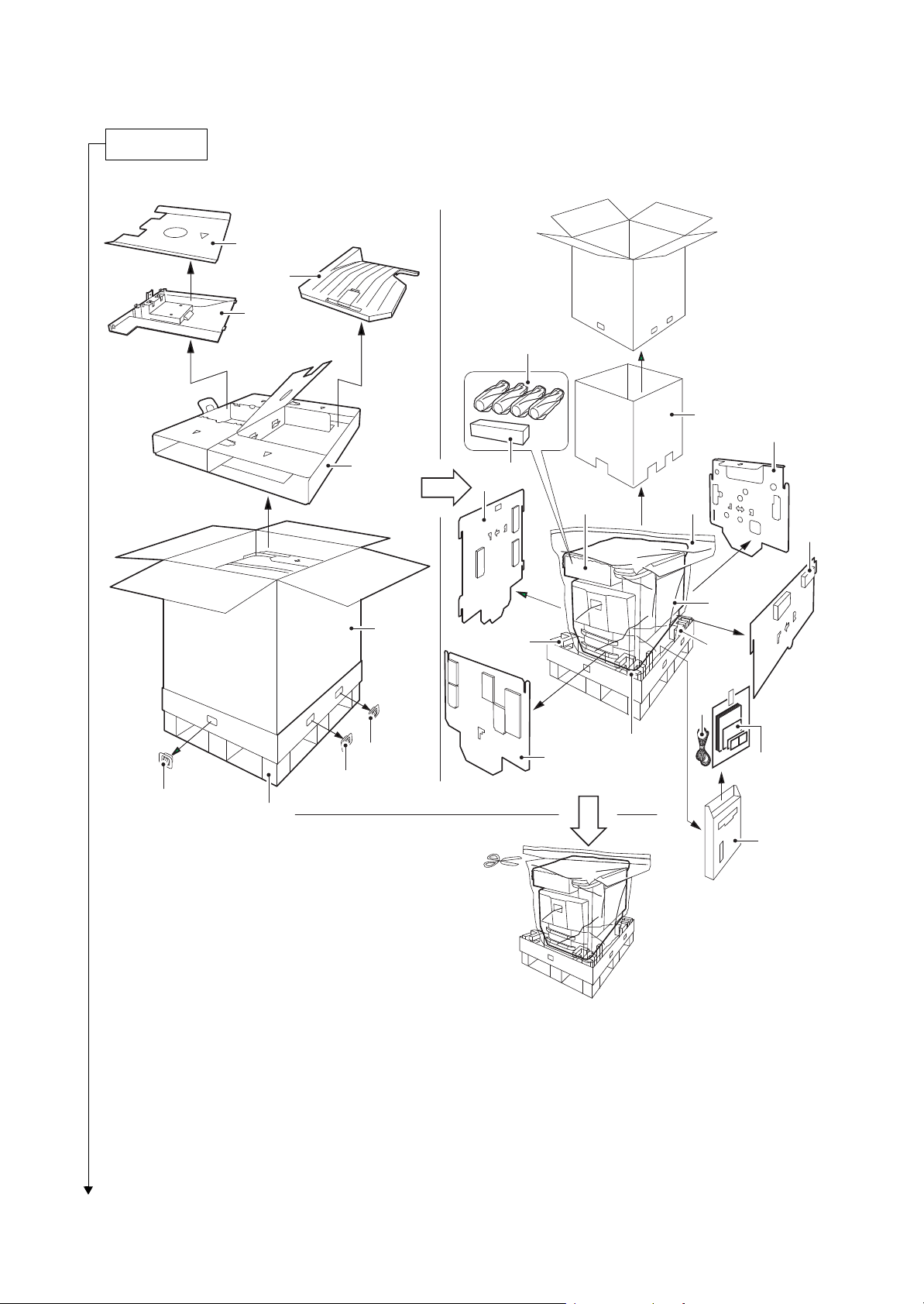
120V model
Unpacking
2MN/2N1
17
18
16
13
3
11
4
14
9
12
13
10
1
2
7
7
20
6
8
6
6
7
21,22,
23,24,25
5
19
Figure 1-2-4
1-2-4
Page 27
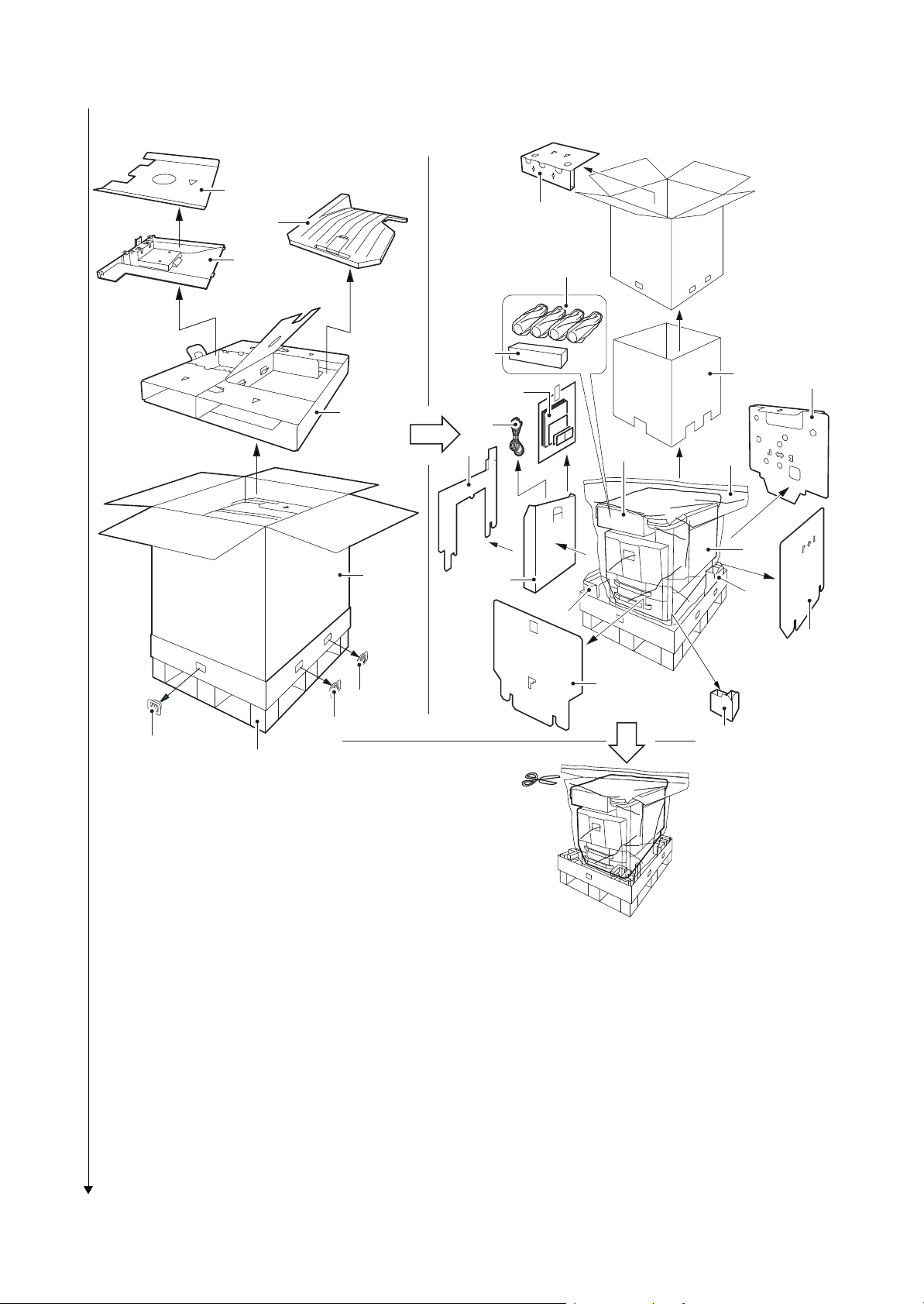
220-240V model
1. Machine
2. Outer case
3. Inner case
4. Spacer A
5. Skid
6. Hinge joints
7. Bottom pad
8. Front pad
9. Left pad
10. Right pad
11. Re a r p a d
12. Top spacer
13. Machine cover
14. Toner container (Y,M,C,K)
15. Waste toner box
16. Main tray
17. Spacer B
18. Job separetor tray
19. Document tray
20. Power cord
21. Plastic bag
22. Paper size plates
23. Paper media plates
24. Pin
25. Operation guide etc.
26. Top pad
2MN/2N1
17
26
18
16
13
14
21,22,
4
23,24,25
3
11
20
9
12
13
1
2
19
7
7
10
8
6
Place the machine on a level surface.
6
6
7
5
Figure 1-2-5
1-2-5
Page 28
2MN/2N1
Removing the tapes
1. Remove two tapes and the protect
sheet.
2. Remove tape and the top spacer.
Protect sheet
Ta pe s
Top spacer
Ta pe
Figure 1-2-6
3. Remove tape and then two protect
sheets.
4. Remove three tapes and then protect
sheet.
5. Remove tape and then silica gel.
Ta pe
Protect sheets
Silica gel
Ta pe
Figure 1-2-7
1-2-6
Page 29

6. Open the front cover and then remove
Ta pe
Ta pe
Ta pe s
Ta pe
Protect sheet
tape.
2MN/2N1
Ta pe
Figure 1-2-8
1. Remove three tapes and then remove
three protect sheet.
2. Remove two tapes.
Figure 1-2-9
1-2-7
Page 30
3. Remove tape.
Installing the main tray and job separator tray
2MN/2N1-1
Ta pe
Figure 1-2-10
*: When the finisher has been installed, the job separator tray and the main tray are not needed.
1. Install the main tray included by latching
in two hooks and securing by one
screw.
Main tray
Hooks
Pin
Figure 1-2-11
1-2-8
Page 31

2MN/2N1-1
Release of lift plate stopper
2. Raise the tray fixing plate.
3. Latch the three hooks to the job separator tray.
4. Load the tray on the tray fixing board
and slide it to secure.
*: Make sure that the two clicks have been
properly locked.
Hook
Jobseparator tray
Hook
Hooks
Hook
Tray fixture plate
Figure 1-2-12
1. Pull cassette 1 and 2 out.
2. Remove the lift plate stopper from each
cassette and attach it to the storage
location.
When moving the machine, attach the
lift plate in original position.
Lift plate
stopper
Cassette
Figure 1-2-13
1-2-9
Page 32

2MN/2N1
Loading paper
1. Squeeze the ends of the bottom of the
paper length guide and move the guide
to fit the length of the paper.
2. Press the guide lock lever to release
the lock.
3. Grasp the paper width adjusting tab and
move the paper width guides to fit the
paper.
Paper length guide
Figure 1-2-14
Guide lock lever
Paper width
adjusting tab
paper width guides
Figure 1-2-15
1-2-10
Page 33

2MN/2N1
4. Align the paper flush against the right
side of the cassette.
*: Before loading the paper, be sure that it is
not curled or folded.
*: Ensure that the loaded paper does not
exceed the level indicated.
*: Make sure that the paper length guide
and the paper width guides are correctly
abut with the paper. Be sure to remove
spaces between the guides and the
paper.
Paper
Figure 1-2-16
1-2-11
Page 34

5. Press the guide lock lever to lock.
2MN/2N1
Guide lock lever
Figure 1-2-17
6. Insert the paper size plate and the
paper media plate.
7. Gently push the cassette back in.
Paper media plate
Paper size plate
Figure 1-2-18
1-2-12
Page 35

1. Open the front cover.
Installing the toner containers
Toner container
Toner container
2. Hold the toner container vertically and
hit the upper part about 3 times. Invert
the toner container so that the other end
is up, and hit in the same way.
3. Hold the toner container horizontally
and shake from side to side about 3
times.
2MN/2N1
4. Install four color toner containers.
5. Turn down the toner container release
levers to lock the four color toner containers.
Figure 1-2-19
K
M
C
Y
Toner container
Toner container
Release lever
Figure 1-2-20
1-2-13
Page 36

2MN/2N1
Unlocking the developer waste exit
Caution
To ease setup, the device was shipped
with the developer unit already replenished
with developer. Therefore, to prevent
developer from spilling during shipping, a
developer shutter is equipped with the
developer unit.
To disengage the shutter, use the following
procedure: Note that if the shutter is not
completely disengaged and retained in
place, the developer in the developer unit
may clog at the outlet causing a damage to
the developer unit.
1. Remove the tape and then remove the
set up leaflet.
*: The setup leaflet must be affixed in posi-
tion before dispatching the machine.
2. Press the fixing pin in four positions and
rotate.
*: Fully insert the fixing pin keeping the line
vertical and rotate by 90 degrees clockwise. Make sure that the central line is
horizontal.
Ta pe
Set up leaflet
[Locked] [Released]
1
2
Fixing pin
Fixing pin
Figure 1-2-21
1-2-14
Page 37

3. Remove a screw and slide the lever
Installing the waste toner box
right wards.
4. Fix the lever using the screw previously
removed at the right screw hole and
unlock the developer waste exit.
*: When the device is shipped again or
removed, use the reverse procedure to
lock in the developer waste exit. Failure
to observe this caution could result in
deteriorated print quality and/or C calls.
2MN/2N1
[Locked] [Released]
3
2
1
Screw
Caution
Before installing the waste toner box,
unlock the developer waste exit (see page
1-2-14).
1. Push the release button and pull out the
waste toner tray.
2. Open the lid and install the waste toner
box.
3. Push the waste toner tray back in.
4. Close the front cover.
Lever
Screw
Figure 1-2-22
Waste toner tray
Release button
Lever
2
1
Lid
Waste toner box
Figure 1-2-23
1-2-15
Page 38

1. Install the optional devices (job separa-
Installing optional devices
Installing the cassette heater (option)
Connect the power cord
Adjusting the image
tor, document finisher and/or fax kit
etc.) as necessary.
1. Install the optional cassette heater as
necessary (see page 1-2-21).
2MN/2N1
1. Connect the power cord to the power
cord connector on rear lower of the
machine.
2. Connect the power plug to the wall outlet.
1. Turn the main power switch on.
2. Check the messages on the operation panel
After completion of warming up, in case to display "Warning for high temperature. Adjust the room temperature." on the operation panel, follow the step 3. (Performing Drum Refresh)
In case to display “Warning for low temperature. Adjust the room temperature.” on the operation panel,
install the machine in the other location this message won’t be shown.
Installing the machine in a low temperature environment could cause image quality problems.
In case to have no display, follow the step 4 (Performing LSU cleaning).
*: Perform the high altitude settings when a leakage is developed on images in a high altitude installation,
such as in Mexico City.
U140 - AC Calb - High Altitude - Mode 2
3. Performing drum refresh (see the operation guide)
Press the Menu key.
In the Adjust/Maint. menu screen, press cursor key to select Service Setting.
Press the OK key.
In the Service Setting. menu screen, press cursor key to select [Durm].
Press [OK]. A confirmation screen appears.
Press [Yes] ([Left select key]).
1-2-16
Page 39

2MN/2N1
Setting the delivery date (maintenance item U278)
4. Performing LSU cleaning (see the operation guide)
In the Adjust/Maint. menu screen, press cursor key to select Service Setting.
Press the OK key.
In the Service Setting. menu screen, press cursor key to select [LSU].
Press the OK key. A confirmation screen appears.
Press [Yes] ([Left select key]).
5. Performing calibration
(see the operation guide,U464 Setting the ID correction operation - performing calibration)
In the Adjust/Maint. menu screen, press cursor key to select ColorCalibration.
Press the OK key. A confirmation screen appears.
Press [Yes] ([Left select key]).
*: Performing color registration (see the operation guide,U469 Adjusting the color registration)
Print Chart (Printing the color registration correction chart)
In the Adjust/Maint. menu screen, press cursor key to select Color Regist.
Press the OK key.
In the Color Regist menu screen, press cursor key to select Detail.
Press the OK key.
In the Detail menu screen, press cursor key to select [Print Chart].
Press the OK key. A confirmation screen appears.
Press [Yes] ([Left select key]).
Adjust Magenta
In the Adjust/Maint. menu screen, press cursor key to select Color Regist.
Press the OK key.
In the Color Regist menu screen, press cursor key to select Detail.
Press the OK key.
In the Detail menu screen, press cursor key to select [Adjust Magenta].
Press the OK key.The Adjust Magenta screen appears.
In the H and V charts for magenta printed in Print Chart above, note the values
where the lines are closest to forming a single straight line.
*:
Values corrected are H-1, H-2, H-3, H-4, H-5, H-6, H-7, V-3.
Highlight the read value using the cursor up or down key and fill the other entries using the left and right
cursor keys.
When you have completed all the values, press the OK key.
The setting is saved and you are returned to the Color Regist. Detail menu screen.
Adjust Cyan and Adjust Yellow
In the Detail menu screen, press cursor key to select [Adjust Cyan] or [Adjust Yellow].
Press the OK key.The Adjust Cyan or Adjust Yellow screen appears.
Using the same procedure as for magenta above, identify the cyan and yellow values
in the color registration correction chart and set them in the printer.
6. Make test prints.
If image quality is unsatisfactory after test printing, execute calibration,
then retry U410-Adjusting the halftone automatically.
1. Press the menu key while pressing and holding the OK and down cursor keys simultaneously.
1-2-17
Page 40

2MN/2N1
Output an own-status report (maintenance item U000)
Exit maintenance mode
Print out the user setting list
Completion of the machine installation
2. Enter the maintenance mode by entering 10871087 using the numeric keys. (see page P.1-3-1)
3. Enter 278 using the numeric keys and press the Ok key.
4. Select [Today].
5. Press the Ok key. The delivery date is set.
6. Press the Back key to exit.
1. Enter 000 using the numeric keys and press the Ok key.
2. Select [Maintenance] and press the Ok key. A status report is output.
3. Press the back key to exit.
1. Enter 001 using the numeric keys and press the Ok key. The machine exits the maintenance mode.
1. Select [Report Print] to output the user various setting reports.
1-2-18
Page 41

(2) Shut-down
To turn main power off, be sure to perform the following before turning the main power switch off.
*: Before proceeding, make sure that the
data lamp is turned off.
*: The hard disk may be operating when the
Data indicator is lit or blinking. Turning off
the main power switch while the hard disk
is operating may cause damage.
Figure 1-2-24
2MN/2N1-1
1. Press menu key.
2. Press the cursor key to select Shut
down.
3. Press OK key. A confirmation screen
appears.
4. Press [Yes] (Left Select key).
5. Follow the instructions on the display to
turn the main power switch off.
Shut down.
Are you sure?
[ Yes ] [ No ]
Completed.
Turn the main power
switch off.
Figure 1-2-25
1-2-19
Page 42

(3) Setting initial print modes
Factory settings are as follows:
2MN/2N1-1
Maintenance
item No.
U253 Switching between double and single counts DBL(A3/Ledger)
U260 Selecting the timing for print counting Eject
U285 Setting service status page On
U323 Setting abnormal temperature and humidity warning On
U325 Setting the paper interval Off/1
U327 Setting the cassette heater control Off
Contents Factory setting
1-2-20
Page 43

1-2-3 Installing the cassette heater (option)
Cassette heater installation requires the following parts:
Parts Quantity Part.No.
Cassette heater set (120V) 1 302K994930
Cassette heater set (240V) 1 302K994940
Supplied parts of cassette heater set (302K994930):
Parts Quantity Part.No.
Cassette heater (120V) 1 302H794620
Wire saddle 3 7YZM610001++H0
Label 1 302KP34220
Connector cover 1 303NF04140
M3 x 8 tap-tight S screw 2 7BB700308H
2MN/2N1
M4 x 8 tap-tight S screw 1 7BB700408H
Supplied parts of cassette heater set (302K994940):
Parts Quantity Part.No.
Cassette heater (240V) 1 302H794610
Wire saddle 3 7YZM610001++H0
Label 1 302KP34220
Connector cover 1 303NF04140
M3 x 8 tap-tight S screw 2 7BB700308H
M4 x 8 tap-tight S screw 1 7BB700408H
1-2-21
Page 44

Procedure
Cassette slider 1
Cassette 1
Cassette slider 2
Release lever
1. After confirming the data lamp is turned
off, perform shut-down on the operation
panel, turn power off, and unplug the
power receptacle(see page P.1-2-19).
2. Pull the cassette 1 forward.
3. Draw out Cassette 1 by releasing the
release lever.
2MN/2N1-1
Figure 1-2-26
4. Pull the cassette 2 forward.
5. Draw out Cassette 2 by releasing the
release lever.
Cassette slider 1
Cassette 2
Release lever
Cassette slider 2
Figure 1-2-27
1-2-22
Page 45

6. Fit three wire saddles on the bottom
Cassette heater
Wire saddles
Wire saddle
Screw
Screw
frame of the machine.
7. Fit the cassette heater using two M3 x 8
screws.
2MN/2N1
Figure 1-2-28
1-2-23
Page 46

8. Connect the connector of the cassette
Cassette heater
Label
Connector cover
Screw
heater to the connector in the rear
frame of the machine.
9. Pass the wire of the cassette heater
through three wire saddles and then
fasten the wire.
2MN/2N1
Wire saddle
Wire saddle
Cassette heater
Connector
10. After installing the cassette heater,
install the connector cover using the M4
× 8 screw.
11. Clean the label with alcohol and then
affix the label.
Figure 1-2-29
Figure 1-2-30
1-2-24
Page 47

12. To install Cassette 1 and Cassette 2,
align the cassette slider 2 and cassette
slider 1 with each other.
13. Push the cassette in fully.
2MN/2N1
Cassette 1, 2
Cassette slider 2
Cassette slider 1
Figure 1-2-31
1-2-25
Page 48

1-2-4 Installing the gigabit ethernet board (option)
Gigabit ethernet board installation requires the following parts:
Parts Quantity Part.No.
Gigabit ethernet board 1 1505JV0UN0 (option)
Procedure
1. After confirming the data lamp is turned
off, perform shut-down on the operation
panel, turn power off, and unplug the
power receptacle (see page P.1-2-19).
2. Open the controller lid.
3. Remove two pins and then remove the
slot cover.
2MN/2N1-1
Slot cover
Figure 1-2-32
Pin
Pin
1-2-26
Page 49

4. Insert the gigabit ethernet board along
the groove in OPT2 and secure the
board with two pins that have been
removed in step 3.
*: Do not directly touch the gigabit ethernet
board terminal.
Hold the top and bottom of the gigabit
ethernet board, or the projection of the
board to insert the gigabit ethernet board.
2MN/2N1
Gigabit
ethernet board
Pin
Pin
5. Plug the modular connector cable into
the line terminal,
6. Close the controller lid.
Groove
Figure 1-2-33
Network cable
1-2-27
Figure 1-2-34
Page 50

1-2-5 Installing the IC card reader holder (option)
IC card reader holder installation requires the following parts:
Parts Quantity Part.No.
IC card reader holder 1 1709AD0UN0 (option)
Relaying USB wire
*1: For internal wirings only
Supplied parts of IC card reader holder (1709AD0UN0):
Card reader case 1 -
Card reader base 1 -
Card reader mount 1 -
Card reader tray 1 -
USB Wire (For extension) 1 -
*
Parts Quantity Part.No.
1 302MN46210
2MN/2N1-1
Pin 3 303NS24410
Clamp 6 7YZM690002++H01
The card reader base, card reader mount, and the pin are packaged as an assembled kit.
For internal wirings
Procedure
1. After confirming the data lamp is turned
off, perform shut-down on the operation
panel, turn power off, and unplug the
power receptacle(see page P.1-2-19).
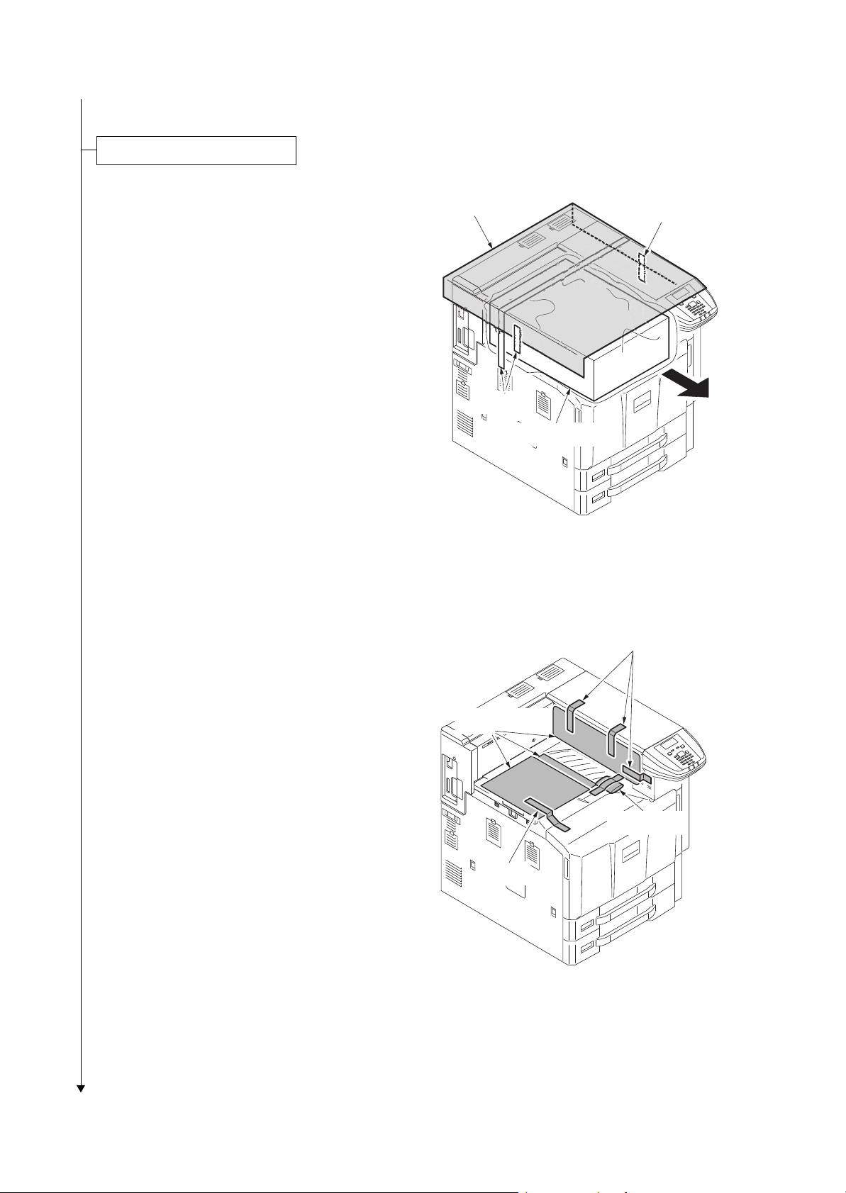
2. Pull the paper conveying unit out.
3. Remove two screws and then remove
the upper right cover.
Upper right
cover
Screw
Screw
1-2-28
Paper conveying
unit
Figure 1-2-35
Page 51

2MN/2N1
4. Remove two screws.
5. Unhook three hooks and then remove
the Left upper cover.
Screws
Hooks
Hook
Left upper cover
6. Remove screw and then remove the
rear tray cover.
Left upper cover
Figure 1-2-36
Rear tray cover
Screw
1-2-29
Figure 1-2-37
Page 52

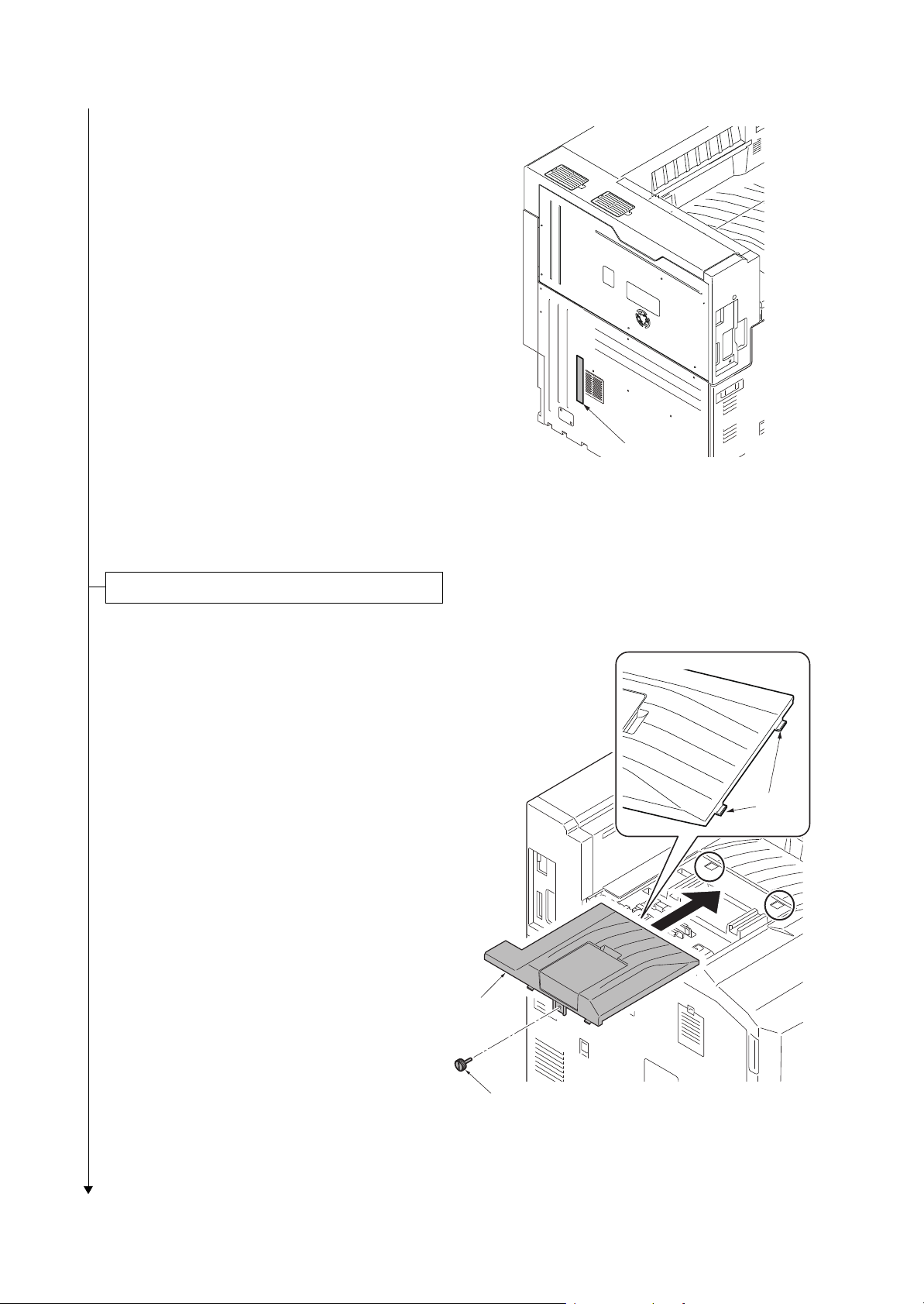
7. Remove seven screws and then
Top cover
Screw
Screw
Screw
Screw
Screw
remove the rear upper cover.
2MN/2N1
Screws
Screws
Screws
Screw
8. Remove five screws and then remove
the Top cover.
Figure 1-2-38
Figure 1-2-39
1-2-30
Page 53

9. Cut out the aperture plate on the upper
right cover using nippers.
2MN/2N1
Upper right cover
Aperture
10. Fit two clamps.
Figure 1-2-40
Clamps
1-2-31
Figure 1-2-41
Page 54

11. Fit four clamps.
2MN/2N1-1
Clamps
Clamp
Figure 1-2-42
12. Release ten wire saddles.
13. Remove two wire holders.
Wire holders
Clamps
Clamps
Clamps
Clamps
Clamps
Figure 1-2-43
1-2-32
Page 55

14. Connect the relaying USB wire to the
USB wire of the IC card reader.
15. Insert the connector of the relaying USB
wire to the main PWB.
16. Fix the USB wire of the IC card reader
using ten wire saddles and two wire
holders.
2MN/2N1-1
17. Pass the USB wire of the IC card reader
through two clamps and then fasten the
wire.
Figure 1-2-44
Clamps
IC card reader
1-2-33
Figure 1-2-45
Page 56

18. .Fix the wirings of extra portion using
two clamps so that the distance of the
USB power line from the clamp to the
IC card reader is approximately
160mm.
2MN/2N1
Clamps
160 mm
IC card reader
Figure 1-2-46
19. Route the IC card reader through the
opening in the upper right cover and fix
the upper right cover using the two
screws.
Upper right
cover
Screw
IC card reader
Screw
Figure 1-2-47
1-2-34
Page 57

20. Remove the pin of the card reader base
r
and then remove the card reader
mount.
2MN/2N1
Card reade
base
Card reader
mount
Pin
21. Fit the card reader mount to the
machine using two pins.
Figure 1-2-48
Right upper
cover
Pins
Card reader
mount
Figure 1-2-49
1-2-35
Page 58

22. Refit the card reader base to card
reader mount using the pin removed in
step 20.
2MN/2N1
Card reader
mount
Card reader
base
Pin
Figure 1-2-50
23. Fit the card reader tray to the card
reader base.
Choose the direction of mounting the IC
card reader according to the depth of
the reader.
10mm to 22mm: Face the mark A
upwards.
Less than 10mm: Face the mark B
upwards.
A
B
A
B
Card reader
tray
Card reader
base
Card reader
tray
1-2-36
Card reader
base
Figure 1-2-51
Page 59

24. Mount the IC card reader on the card
A
A
A
reader base.
2MN/2N1
IC card reader
Figure 1-2-52
25. Hook the two hooks of the card reader
case to fit the card reader case to the
card reader base.
Press its top until it clicks in.
Card reader
case
Hooks
26. Replace the cover which was removed.
Figure 1-2-53
1-2-37
Page 60

For external wirings
r
Procedure
1. After confirming the data lamp is turned
off, perform shut-down on the operation
panel, turn power off, and unplug the
power receptacle(see page P.1-2-19).
2. Remove the pin of the card reader base
and then remove the card reader
mount.
2MN/2N1-1
Card reade
base
Card reader
mount
3. Remove the upper right cover
(see page P.1-2-28).
4. Cut out the aperture plate on the upper
right cover using nippers
(see page P.1-2-31).
5. Replace the cover which was removed.
6. Fit the card reader mount to the
machine using two pins.
Pin
Figure 1-2-54
Right upper
cover
1-2-38
Pins
Card reader
mount
Page 61

7. Refit the card reader base to card
A
A
B
B
Card reader
tray
Card reader
tray
Card reader
Card reader
base
reader mount using the pin removed in
step 2.
2MN/2N1
Figure 1-2-55
Card reader
mount
Card reader
base
Pin
Figure 1-2-56
8. Fit the card reader tray to the card
reader base.
Choose the direction of mounting the IC
card reader according to the depth of
the reader.
10mm to 22mm: Face the mark A
upwards.
Less than 10mm: Face the mark B
upwards.
Figure 1-2-57
1-2-39
Page 62

9. Route the USB wire of the IC card
A
Aperture
USB wire
IC card reader
A
A
reader through the aperture of the card
reader base and mount the IC card
reader on the card reader base.
2MN/2N1
10. Hook the two hooks of the card reader
case to fit the card reader case to the
card reader base.
Press its top until it clicks in.
Figure 1-2-58
Card reader
case
Hooks
Figure 1-2-59
1-2-40
Page 63

2MN/2N1
11. Fit six clamps.
Right side: three
Rear side: three
Clamps
Clamps
12. Pass the USB wire of the IC card reader
through six clamps and then fasten the
wire.
13. Connect the USB wire to the machine.
If the length does not suffice, use the
USB wire supplied.
Figure 1-2-60
Clamps
USB wire
Clamps
1-2-41
Figure 1-2-61
Page 64

2MN/2N1
Enabling IC Card Authentication
Precautions
To install the optional function, you need the License Key. Please access the designated web site of your
dealer or service representative, and register “Machine No.” indicated on your machine and “Product ID” indicated on the License Certificate supplied with the product to issue the License Key.
1. Turn the main power switch on.
2. Press [Menu].
3. Select Op Function. Press OK key.
4. The Login screen appears.
5. With the Login User Name entry field selected, press OK key.The Login User Name entry screen is dis-
played.
6. Enter the Login User Name using the numeric keys then press OK key.
7. Select the Login Password entry field. press OK key.
8. Enter the Login Password with the numeric keys then press OK key.
9. Pressing [Login] ([Right Select]).
10. The Op Functions menu appears.
11. Select the IC Card, then press OK key.
12. Select the License On. then press OK key.
13. Select the Official. then press OK key.
14. To use the application as a trial, select Trial and press OK key.
15. Enter the License key using the numeric keys.
16. When the confirmation screen appears, press [Yes] ([Left Select]).
To use a SSFC card, run maintenance mode U222 and set SSFC.
1-2-42
Page 65

1-2-6 Installing the duct unit (option)
Duct unit installation requires the following parts:
Parts Quantity Part.No.
Duct unit 1 302LC94530
Supplied parts of duct unit (302LC94530):
Parts Quantity Part.No.
Duct A 1 -
Duct B 1 -
Filter 2 -
M3 x 8 tap-tight P screw 2 7BB200308H
2MN/2N1-1
M3 x 8 tap-tight P screw (black)
M3 x 8 tap-tight S screw (black) 2 7BB782308H
*: This option unit cannot be installed together with the finisher.
Procedure
1. After confirming the data lamp is turned
off, perform shut-down on the operation
panel, turn power off, and unplug the
power receptacle(see page P.1-2-19).
2. Fit duct B to duct A using two M3 x 8
tap-tight P screws.
1 7BB282308H
Duct A
Duct B
M3 x 8
tap-tight
P screw
1-2-43
M3 x 8
tap-tight
P screw
Figure 1-2-62
Page 66

2MN/2N1
3. Fit two filters to duct A.
Duct A
Filters
4. Remove the screw A from the rear
lower cover.
Rear lower
cover
1-2-44
Figure 1-2-63
Screw A
Figure 1-2-64
Page 67

5. Fit the duct unit to the machine using
the removed screw A, M3 x 8 tap-tight P
screw (black) and two M3 x 8 tap-tight S
screws (black).
2MN/2N1
M3 x 8 tap-tight
S screws (black)
M3 x 8 tap-tight
P screw (black)
Screw A
Figure 1-2-65
1-2-45
Page 68

2MN/2N1
This page is intentionally left blank.
1-2-46
Page 69

2MN/2N1
1-3 Maintenance Mode
1-3-1 Maintenance mode
The machine is equipped with a maintenance function which can be used to maintain and service the
machine.
(1) Executing a maintenance item
Perform this operation when the panel displays
Ready to print or that the cover is open.
Start
Press the menu key while pressing and
holding the OK and down cursor keys
simultaneously.
Enter “10871087” using
the numeric keys.
( 0 -16digit)
Press the Right Select key for [Enter].
Yes
Yes
Enter the maintenance item
number using the numeric keys.
Press the OK key.
The selected maintenance item is run.
Press the Back key.
Repeat the same
maintenance item?
No
Run another maintenance
item?
No
Enter 001 using the numeric keys
and press the OK key.
End
Maintenance mode is exited.
1-3-1
Page 70

(2) Maintenance modes item list
2MN/2N1
Section
General U000 Outputting an own-status report -
Initialization
Drive,
paper
feed and
paper
conveying system
Item
No.
U001 Exiting the maintenance mode -
U002 Setting the factory default data -
U004 Setting the machine number -
U019 Displaying the ROM version -
U021 Memory initializing -
U024 HDD formatting -
U030 Checking the operation of the motors -
U031 Checking switches and sensors for
U032 Checking the operation of the clutches -
U033 Checking the operation of the solenoids -
U034 Adjusting the print start timing -
Content of maintenance item
45ppm 55ppm
paper conveying
LSU Out Top 0/0/0/0/0/0/0/0/0/0/0/0
LSU Out Left 0/0/0/0/0/0/0/0/0
Initial setting
-
LSU Out Top B/W - 0/0/0/0/0/0
LSU Out Top 3/4 0/0/0/0/0/0
U037 Checking the operation of the fan motors -
U051 Adjusting the deflection in the paper
Paper Loop Amount -5/0/-5/0/
-5/0/-5/0
-6/-1/-5/0
Paper Loop Amount B/W - -8/-8/-8/
Paper Loop Amount 3/4 -2/-2/-2/-2/-3/-2
U052 Setting the fuser motor control
Set Loop Sensor -
Loop Sensor Control On/On/On/On
Set Loop Sensor Valid On
U053 Setting the adjustment of the motor
speed
Motor1
Motor2
12 11
0/0/0/17/0
-7/-1/-7/-1/
-7/-1/-7/-1/
-8/-2/-7/-1
-8/-9/-8
0/0/0/15/0
1-3-2
Page 71

2MN/2N1
Section
Drive,
paper
feed and
paper
conveying system
Item
No.
U053 Motor3 27/0/-30/
Content of maintenance item
45ppm 55ppm
-30/82/0/18/-30/-30/
0/0/0/0
Motor4 -/28 25/22
Motor5 - 0/0/14/0
Motor6 - -16/0/-25/
Motor1 Half 0
Motor2 Half 0/0/0/34/0 0/0/0/30/0
Motor3 Half 54/0/-43/
-43/164/0/
36/-60/-60
Motor1 3/4 0
Motor2 3/4 0/0/0/22/0
Motor3 3/4 35/0/-39/-39/106/0/
23/
-39/-39
Initial setting
-18/0/-27/
-27/73/0/
16/-27/-27/
0/0/0/0
-25/66/0/
15/-24/-24
-36/0/-38/
-38/147/0/
32/-54/-54
-26/0/-39/-39/106/0/
23/
-39/-39
High
voltage
U059 Setting fan mode
Fan Mode Mode1
Cooling Mode 0
U089 Outputting a MIP-PG pattern
U100 Adjusting main high voltage
Adj AC Bias -
Set AC Auto Adj On
Set DC Bias -
Adj DC Bias 0/0/0/0/0/0/0/0 0/0/0/0/0/0/0/0/0
Set Low Temp 1
Set Charger Freq 8807/
Chk Current -
Set AC Gain Auto
U101 Setting the voltage for the primary trans-
fer
-/
10690/
8857
11022/10690/10690
8857
Normal Full 126 131
Normal Half 108 110
Normal 3/4 118 118
1-3-3
Page 72

2MN/2N1
Section
High
voltage
Item
No.
U101 Normal B/W - 135
U106 Setting the voltage for the secondary
Content of maintenance item
Add Color 2/2/5
Add Color 2nd -3/-3/-2/-14
Surround Correct Off
transfer
Light/Normal 1st
Normal2/3 1st
Light/Normal 2nd
Normal2/3 2nd
Light/Normal 1st 3/4(Gloss)
Normal2/3 1st 3/4(Gloss)
Light/Normal 2nd 3/4(Gloss)
Normal2/3 2nd 3/4(Gloss)
Light/Normal 1st B/W
Normal2/3 1st B/W
45ppm 55ppm
143/134/120 150/139/128
207/155/124 220/163/128
Initial setting
131/123/120
180/140/120
- 150/144/128/
Light/Normal 2nd B/W
Normal2/3 2nd B/W
Heavy1 1st 3/4 133/129/124
Heavy1 2nd 3/4 155/150/124
Heavy4/5 1st Half 126/123/119 130/127/122
Heavy4/5 2nd Half 144/140/119 151/146/122
OHP 134/129/124 139/133/128
Bias 1/1/1/-/138/126/133 1/1/1/1/143/130/133
U107 Setting the transfer cleaning voltage -
Belt(A) 202/180/192/- 207/182/192/212
Belt(B) 150/110/130/- 160/110/130/160
U108 Setting separation shift bias -
Output 55/55/55/55/0/0
Output 3/4 55/55/55/55
Output B/W 20/20/20/20
Timing -
Subtraction Value -35
- 183/171/128
U110 Checking the drum count -
U111 Checking the drum drive time -
U117 Checking the drum number -
U118 Displaying the drum history -
U119 Setting the drum -
1-3-4
Page 73

2MN/2N1
Section
High
voltage
Developer U130 Initial setting for the developer -
Item
No.
U122 Checking the transfer belt unit number -
U123 Displaying the transfer belt unit history -
U127 Checking/clearing the transfer count -
U128 Setting transfer high-voltage timing -5/0/13 -5/0/10
U131 Adjusting the toner sensor control volt-
U132 Replenishing toner forcibly
U135 Checking toner motor operation -
U136 Setting toner near end detection 3/3
U139 Displaying the temperature and humidity
Content of maintenance item
45ppm 55ppm
age
Manual 150/150/150/150
Mode Auto
outside the machine
Initial setting
-
-
U140 Displaying developer bias
Sleeve DC 84/84/84/70/-
Sleeve AC 155/155/155/155/-
Mag DC 155/155/155/155/-
Mag AC 160/200/200/200/- 160/200/200/200/160
Sleeve Freq 5345/
Sleeve Duty 68/-
Mag Duty 43/- 43/43
AC Calib 15/15/15/12
U147 Setting for toner applying operation
Mode Mode1
Upper Limit 2.0
Minimum 10
Interval Number 250/100/50
84/84/84/70/70
155/155/155/155/155
155/155/155/155/155
5511/5345/5345/5345
-/
5345/
5345
68/68
Mode1
U148 Setting drum refresh mode 2/2
U155 Checking sensors for toner -
U156 Setting the toner replenishment level
Supply 512/512/512/512/- 512/512/512/512/512
Empty 100/100/100/100/- 100/100/100/100/100
1-3-5
Page 74

2MN/2N1-1
Section
Developer U157 Checking the developer drive time -
Fuser U161 Setting the fuser control temperature
Operation
panel and
support
equipment
Item
No.
U158 Checking the developer count -
U167 Checking/clearing the fuser count -
U169 Checking/setting the fuser power source -
U199 Displaying fuser heater temperature -
U207 Checking the operation panel keys -
U208 Setting the paper size for the side deck Letter (Inch)/A4 (Metric)
U221 Setting the USB host lock function Off
U223 Operation panel lock Unlock
Content of maintenance item
45ppm 55ppm
Warm Up 165/140/80/170/165/
150/50/155
Print 170/5 175/5
Low Power Mode Mode1
Grain Mode Mode0
Initial setting
170/145/80/175/175/
150/50/160
Mode
setting
U234 Setting punch destination Inch (Inch)/Europe Metric (Metric)
U237 Setting finisher stack quantity 0/0
U240 Checking the operation of the finisher -
U241 Checking the operation of the switches
of the finisher
U246 Setting the finisher
Finisher 0/0/0/0/0/0/0/0
Booklet 0/0/0/0/0/0/0/0/0
U247 Setting the paper feed device -
U250 Checking/clearing the maintenance
cycle
U251 Checking/clearing the maintenance
counter
U252 Setting the destination -
U253 Switching between double and single
counts
U260 Selecting the timing for print counting Eject
U265 Setting OEM purchaser code -
600000/600000/300000
DBL(A3/Ledger)
-
0/0/0
U271 Setting the page count 2/3
U278 Setting the delivery date -
U285 Setting service status page On
1-3-6
Page 75

2MN/2N1-1
Section
Mode
setting
Image
processing
Item
No.
U323 Setting abnormal temperature and
U325 Setting the paper interval Off/1
U327 Setting the cassette heater control Off
U332 Setting the size conversion factor
U340 Setting the applied mode 190/1
U345 Setting the value for maintenance due
U410 Setting a Gamma table Table1
U460 Adjusting the conveying sensor
Content of maintenance item
45ppm 55ppm
humidity warning
Rate 1.0
Mode 0
Level 1 1.0
Level 2 2.5
indication
Conveying Sensor 0/0
Initial setting
On
0
On/Off Config Off
U464 Setting the ID correction operation
Permission On
Time Interval 480
Mode Normal
On/Sleep Out On
AP/NE On
Leaving Time 480
Driving Time 300
Timing 3600
Target Value 890/910/910/760/320/320/300/350
Print Rate(B/W) 50
Calib -
Edge Reduction Off
U465 Data reference for ID correction -
U467 Setting the color registration adjustment -
Color Regist On
Timing 10
U468 Checking the color registration data -
U469 Adjusting the color registration -
U474 Checking LSU cleaning operation 1000
U485 Setting the color table -
1-3-7
Page 76

2MN/2N1-1
Section
Image
processing
Others U901 Checking print counts by paper feed
Item
No.
U486 Setting color/black and white operation
U903 Checking/clearing the paper jam counts -
U904 Checking/clearing the call for service
U905 Checking counts by optional devices -
U906 Resetting partial operation control -
U908 Checking the total counter value -
U910 Clearing the print coverage data -
U911 Checking print counts by paper sizes -
U917 Setting backup data reading/writing -
U920 Checking the print counts -
Content of maintenance item
mode
locations
counts
Initial setting
45ppm 55ppm
Mode2
-
-
U927 Clearing the all print counts and
machine life counts (one time only)
U928 Checking machine life counts -
U930 Checking/clearing the charger roller
count
U952 Maintenance mode workflow -
U964 Checking of log -
U969 Checking of toner area code -
U977 Data capture mode -
U984 Checking the developer unit number -
U985 Displaying the developer unit history -
U989 HDD Scan disk -
-
-
1-3-8
Page 77

Contents of the maintenance mode items
Display Output list
Maintenance List of the current settings of the maintenance modes
User Status Outputs the user status page
Service Status Outputs the service status page
Event Outputs the event log
Network Status Outputs the network status page
All Outputs the all reports
Display Description
Ready List of the current settings of the maintenance modes
Active Outputs the user status page
Complete Outputs the service status page
Error Outputs the event log
Item No. Description
U000 Outputting an own-status report
Description
Outputs lists of the current settings of the maintenance items, and paper jam and service call
occurrences. Outputs the event log or service status page. Also sends output data to the USB
memory.
Purpose
To check the current setting of the maintenance items, or paper jam or service call occurrences.
Before initializing or replacing the backup RAM, output a list of the current settings of the maintenance items to reenter the settings after initialization or replacement.
Method
1. Press the OK key.
2. Select the item to be output using the cursor up/down keys.
2MN/2N1
3. Press the OK key. A list is output.
4. Press the OK key. The interrupt print mode is entered and a list is output.
When A4/Letter paper is available, a report of this size is output. If not, specify the paper feed
location.
The output status is displayed.
1-3-9
Page 78

Item No. Description
Display Output list
Print Outputs the report
USB (Text) Sends output data to the USB memory (text type)
USB (HTML) Sends output data to the USB memory (HTML type)
U000 Method: Send to the USB memory
1. Perform shut-down on the operation panel, turn power off (see page p.1-2-19).
2. Insert USB memory in USB memory slot.
3. Turn the main power switch on.
4. Enter the maintenance item.
5. Press the OK key.
6. Select the item to be send.
7. Select [Text] or [HTML].
8. Press the OK key.
Output will be sent to the USB memory.
Completion
Press the Back key. The screen for selecting a maintenance item No. is displayed.
2MN/2N1-1
1-3-10
Page 79

Item No. Description
No. Items Description
(1) System version
(2) System date
(3) Engine soft version
(4) Engine boot version
U000 Event log
Event Log
Printer
(1)
Firmware version 2MN_2000.000.000 2010.10.27
(2)
27/Oct/2010 08:40
[XXXXXXXX][XXXXXXXX][XXXXXXXX][XXXXXXXX]
2MN/2N1
(6)(5)(4)(3)
Paper Jam Log Counter Log
#
Count.
16
9999999
15
8888888
14
7777777
13
6666666
12
5555555
11
4444444
10
3333333
9
2222222
8
1111111
7
999999
6
888888
5
777777
0501.01.08.01.01
4
666666
3
555555
2
444444
1
(9)
Service Call Log
#
Count.
8
1111111
7
999999
6
888888
5
777777
4
666666
3
555555
2
444444
1
(10)
Maintenance Log
# Count.
Log Data Nothing...
Unknown toner Log
(11)
#
Count.
5
1111111
4
999999
3
888888
2
777777
1
666666
Event Descriprions
0501.01.08.01.01
4002.01.08.01.01
0501.01.08.01.01
4002.01.08.01.01
0501.01.08.01.01
4002.01.08.01.01
0501.01.08.01.01
4002.01.08.01.01
0501.01.08.01.01
4002.01.08.01.01
0501.01.08.01.01
4002.01.08.01.01
0501.01.08.01.01
(a) (b) (c) (d) (e)
4002.01.08.01.01
0501.01.08.01.01
1
4002.01.08.01.01
Service Code
01.6000
01.2100
01.4000
01.6000
01.2100
01.4000
01.6000
1
01.2100
Item.
Item.
01.00
01.00
01.00
01.00
01.00
(12)(8)
J0000:
(f) (g) (h)
J0001:
J0002:
J0003:
J0004:
J0005:
J0006:
J0007:
J0008:
J0009:
J0010:
J0012:
J0013:
J0014:
J0015:
J0016:
J0017:
J0018:
J0019:
J0020:
J0021:
J0022:
J0023:
J0024:
J0025:
J0026:
J0027:
J0028:
J0029:
J0030:
J0031:
J0032:
J0033:
J0034:
J0035:
J0036:
J0037:
J0038:
J0039:
J0040:
222
999
J0041:
0
J0042:
1
J0043:
11
J0044:
J0045:
1
J0046:
1
J0047:
1
J0048:
1
J0049:
1
J0050:
1
1
1
1
1
1
1
1
1
1
1
1
1
1
1
1
1
1
1
1
1
1
1
1
1
1
1
1
1
1
1
C0000:
1
C0001:
1
C0002:
1
C0003:
1
C0004:
1
C0005:
1
C0006:
1
C0007:
1
C0008:
1
C0009:
C0010:
C0011:
C0012:
C0013:
C0014:
C0015:
C0016:
C0017:
C0018:
C0019:
C0020:
C0021:
C0022:
C0023:
10
12
13
14
15
16
17
18
19
20
21
22
23
0
T00:
T01:
T02:
T03:
T04:
T05:
10
20
30
40
50
999
1
2
3
4
5
6
7
8
9
11
Detail of event log
Figure 1-3-1
1-3-11
(7)
[XXXXXXXXXXXXXXXX]
Page 80

Item No. Description
No. Items Description
(5) Controller BROM version
(6) Operation panel mask version
(7) Machine serial number
(8) Paper Jam
Log
# Count. Event
Remembers 1 to 16 of
occurrence. If the occurrence of the previous
paper jam is less than
16, all of the paper jams
are logged. When the
occurrence excesseds
16, the oldest occurrence is removed.
The total page count
at the time of the
paper jam.
Log code (hexadecimal, 5 categories)
(a) Cause of a paper
jam
(b) Paper source
(c) Paper size
(d) Paper type
(e) Paper eject
(a) Cause of paper jam (Hexadecimal)
For details on the case of paper jam, refer to Paper Misfeed Detection.
(P.1-4-2)
(b) Detail of paper source (Hexadecimal)
00: MP tray
01: Cassette 1
02: Cassette 2
03: Cassette 3 (paper feeder/large capacity feeder)
04: Cassette 4 (paper feeder/large capacity feeder)
05: Cassette 5 (side multi tray/side deck)
06: Cassette 6 (side paper feeder/side large capacity feeder)
07: Cassette 7 (side paper feeder/side large capacity feeder)
08 to 09: Reserved
(c) Detail of paper size (Hexadecimal)
00: (Not specified)
01: Monarch
02: Business
03: International DL
04: International C5
05: Executive
06: Letter-R
86: Letter-E
07: Legal
08: A4R
88: A4E
09: B5R
89: B5E
0A: A3
0B: B4
0C: Ledger
0D: A5R
0E: A6
0F: B6
10: Commercial #9
11: Commercial #6
12: ISO B5
13: Custom size
1E: C4
1F: Postcard
20: Reply-paid post-
card
21: Oficio II
22: Special 1
23: Special 2
24: A3 wide
25: Ledger wide
26: Full bleed paper
(12 x 8)
27: 8K
28: 16K-R
A8: 16K-E
32: Statement-R
B2: Statement-E
33: Folio
34: Western type 2
35: Western type 4
U000 Detail of event log
2MN/2N1
1-3-12
Page 81

Item No. Description
No. Items Description
(8)
cont.
Paper Jam
Log
(d) Detail of paper type (Hexadecimal)
01: Plain
02: Transparency
03: Preprinted
04: Labels
05: Bond
06: Recycled
07: Vellum
08: Rough
09: Letterhead
0A: Color
0B: Prepunched
0C: Envelope
0D: Cardstock
0E: Coated
0F: 2nd side
10: Media 16
11: High quality
15: Custom 1
16: Custom 2
17: Custom 3
18: Custom 4
19: Custom 5
1A: Custom 6
1B: Custom 7
1C: Custom 8
(e) Detail of paper eject location (Hexadecimal)
01: Face down (FD)
02: Face up (FU)/1000-sheet finisher face up (FU)/
4000-sheet finisher left sub tray (FU)
03: 1000-sheet finisher face down (FD)
4000-sheet finisher main tray (FD)
05: Job separator tray
06: 4000-sheet finisher right sub tray (FU)
07: 4000-sheet finisher left sub tray (FD)
09: 4000-sheet finisher right sub tray (FD)
0A: Center-folding unit tray
0B: Mailbox tray 1 (FD)
0C: Mailbox tray 1 (FU)
15: Mailbox tray 2 (FD)
16: Mailbox tray 2 (FU)
1F: Mailbox tray 3 (FD)
20: Mailbox tray 3 (FU)
29: Mailbox tray 4 (FD)
2A: Mailbox tray 4 (FU)
33: Mailbox tray 5 (FD)
34: Mailbox tray 5 (FU)
3D: Mailbox tray 6 (FD)
3E: Mailbox tray 6 (FU)
47: Mailbox tray 7 (FD)
48: Mailbox tray 7 (FU)
04/0D/0E: Reserved
U000
2MN/2N1
1-3-13
Page 82

Item No. Description
No. Items Description
(9) Service Call
Log
# Count. Service Code
Remembers 1 to 8
of occurrence of self
diagnostics error. If
the occurrence of
the previous diagnostics error is less
than 8, all of the
diagnostics errors
are logged.
The total page
count at the time of
the self diagnostics
error.
Self diagnostic error code
(See page 1-4-27)
Example:
01.6000
01: Self diagnostic error
6000: Self diagnostic error
code number
(10) Maintenance
Log
# Count. Item
Remembers 1 to 8
of occurrence of
replacement. If the
occurrence of the
previous replacement of toner container is less than 8,
all of the occurrences of replacement are logged.
The total page
count at the time of
the replacement of
the toner container.
Code of maintenance
replacing item
(1 byte, 2 categories)
First byte (Replacing item)
01: Toner container
Second byte
(Type of replacing item)
00: Black
01: Cyan
02: Magenta
03: Yellow
First byte (Replacing item)
02: Maintenance kit
Second byte
(Type of replacing item)
01: MK-8505A
02: MK-8505B
03: MK-8505C
(11) Unknown
Toner Log
# Count. Item
Remembers 1 to 5
of occurrence of
unknown toner
detection. If the
occurrence of the
previous unknown
toner detection is
less than 5, all of the
unknown toner
detection are
logged.
The total page
count at the time of
the toner empty
error with using an
unknown toner
container.
Unknown toner log code
(1 byte, 2 categories)
First byte
01: Toner container (Fixed)
Second byte
00: Black
01: Cyan
02: Magenta
03: Yellow
U000
2MN/2N1
1-3-14
Page 83

Item No. Description
No. Items Description
(12) Counter Log
Comprised of
three log counters including
paper jams, self
diagnostics
errors, and
replacement of
the toner container.
(f) Paper jam (g) Self diagnostic
error
(h) Maintenance item
replacing
Indicates the log
counter of paper
jams depending on
location.
Refer to Paper Jam
Log.
All instances including those are not
occurred are displayed.
Indicates the log
counter of self diagnostics errors
depending on
cause.
Example:
C6000: 4
Self diagnostics
error 6000 has happened four times.
Indicates the log counter depending on the
maintenance item for
maintenance.
T: Toner container
00: Black
01: Cyan
02: Magenta
03: Yellow
M: Maintenance kit
00: MK-8505A
01: MK-8505B
02: MK-8505C
Example:
T00: 1
The toner container has
been replaced once.
U000
2MN/2N1
1-3-15
Page 84

Item No. Description
U000 Service status page (1)
2MN/2N1-1
Service Status Page
Printer
(1)
Firmware version 2MN_2000.001.001 2011.10.27
Controller Information
Memory status
Standard Size 1.0 GB
(7)
Option Slot 1.0 GB
(8)
(9)
Total Size
Time
(10)
Local Time Zone
Date and Time
(11)
(12)
Time Server
Installed Options
Paper feeder
(13)
Side Feeder
(14)
Finisher
(15)
(16)
IC Card Authentication Kit (B)
(17)
Security Kit (E)
Data Security Kit (E)
(18)
UG-33
UG-34
(19)
USB Keyboard
(20)
USB Keyboard Type
(21)
Print Coverage
(22)
Average(%)
(23)
K: 1.10
C: 2.20
M: 3.30
Y: 4.40
Last Page K/C/M/Y(%)
(24)
(25)
FRPO Status
Default Pattern Switch
Default Font Number
/ Usage Page(A4/Letter Conversion)
/ 1111111 . 11
/ 2222222.22
/ 3333333.33
/ 4444444.44
1.00 / 2.22 / 3.33 / 4.44
2.0 GB
+01:00 Amsterdam
27/10/2010 12:00
10.183.53.13
Cassette (500 x 2)
Cassette (3000)
1000-Finisher
Installed
Installed
Installed
Installed
Connected
US-English
B8
C5*1000+C2*100+C3
.
.
.
.
.
.
.
.
0
00000
e-MPS error control
RP Code
1234 5678 9012
(26)
5678 9012 3456
(27)
9012 3456 7890
(28)
3456 7890 1234
(29)
(2)
27/10/2011 12:00
(3) (4) (5)
[XXXXXXXX] [XXXXXXXX] [XXXXXXXX]
.
.
.
.
.
.
.
.
.
.
.
.
.
.
.
.
.
.
.
.
.
.
.
.
.
.
.
.
.
Y6
0
1
Figure 1-3-2
1-3-16
(6)
[XXXXXXXXXX]
Page 85

Item No. Description
U000 Service status page (2)
Service Status Page
Printer
2MN/2N1-1
27/10/2011 12:00
Firmware version 2MN_2000.001.001 2011.10.27
Engine Information
(30)
NVRAM Version
(31)
MAC Address
(34) (35)
1/2
(36)
100/100
(37)
0/0/0/0/0/0/0/0
(38)
0000000/0000000/0000000/0000000/0000000/0000000/0000000/0000000/0000000/0000000/
0000000/0000000/0000000/0000000/0000000/0000000/0000000/0000000/0000000/0000000/0000000/0000000/
F00/U00/0/0/0/0/30/30/70/70/abcde/1/0/1/
(53)
0000/0000/0000/0000/0000/0000/0000/0000/0000/0000/0000/0000/0000/0000/0000/
0000/0000/0000/0000/0000/0000/0000/0000/0000/0000/
(54)
0000/0100/0500/1000/0000/0100/0500/1000/0000/0100/0500/1000/0000/0100/0500/1000/
0000/0100/0500/1000/0000/0100/0500/1000/0000/0100/0500/1000/0000/0100/0500/1000/
00000000000000000000000000000000/0000000000000000000000000000000000000000/000000/
(58)
0000000000000000/0000000000000000/0000000000000000/0000000000000000/0000000000000000/0000000000000000/000000000000/
0000000000000000/0000000000000000/0000000000000000/0000000000000000/0000000000000000/0000000000000000/000000000000/
0000000000000000/0000000000000000/0000000000000000/0000000000000000/0000000000000000/0000000000000000/000000000000/
0000000000000000/0000000000000000/0000000000000000/0000000000000000/0000000000000000/0000000000000000/000000000000/
(59)
0000000000000000/0000000000000000/0000000000000000/0000000000000000/0000000000000000/0000000000000000/000000000000/
0000000000000000/0000000000000000/0000000000000000/0000000000000000/0000000000000000/0000000000000000/000000000000/
0000000000000000/0000000000000000/0000000000000000/0000000000000000/0000000000000000/0000000000000000/000000000000/
0000000000000000/0000000000000000/0000000000000000/0000000000000000/0000000000000000/0000000000000000/000000000000/
(60)
0000000000000000/0000000000000000/0000000000000000/0000000000000000/0000000000000000/0000000000000000/000000000000/
0000000000000000/0000000000000000/0000000000000000/0000000000000000/0000000000000000/0000000000000000/000000000000/
(61)
0000000000000000/0000000000000000/0000000000000000/0000000000000000/0000000000000000/0000000000000000/000000000000/
0000000000000000/0000000000000000/0000000000000000/0000000000000000/0000000000000000/0000000000000000/000000000000/
0000000000000000/0000000000000000/0000000000000000/0000000000000000/0000000000000000/0000000000000000/000000000000/
0000000000000000/0000000000000000/0000000000000000/0000000000000000/0000000000000000/0000000000000000/000000000000/
(62)
0000000000000000/0000000000000000/0000000000000000/0000000000000000/0000000000000000/0000000000000000/000000000000/
0000000000000000/0000000000000000/0000000000000000/0000000000000000/0000000000000000/0000000000000000/000000000000/
0000000000000000/0000000000000000/0000000000000000/0000000000000000/0000000000000000/0000000000000000/000000000000/
0000000000000000/0000000000000000/0000000000000000/0000000000000000/0000000000000000/0000000000000000/000000000000/
(63)
0000000000000000/0000000000000000/0000000000000000/0000000000000000/0000000000000000/0000000000000000/000000000000/
(64)
12345678/11223344/00001234abcd567800001234abcd5678/01234567890123456789012345678901/0008/00/07
12345678/11223344/00001234abcd567800001234abcd5678/01234567890123456789012345678901/0008/00/07
12345678/11223344/00001234abcd567800001234abcd5678/01234567890123456789012345678901/0008/00/07
12345678/11223344/00001234abcd567800001234abcd5678/01234567890123456789012345678901/0008/00/07
(65)
XXXXXXXX
[2MN_81BR.001.010]
(69)
00070107FE/0700FE00FE/00FE000100/0000000000/0000000000/0000000000/00000A010A/0A0A0A3200/0000000000/0000000000/
0008000000/080000001D/0096009B00/9B009BFFFB/0082000000/000000001F/0000002C00/0000000000/0000000000/0000000000/
0000000000/0000000000/0000000000/0000000000/00
(70) (71)
0/3/
0/12.3/56.7/
0/0 2010/12/15 12:34:56
1/5/
(76)(77)
1/1/
(78)(79)
ABCDEFGHIJKL/ABCDEFGHIJKL/ABCDEFGHIJKL/ABCDEFGHIJKL/
[ABCDEFGHIJ][ABCDEFGHIJ]
(72) (73) (74)
(75)
_1F31225_1F31225
00:C0:EE:D0:01:0D
(39) (40) (41) (42) (43) (44) (45) (46) (47) (48) (49) (50) (51) (52)
(68)
(66) (67)
(80)
[XXXXXXXX] [XXXXXXXX] [XXXXXXXX]
Send Information
(32)
Date and Time
(33)
Address
(55) (56) (57)
11/10/27
2
Figure 1-3-3
1-3-17
[XXXXXXXXXX]
Page 86

Item No. Description
No. Description Supplement
(1) Firmware version -
(2) System date -
(3) Engine soft version -
(4) Engine boot version -
(5) Operation panel mask version -
(6) Machine serial number -
(7) Standard memory size -
(8) Option memory size
(9) Total memory size
(10) Local time zone -
(11) Report output date Day/Month/Year hour:minute
(12) NTP server name -
(13) Presence or absence of the
paper feeder
Paper feeder/Large capacity feeder/Not Installed
(14) Presence or absence of the side
feeder
Side deck/Side multi tray/Side paper feeder/
Side large capacity feeder/Not Installed
(15) Presence or absence of the
finisher
1000-sheet finisher/4000-sheet finisher/
Not Installed
(16) Presence or absence of the IC
card authentication kit
Installed/Not Installed/Trial
(17) Presence or absence of the
data security kit
Installed/Not Installed
(18) Presence or absence of the
UG-33
Installed/Not Installed
(19) Presence or absence of the
UG-34
Installed/Not Installed
(20) Presence or absence of the
USB keyboard
Connected/Not connected
(21) USB keyboard setting display US-English/US-English with Euro/German/French
(22) Page of relation to the A4/Letter -
(23) Average coverage for total Black/Cyan/Magenta/Yellow
(24) Coverage on the final output
page
-
(25) FRPO setting -
(26) RP code Code the engine software version and the date of
update.
(27) RP code Code the main software version and the date of
update.
U000 Detail of service status page
2MN/2N1
1-3-18
Page 87

Item No. Description
No. Description Supplement
(28) RP code Code the engine software version and the date of
the previous update.
(29) RP code Code the main software version and the date of the
previous update.
(30) NV RAM version _ 1F3 1225 _ 1F3 1225
(a) (b) (c) (d) (e) (f)
(a) Consistency of the present software version
and the database
_ (underscore): OK
* (Asterisk): NG
(b) Database version
(c) The oldest time stamp of database version
(d) Consistency of the present software version
and the ME firmware version
_ (underscore): OK
* (Asterisk): NG
(e) ME firmware version
(f) The oldest time stamp of the ME database ver-
sion
Normal if (a) and (d) are underscored, and (b) and
(e) are identical with (c) and (f).
(31) Mac address -
(32) The last sent date and time -
(33) Transmission address -
(34) Destination information -
(35) Area information -
(36) Margin settings Top margin/Left margin
(37) Margin/Page length/Page width
settings
Top margin integer part/Top margin decimal part/
Left margin integer part/Left margin decimal part/
Page length integer part/Page length decimal part/
Page width integer part/Page width decimal part
(38) Life counter (The first line) Machine life/MP tray/Cassette 1/Cassette 2/
Cassette 3/Cassette 4/Cassette 5/Cassette 6/
Cassette 7/Duplex
Life counter (The second line) Drum unit K/Drum unit C/Drum unit M/Drum unit Y/
Transfer belt unit/Developer unit K/
Developer unit C/Developer unit M/
Developer unit Y/Maintenance kit A/
Maintenance kit B/Maintenance kit C
U000
2MN/2N1
1-3-19
Page 88

Item No. Description
No. Description Supplement
(39)
Panel lock information F00: Off/F01: Partial lock 1/F02:Partial lock 2
F03: Partial lock 3/F04: Full lock
(40)
USB information U00: Not installed/U01: Full speed/U02: Hi speed
(41) Paper handling information 0: Paper source unit select/1: Paper source unit
(42) Color printing double count
mode
0: All single counts
1: A3, Single count, Less than 420 mm (length)
2: Legal, Single count, 356 mm or less (length)
3: Folio, Single count, Less than 330 mm (length)
(43) Black and white printing double
count mode
0: All single counts
1: A3, Single count, Less than 420 mm (length)
2: Legal, Single count, 356 mm or less (length)
3: Folio, Single count, Less than 330 mm (length)
(44) Billing counting timing -
(45) Temperature (machine inside) -
(46) Temperature (machine outside) -
(47) Relative humidity
(machine outside)
-
(48) Humidity (machine inside) -
(49) Fixed assets number -
(50) Job end judgment time-out time -
(51) Job end detection mode -
(52) Prescribe environment reset 0: Off
1: On
(53) Media type attributes
1 to 28 (Not used: 18, 19, 20)
Weight settings Fuser settings
0: Light 0: High
1: Normal 1 1: Middle
2: Normal 2 2: Low
3: Normal 3 3: Vellum
4: Heavy 1 Duplex settings
5: Heavy 2 0: Disable
6: Heavy 3 1: Enable
6: Heavy 4
6: Heavy 5
7: Extra Heavy
(54) Calibration information Black/Cyan/Magenta/Yellow
(55) Calibration information -
(56) Calibration information -
(57) Calibration information -
(58) Calibration information -
(59) Calibration information -
U000
2MN/2N1
1-3-20
Page 89

Item No. Description
No. Description Supplement
(60) Calibration information Black/Cyan/Magenta/Yellow
(61) Calibration information -
(62) Calibration information -
(63) Calibration information -
(64) RFID information -
(65) RFID reader/writer version infor-
mation
-
(66) Option messege version -
(67) Color table version for printer -
(68) Color table 2 version for printer -
(69) Maintenance information -
(70) Altitude 0: Standard
1: High altitude 1
2: High altitude 2
(71) Charger roller correction 1 to 5
(72) Configuring toner coverage
counters
0: Full-color count display
1: Color coverage count display
(73) Low coverage setting 0.1 to 100.0
(74) Middle coverage setting 0.1 to 100.0
(75) Data Sanitization information -
(76) Toner low setting 0: Enabled
1: Disabled
(77) Toner low detection level 0 to 100 (%)
(78) Limiting shifting for one-page
document
0: Disabled
1: Enabled
(79) Setting confirmation display for
banner printing
(80) Drum serial number Black/Cyan/Magenta/Yellow
Code conversion
ABCDEFGH I J
0123456789
U000
2MN/2N1-1
1-3-21
Page 90

Item No. Description
Codes Description
0001 Entity error
0002 Counter error
0003 OS error
0020 Engine error
U001 Exiting the maintenance mode
Description
Exits the maintenance mode and returns to the normal print mode.
Purpose
To exit the maintenance mode.
Method
1. Press the OK key. The normal print mode is entered.
U002 Setting the factory default data
Description
Restores the machine conditions to the factory default settings.
Purpose
Method
1. Press the OK key.
2. Select [Mode1(All)].
3. Press the OK key.
4. Exit the maintenance mode, perform shut-down, and turn the main power switch to off and on
again. Allow more than 5 seconds between Off and On.
* : An error code is displayed in case of an initialization error.
When errors occurred, turn main power switch off then on, and execute initialization using
maintenance item U002.
2MN/2N1-1
Error codes
1-3-22
Page 91

Item No. Description
Display Description
Machine No. Displays the machine serial number
Display Description
Machine No.(Main) Displays the machine serial number of main
Machine No.(Eng) Displays the machine serial number of engine
U004 Setting the machine number
Description
Sets or displays the machine number.
Purpose
To check or set the machine number.
Method
1. Press the OK key.
If the machine serial number of engine PWB matches with that of main PWB
If the machine serial number of engine PWB does not match with that of main PWB
2MN/2N1-1
Setting
Carry out if the machine serial number does not match.
1. Select [Execute].
2. Press the OK key. Writing of serial No. starts.
3. Exit the maintenance mode, perform shut-down, and turn the main power switch to off and on
again. Allow more than 5 seconds between Off and On.
Completion
Press the Back key. The screen for selecting a maintenance item No. is displayed.
1-3-23
Page 92

Item No. Description
Display Description
New ID Enter a new 8-digit ID
New ID(Reconfirm) Enter a new 8-digit ID (to confirm)
Initialize Initialize the ID
U010 Setting the maintenance mode ID
Description
Sets the maintenance mode ID.
Purpose
Modify maintenance mode ID for more security.
Method
1. Press the OK key.
Setting
1. Select [New ID].
2. Enter a new 8-digit ID on ten keys (0 – 9, *, #). * and # are mandatory to contain.
3. Select [New ID(Reconfirm)].
4. Enter a new 8-digit ID on ten keys (0 – 9, *, #).
5. Press the OK key. The setting is set.
2MN/2N1
Method: [Initialize]
1. Select [Initialize].
2. Press the OK key. ID is initialized.
Completion
Press the Back key. The screen for selecting a maintenance item No. is displayed.
1-3-24
Page 93

Item No. Description
Display Description
Main Main ROM
MMI Operation ROM
Engine Engine ROM
Engine Boot Engine booting
RFID RFID ROM
IH CPU IH CPU ROM
IH CPU Boot IH CPU booting
Motor CPU Motor CPU ROM
Motor CPU Boot Motor CPU booting
PDF Resource PDF resource ROM
Option Language Optional language ROM
Color Table1(Prn) Color table 1 (printer) ROM
Color Table2(Prn) Color table 2 (printer) ROM
PF1 Paper feeder / Large capacity feeder ROM
PF1 Boot Paper feeder / Large capacity feeder booting
Side PF Side multi tray /Side deck ROM
Side PF Boot Side multi tray /Side deck booting
SMT SSW Side multi tray multi feed sensor
PF2 Side paper feeder / Side large capacity feeder ROM
PF2 Boot Side paper feeder / Side large capacity feeder booting
DF 1000-sheet finisher / 4000-sheet finisher ROM
DF Boot 1000-sheet finisher / 4000-sheet finisher booting
PH Punch ROM
PH Boot Punch booting
MT Mail box ROM
MT Boot Mail box booting
BF Center-folding unit ROM
BF Boot Center-folding unit booting
U019 Displaying the ROM version
Description
Displays the part number of the ROM fitted to each PWB.
Purpose
To check the part number or to decide, if the newest version of ROM is installed.
Method
1. Press the OK key. The ROM version are displayed.
2. Change the screen using the cursor up/down keys.
2MN/2N1
1-3-25
Page 94

Item No. Description
Codes Description
0001 Entity error
0002 Counter error
0020 Engine error
U019
Completion
Press the Back key. The screen for selecting a maintenance item No. is displayed.
U021 Memory initializing
Description
Initializes all settings, except those pertinent to the type of machine, namely each counter, service call history and mode setting. Also initializes backup RAM according to region specification
selected in maintenance item U252 Setting the destination.
Purpose
Restores the machine parameters to factory default settings.
Method
1. Press the OK key.
2. Select [Execute].
3. Press the OK key. All data other than that for adjustments due to variations between
machines is initialized based on the destination setting.
4. Exit the maintenance mode, perform shut-down, and turn the main power switch to off and on
again. Allow more than 5 seconds between Off and On.
* : An error code is displayed in case of an initialization error.
When errors occurred, turn main power switch off then on, and execute initialization using
maintenance item U021.
2MN/2N1-1
Error codes
1-3-26
Page 95

Item No. Description
Display Description
Full Full format
Data Data format (the application software are retained)
U024 HDD formatting
Description
Initializes the hard disk.
Purpose
To initialize the hard disk when replacing the hard disk after shipping.
Caution
In addition, the following settings are also initialized by initializing the hard disk.
System menu (user login administration, job accounting and document box etc.)
When fully formatted, the following pre-installed software are removed.
Option language, PDF1.7 resource
Method
1. Press the OK key.
2. Select the item.
2MN/2N1-1
3. Press [Execute].
4. Press the OK key to initialize the hard disk.
5. Exit the maintenance mode, perform shut-down, and turn the main power switch to off and on
again. Allow more than 5 seconds between Off and On.
1-3-27
Page 96

Item No. Description
Display Description
Feed Paper feed motor (PFM) is turned on
DLP(K) Developer motor K (DEVM-K) is turned on
DLP(CMY) Developer motor MCY (DEVM-MCY) is turned on
Fuser Fuser motor (FUM) is turned on
SB(CW) Eject motor (EM) is turned on clockwise
SB(CCW) Eject motor (EM) is turned on counterclockwise
CMY Release Color release motor (CRM) is turned on
JobSepa JS eject motor (JSEM) is turned on
Regist Registration motor (RM) is turned on
Bridge1 BR conveying motor 1 (BRCM1) is turned on
Bridge2 BR conveying motor 2 (BRCM2) is turned on
Belt Meand Transfer motor (TRM) is turned on
Press Release Transfer release motor (TRRM) is turned on
Fuser Release Fuser release motor (FURM) is turned on
DU1 Duplex motor 1 (DUM1) is turned on
DU2 Duplex motor 2 (DUM2) is turned on
Mid Roller Middle motor (RM) is turned on
InnerJobSepa(CW) JS conveying motor (JSCM) is turned on clockwise
InnerJobSepa(CCW) JS conveying motor (JSCM) is turned on counterclock-
wise
U030 Checking the operation of the motors
Description
Drives each motor.
Purpose
To check the operation of each motor.
Method
1. Press the OK key.
2. Select the motor to be operated.
3. Press the OK key. The operation starts.
2MN/2N1-1
4. To stop operation, press the Back key.
Completion
Press the Back key. The screen for selecting a maintenance item No. is displayed.
1-3-28
Page 97

Item No. Description
Display Description
Switch 1 0000000
1 First digit: MP feed sensor (MPFS)
1 Second digit: Feed sensor 1 (FS1)
1 Third digit: Feed sensor 2 (FS2)
1 Fourth digit: Paper conveying sensor (PCS)
1 Fifth: Registration sensor (RS)
1 Sixth: Loop sensor (LPS)
1 Seventh: Switchback sensor (SBS)
Switch 2 0000000
1 First digit: Duplex sensor 1 (DUS1)
1 Second digit: Duplex sensor 2 (DUS2)
1 Third digit: BR conveying sensor 1 (BRCS1)
1 Fourth digit: BR conveying sensor 2 (BRCS2)
1 Fifth: BR eject sensor (BRES)
1 Sixth: Eject full sensor (EFS)
1 Seventh: Fuser eject sensor (FUES)
Switch 3 0000000
1 First digit: Middle sensor (MS)
1 Second digit: JS eject sensor (JSES)
1 Fourth digit: Third digit: Regist deflection sensor (RDS)
1 Fifth: Tray full sensor(JSTFS)
1 Sixth: Eject sensor (ES)
U031 Checking switches and sensors for paper conveying
Description
Displays the on-off status of each paper detection switch or sensor on the paper path.
Purpose
To check if the switches and sensors for paper conveying operate correctly.
Method
1. Press the OK key.
2. Turn each switch or sensor on and off manually to check the status.
When a switch/sensor is detected to be in the ON position, the display for that switch/sensor
will be “1”.
2MN/2N1-1
Completion
Press the Back key. The screen for selecting a maintenance item No. is displayed.
1-3-29
Page 98

Item No. Description
Display Description
Motor On
Motor is turned on
Motor Off
Motor is turned off
Display Description
Feed1 Paper feed clutch 1 (PFCL1) is turned on
Feed2 Paper feed clutch 2 (PFCL2) is turned on
MPT Feed MP paper feed clutch (MPPFCL) is turned on
Feed Paper conveying clutch (PCCL) is turned on
Assist1 Assist clutch 1 (ASCL1) is turned on
Assist2 Assist clutch 2 (ASCL2) is turned on
U032 Checking the operation of the clutches
Description
Turns each clutch on.
Purpose
To check the operation of each clutch.
Method
1. Press the OK key.
2. Select [Motor On] or [Motor Off].
3. Press the OK key.
4. Select the clutch to be operated.
5. Press the OK key. The operation starts.
2MN/2N1
6. To stop operation, press the Back key.
Completion
Press the Back key. The screen for selecting a maintenance item No. is displayed.
1-3-30
Page 99

Item No. Description
Display Description
Motor On
Motor is turned on
Motor Off
Motor is turned off
Display Description
Branch Left Feedshift solenoid (FSSOL) is turned on
Branch Exit Feedshift solenoid is turned on
JobSepa JS feedshift solenoid (JSFSSOL) is turned on
ID Clean Cleaning solenoid (CLSOL) is turned on
Bridge Solenoid Bridge solenoid is turned on
Mail box Mail box solenoid is turned on
U033 Checking the operation of the solenoids
Description
Turns each solenoid on.
Purpose
To check the operation of each solenoid.
Method
1. Press the OK key.
2. Select [Motor On] or [Motor Off].
1. Press the OK key.
2. Select the solenoid to be operated.z
3. Press the OK key. The operation starts.
2MN/2N1-1
4. To stop operation, press the Back key.
Completion
Press the Back key. The screen for selecting a maintenance item No. is displayed.
1-3-31
Page 100

Item No. Description
Display Description
LSU Out Top Leading edge registration adjustment
LSU Out Left Center line adjustment
LSU Out Top B/W* Leading edge registration adjustment in black/white mode
LSU Out Top 3/4 Leading edge registration adjustment at 3/4 times of line speed
U034 Adjusting the print start timing
Description
Adjusts the leading edge registration or aligns the center line.
Purpose
Make the adjustment if there is a regular error between the leading edges of the print image.
Make the adjustment if there is a regular error between the center lines of the print image.
Method
1. Press the OK key.
2. Select the item to be adjusted.
*: 55 ppm model only.
2MN/2N1-1
1-3-32
 Loading...