

Page 1
(Page.1/3)
Subject
Notes on Replacement of the Parts
(Shape Change of the Operation Unit)
Model l:
FS-C8650DN, FS-C8600DN
No.
Old Part
No.
New Part
No.
Description
Q’
ty
Com
bi
patility
Remarks
Old
New
Old
New
1
302MN05010
2MN05010
302MN05011
2MN05011
COVER OPERATION A
1 1 O
X*
2
302MN05080
2MN05080
302MN05081
2MN05081
SHIELD LCD
1 1 O
O* 3
302MN94090
2MN94090
302MN94091
2MN94091
PARTS PWB PANEL ASSY SP
1 1 O
O*
LCD
PWB
* For more details on the changes of each
part, please refer to the next page.
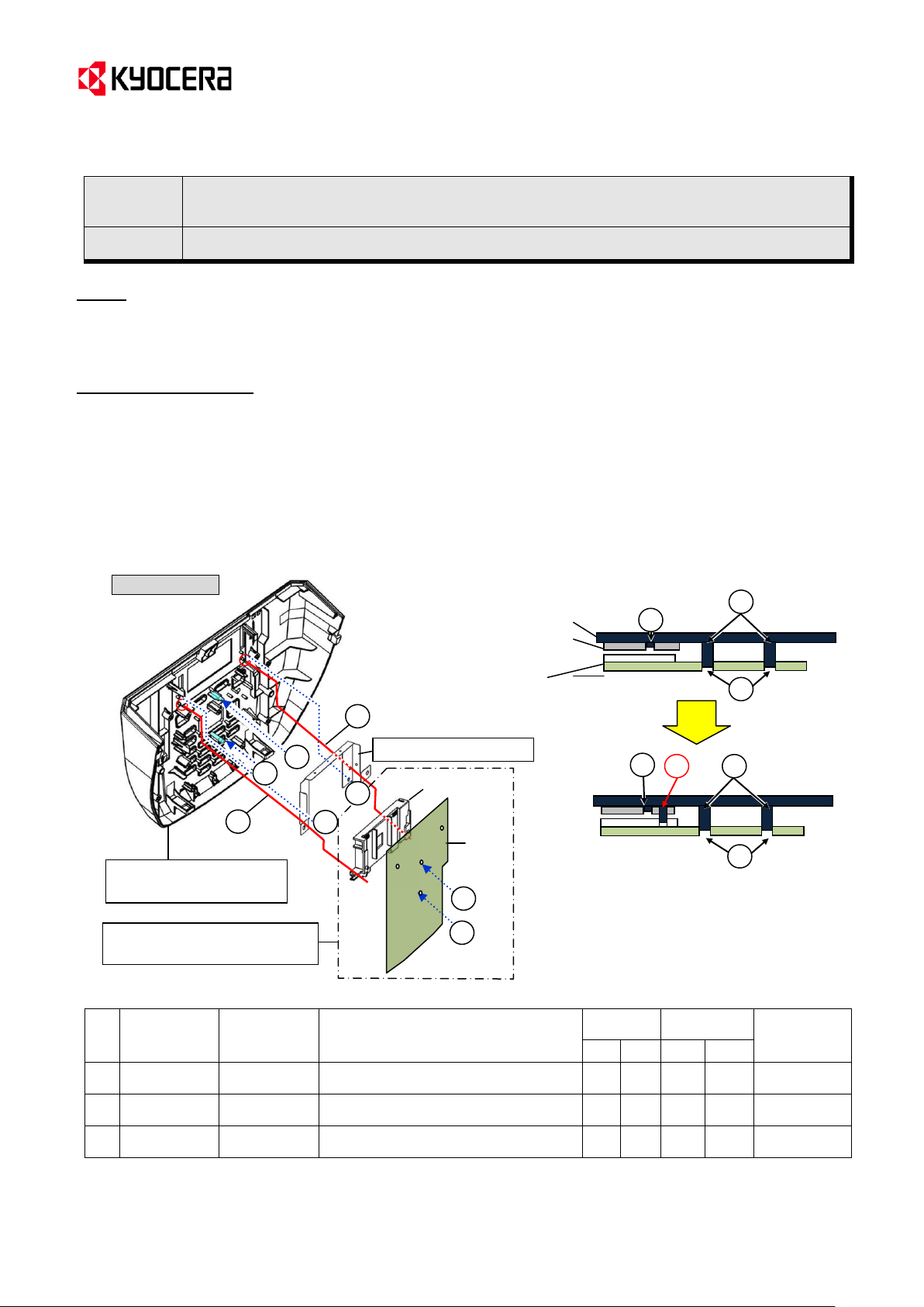
Z
Fixing of Z added
Y
X
(X to Z: Fixed by inserting the
boss to the added hole.)
X’
X
HOLDER LCD
Operation unit
X
Y
Y Z Z
(New)
COVER (No.1)
SHIELD (No.2)
HOLDER LCD
SHIELD LCD (No.2)
LCD PWB
Y
X
<Cross section>
X’
COVER OPERATION A
(No.1)
X’
X’
(Old)
PARTS PWB PANEL ASSY
SP (No.3)
Service Bulletin Ref. No. 2MN-0003 (C213)
<Date> August 30, 2012
Topic
The opeartion unit changed since the first production was changed again in order to improve the function.
Accordingly, some attention is required when replacing the parts. Please refer to [Field Measures] below.
Content of Changes
1) In order to prevent the location of the SHIELD LCD (No.2) and the HOLDER LCD (components of No.3)
from beting shifted, the shape of the following parts and the finxing methods were changed.
- COVER OPERATION A (No.1): The hole was added and the rib of the aperture for the LCD was
thickened.
- SHIELD LCD (No.2): The hole was added.
- HOLDER LCD (component of No.3): The hole and the rib were added (to improve the fitting margins).
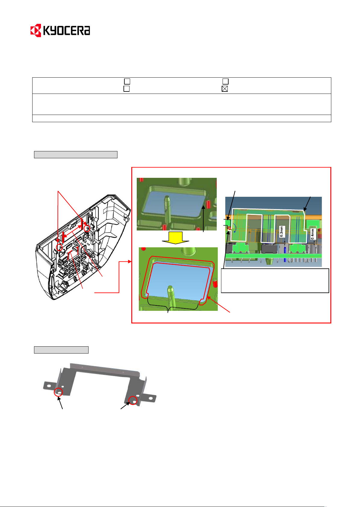
2) In order to secure the gap from the cross-shaped key, the rib at the aperture of the COVER OPERATION A
(No.1) close to the cross-shaped key was partly cut.
* When applying the new No.1 without physical compatibility with the machine before these changes, please apply the new No.2
and No.3.
KYOCERA Document Solutions Europe
Technical Customer Service Division (TCSD)
Page 2
(Page.2/3)
KMC’s Classification Entire Stock Rework In-Field modification at next visit
In-Field modification by case No modification necessary
Field Measure:
When applying the new COVER (No.1) to the machine before these changes, please apply the new No.2 and
No.3 at the same time.
Serial Nos. of the Affected Machines: Please refer to the page 3.
Two bosses were added to fix the
cover by inserting them into the
hole of HOLDER LCD with SHIELD
LCD (No.2) and LCD.
Thickened
Cut
(Cross section)
Rib partly cut to secure the gap
between the cross-shaped key and
COVER OPERATION A (No.1).
COVER OPERATION A (No.1)
Cross-shaped key
Two holes for the bosses of the COVER OPERATION A (No.1) were added.
Cut the rib
Rib
This rib remains unchanged.
(Old)
(New)
Service Bulletin Ref. No. 2MN-0003 (C213)
<Date> August 30, 2012
<Details of the shape change>
COVER OPERATION A (No.1)
---------------------------------------------------------------------------------------------------------------------------------------------------
SHIELD LCD (No.2)
KYOCERA Document Solutions Europe
Technical Customer Service Division (TCSD)
Page 3

(Page.3/3)
KDA
KDA 220VI
KDE
UTAX
KDAU
KDAS
KDKR
1102MN2US0
1102MN4US0
1102MN3NL0
1102MN3UT0
1102MN3AS0
1102MN3AX0
1102MN3KR0
NXW2800058
NXZ Next
NXX2800205
L4F Next
NXY2800011
L462800001
L47 Next
KDE
UTAX
1102N13NL0
1102N13UT0
NY22800198
L4G Next
LCD
PWB
Two holes for the bosses of COVER (No.1) added
Two ribs to fit the LCD added
<HOLDER LCD>
Service Bulletin Ref. No. 2MN-0003 (C213)
<Date> August 30, 2012
--------------------------------------------------------------------------------------------------------------------------------------------------HOLDER LCD (Not individually supplied) --- Component part of the PARTS PWB PANEL ASSY SP (No.3)
Serial Nos. of the Affected Machines
FS-C8650DN
FS-C8600DN
Technical Customer Service Division (TCSD)
KYOCERA Document Solutions Europe
 Loading...