

Page 1

ECOSYS FS-4300DN
ECOSYS FS-4200DN
ECOSYS FS-4100DN
ECOSYS FS-2100DN
ECOSYS FS-2100D
SERVICE
MANUAL
Published in August 2012
842LV110
2LVSM060
First Edition
Page 2

CAUTION
RISK OF EXPLOSION IF BATTERY IS REPLACED BY AN INCORRECT TYPE. DISPOSE
OF USED BATTERIES ACCORDING TO THE INSTRUCTIONS.
It may be illegal to dispose of this battery into the municipal waste stream. Check with your
local solid waste officials for details in your area for proper disposal.
ATTENTION
IL Y A UN RISQUE D’EXPLOSION SI LA BATTERIE EST REMPLACEE PAR UN MODELE
DE TYPE INCORRECT. METTRE AU REBUT LES BATTERIES UTILISEES SELON LES
INSTRUCTIONS DONNEES.
Il peut être illégal de jeter les batteries dans des eaux d’égout municipales. Vérifiez avec les
fonctionnaires municipaux de votre région pour les détails concernant des déchets solides
et une mise au rebut appropriée.
Notation of products in the manual
For the purpose of this service manual, products are identified by print speed at A4.
ECOSYS FS-4300DN : 60 ppm model
ECOSYS FS-4200DN : 50 ppm model
ECOSYS FS-4100DN : 45 ppm model
ECOSYS FS-2100DN : 40 ppm model (with Network)
ECOSYS FS-2100D : 40 ppm model (without Network)
Page 3

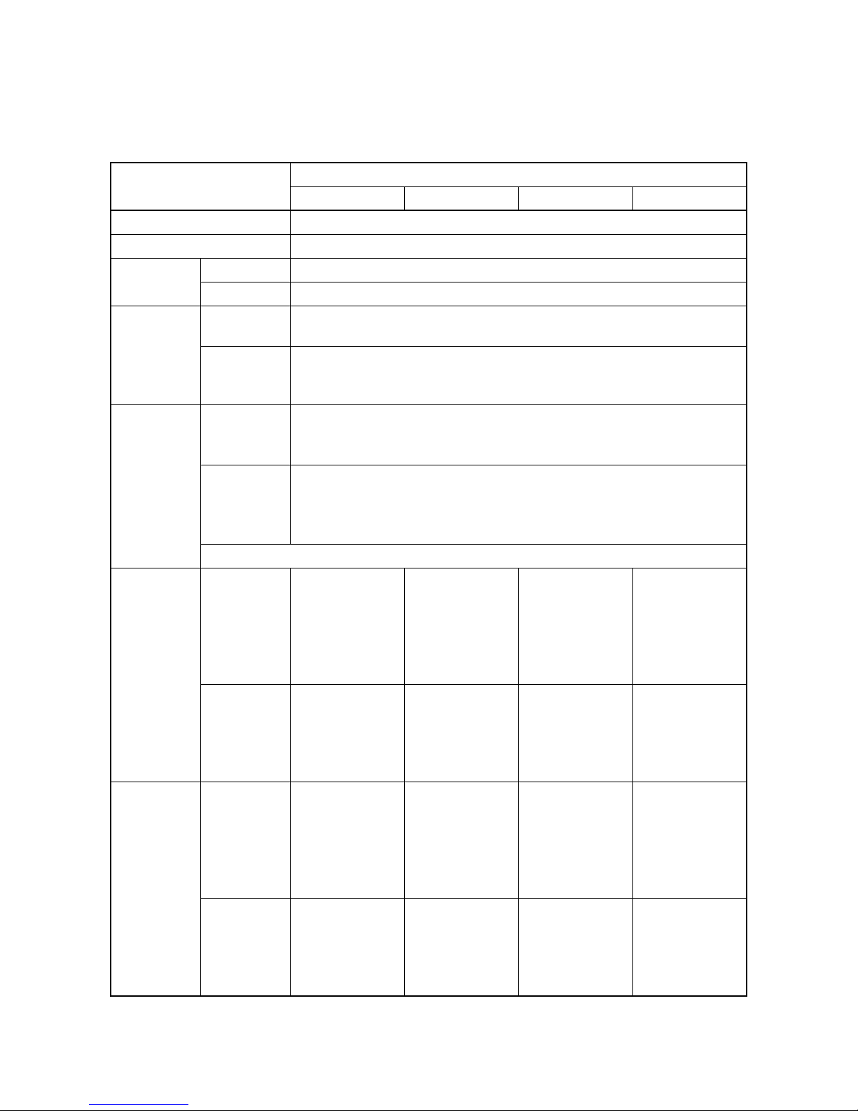
Revision history
Revision Date pages Revised contents
Page 4

This page is intentionally left blank.
Page 5

Safety precautions
This booklet provides safety warnings and precautions for our service personnel to ensure the safety of
their customers, their machines as well as themselves during maintenance activities. Service personnel
are advised to read this booklet carefully to familiarize themselves with the warnings and precautions
described here before engaging in maintenance activities.
Page 6
Safety warnings and precautions
Various symbols are used to protect our service personnel and customers from physical danger and
to prevent damage to their property. These symbols are described below:
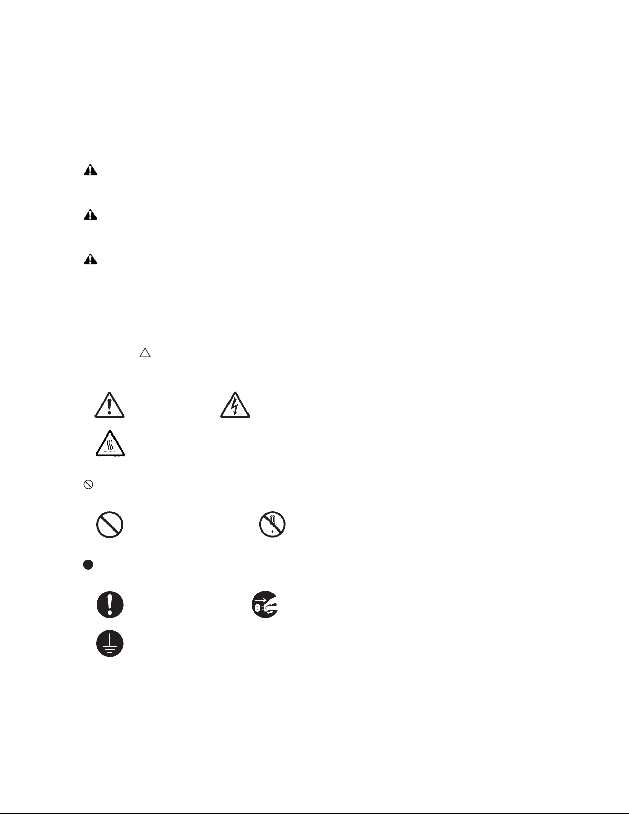
DANGER: High risk of serious bodily injury or death may result from insufficient attention to or incorrect
compliance with warning messages using this symbol.
WARNING: Serious bodily injury or death may result from insufficient attention to or incorrect compliance
with warning messages using this symbol.
CAUTION: Bodily injury or damage to property may result from insufficient attention to or incorrect com-
pliance with warning messages using this symbol.
Symbols
The triangle ( ) symbol indicates a warning including danger and caution. The specific point of attention is
shown inside the symbol.
General warning. Warning of risk of electric shock.
Warning of high temperature.
indicates a prohibited action. The specific prohibition is shown inside the symbol.
General prohibited action. Disassembly prohibited.
indicates that action is required. The specific action required is shown inside the symbol.
General action required. Remove the power plug from the wall outlet.
Always ground the copier.
Page 7

1. Installation Precautions
WARNING
• Do not use a power supply with a voltage other than that specified. Avoid multiple connections to
one outlet: they may cause fire or electric shock. When using an extension cable, always check that
it is adequate for the rated current. .....................................................................................................
• Connect the ground wire to a suitable grounding point. Not grounding the copier may cause fire or
electric shock. Connecting the earth wire to an object not approved for the purpose may cause
explosion or electric shock. Never connect the ground cable to any of the following: gas pipes, lightning rods, ground cables for telephone lines and water pipes or faucets not approved by the proper
authorities. ..........................................................................................................................................
CAUTION:
• Do not place the copier on an infirm or angled surface: the copier may tip over, causing injury. .........
• Do not install the copier in a humid or dusty place. This may cause fire or electric shock. .................
• Do not install the copier near a radiator, heater, other heat source or near flammable material. This
may cause fire. ...................................................................................................................................
• Allow sufficient space around the copier to allow the ventilation grills to keep the machine as cool
as possible. Insufficient ventilation may cause heat buildup and poor copying performance. ............
• Always handle the machine by the correct locations when moving it. .................................................
• Always use anti-toppling and locking devices on copiers so equipped. Failure to do this may cause
the copier to move unexpectedly or topple, leading to injury. ..............................................................
• Avoid inhaling toner or developer excessively. Protect the eyes. If toner or developer is accidentally
ingested, drink a lot of water to dilute it in the stomach and obtain medical attention immediately.
If it gets into the eyes, rinse immediately with copious amounts of water and obtain medical atten-
tion. .....................................................................................................................................................
• Advice customers that they must always follow the safety warnings and precautions in the copier’s
instruction handbook. .........................................................................................................................
Page 8
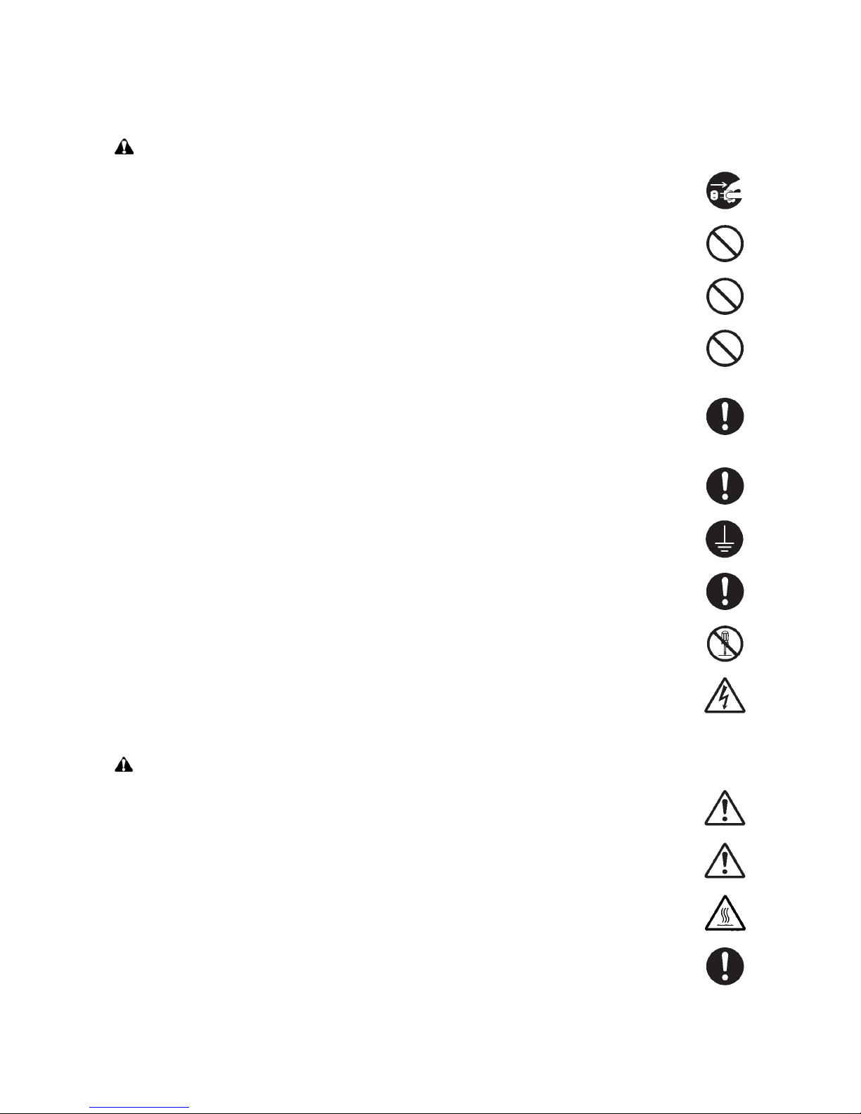
2. Precautions for Maintenance
WARNING
• Always remove the power plug from the wall outlet before starting machine disassembly. ................
• Always follow the procedures for maintenance described in the service manual and other related
brochures. ..........................................................................................................................................
• Under no circumstances attempt to bypass or disable safety features including safety mechanisms
and protective circuits. ........................................................................................................................
• Always use parts having the correct specifications. ............................................................................
• Always use the thermostat or thermal fuse specified in the service manual or other related brochure
when replacing them. Using a piece of wire, for example, could lead to fire or other serious acci-
dent. ...................................................................................................................................................
• When the service manual or other serious brochure specifies a distance or gap for installation of a
part, always use the correct scale and measure carefully. ..................................................................
• Always check that the copier is correctly connected to an outlet with a ground connection. ...............
• Check that the power cable covering is free of damage. Check that the power plug is dust-free. If it
is dirty, clean it to remove the risk of fire or electric shock. .................................................................
• Never attempt to disassemble the optical unit in machines using lasers. Leaking laser light may
damage eyesight. ...............................................................................................................................
• Handle the charger sections with care. They are charged to high potentials and may cause electric
shock if handled improperly. ...............................................................................................................
CAUTION
• Wear safe clothing. If wearing loose clothing or accessories such as ties, make sure they are safely
secured so they will not be caught in rotating sections. ......................................................................
• Use utmost caution when working on a powered machine. Keep away from chains and belts. ..........
• Handle the fixing section with care to avoid burns as it can be extremely hot. ..................................
• Check that the fixing unit thermistor, heat and press rollers are clean. Dirt on them can cause
abnormally high temperatures. ...........................................................................................................
Page 9
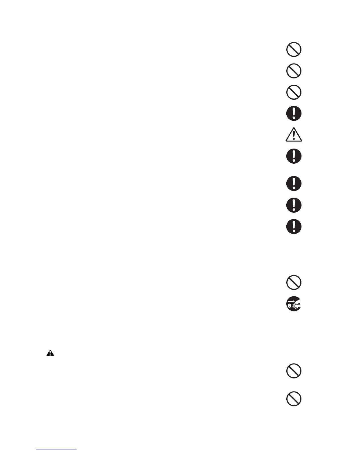
• Do not remove the ozone filter, if any, from the copier except for routine replacement. ......................
• Do not pull on the AC power cord or connector wires on high-voltage components when removing
them; always hold the plug itself. ........................................................................................................
• Do not route the power cable where it may be stood on or trapped. If necessary, protect it with a
cable cover or other appropriate item. ................................................................................................
• Treat the ends of the wire carefully when installing a new charger wire to avoid electric leaks. ..........
• Remove toner completely from electronic components. .....................................................................
• Run wire harnesses carefully so that wires will not be trapped or damaged. ......................................
• After maintenance, always check that all the parts, screws, connectors and wires that were
removed, have been refitted correctly. Special attention should be paid to any forgotten connector,
trapped wire and missing screws. .......................................................................................................
• Check that all the caution labels that should be present on the machine according to the instruction
handbook are clean and not peeling. Replace with new ones if necessary. .......................................
• Handle greases and solvents with care by following the instructions below: ......................................
· Use only a small amount of solvent at a time, being careful not to spill. Wipe spills off completely.
· Ventilate the room well while using grease or solvents.
· Allow applied solvents to evaporate completely before refitting the covers or turning the power
switch on.
· Always wash hands afterwards.
• Never dispose of toner or toner bottles in fire. Toner may cause sparks when exposed directly to
fire in a furnace, etc. ...........................................................................................................................
• Should smoke be seen coming from the copier, remove the power plug from the wall outlet immedi-
ately. ...................................................................................................................................................
3. Miscellaneous
WARNING
• Never attempt to heat the drum or expose it to any organic solvents such as alcohol, other than the
specified refiner; it may generate toxic gas. ........................................................................................
• Keep the machine away from flammable liquids, gases, and aerosols. A fire or an electric shock
might occur. ........................................................................................................................................
Page 10

This page is intentionally left blank.
Page 11

2LV/2L1/2L2/2MS/2MT
CONTENTS
1-1 Specifications
1-1-1 Specifications ........................................................................................................................ 1-1-1
1-1-2 Parts names .......................................................................................................................... 1-1-4
(1) Machine (front side)..........................................................................................................1-1-4
(2) Machine (rear side)........................................................................................................... 1-1-6
(3) Operation section ............................................................................................................. 1-1-7
1-1-3 Machine cross section ........................................................................................................... 1-1-8
(1) 60/50/45 ppm model......................................................................................................... 1-1-8
(2) 40 ppm model................................................................................................................... 1-1-9
1-2 Installation
1-2-1 Installation environment......................................................................................................... 1-2-1
1-2-2 Unpacking and installation..................................................................................................... 1-2-2
1-2-3 Install the expansion memory (option)................................................................................. 1-2-12
1-2-4 Install the memory card (SD card) (option).......................................................................... 1-2-13
1-2-5 Option composition.............................................................................................................. 1-2-14
1-3 Maintenance Mode
1-3-1 Service mode......................................................................................................................... 1-3-1
(1) Executing a service mode ................................................................................................ 1-3-1
(2) Description of service mode ............................................................................................. 1-3-2
(3) Printing an event log....................................................................................................... 1-3-15
1-4 Troubleshooting
1-4-1 Paper misfeed detection ........................................................................................................ 1-4-1
(1) Paper misfeed indication .................................................................................................. 1-4-1
(2) Paper misfeed detection condition ................................................................................... 1-4-1
(2-1) PF-320 (500 sheets Paper feeder)......................................................................... 1-4-1
(2-2) PF-315+ (Bulk Paper Feeder) ................................................................................ 1-4-2
1-4-2 Self-diagnostic function ......................................................................................................... 1-4-8
(1) Self-diagnostic function .................................................................................................... 1-4-8
(2) Self diagnostic codes........................................................................................................ 1-4-8
1-4-3 Image formation problems ................................................................................................... 1-4-24
(1) No image appears (entirely white).................................................................................. 1-4-25
(2) No image appears (entirely black).................................................................................. 1-4-25
(3) Image is too light. ........................................................................................................... 1-4-26
(4) The background is colored. ............................................................................................ 1-4-27
(5) White streaks are printed vertically................................................................................. 1-4-27
(6) Black streaks are printed vertically. ................................................................................ 1-4-28
(7) Streaks are printed horizontally. ..................................................................................... 1-4-28
(8) Spots are printed. ........................................................................................................... 1-4-28
(9) Image is blurred.............................................................................................................. 1-4-29
(10) Paper is wrinkled. ........................................................................................................... 1-4-29
(11) Offset occurs. ................................................................................................................. 1-4-29
(12) Part of image is missing. ................................................................................................ 1-4-29
(13) Fusing is loose................................................................................................................ 1-4-30
(14) Image is out of focus. ..................................................................................................... 1-4-30
1-4-4 Electric problems ................................................................................................................. 1-4-31
1-4-5 Mechanical problems........................................................................................................... 1-4-35
Page 12

2LV/2L1/2L2/2MS/2MT
1-5 Assembly and disassembly
1-5-1 Precautions for assembly and disassembly........................................................................... 1-5-1
(1) Precautions....................................................................................................................... 1-5-1
(2) Drum unit .......................................................................................................................... 1-5-1
(3) Toner ................................................................................................................................ 1-5-1
(4) How to tell a genuine Kyocera toner container................................................................. 1-5-2
1-5-2 Outer covers .......................................................................................................................... 1-5-3
(1) Detaching and refitting the top cover................................................................................ 1-5-3
(2) Detaching and refitting the inlet cover and slot cover....................................................... 1-5-3
(3) Detaching and refitting the right upper cover.................................................................... 1-5-4
(4) Detaching and refitting the right lower cover .................................................................... 1-5-4
(5) Detaching and refitting the rear left cover......................................................................... 1-5-5
(6) Detaching and refitting the left upper cover...................................................................... 1-5-5
(7) Detaching and refitting the left lower cover ...................................................................... 1-5-6
(8) Detaching and refitting the rear cover .............................................................................. 1-5-6
1-5-3 Paper feed section................................................................................................................. 1-5-8
(1) Detaching and refitting the paper feed roller .................................................................... 1-5-8
(2) Detaching and refitting the retard roller ............................................................................ 1-5-8
(3) Detaching and refitting the MP paper feed pulley............................................................. 1-5-9
1-5-4 Developer section ................................................................................................................ 1-5-13
(1) Detaching and refitting the developer unit ...................................................................... 1-5-13
1-5-5 Drum section ....................................................................................................................... 1-5-15
(1) Detaching and refitting the drum unit.............................................................................. 1-5-15
(2) Detaching and refitting the chager roller unit.................................................................. 1-5-15
1-5-6 Transfer/separation section ................................................................................................. 1-5-16
(1) Detaching and refitting the transfer roller assembly ....................................................... 1-5-16
(2) Detaching and refitting the separation needle unit ......................................................... 1-5-17
1-5-7 Optical section ..................................................................................................................... 1-5-18
(1) Detaching and refitting the laser scanner unit ................................................................ 1-5-18
1-5-8 Fuser section ....................................................................................................................... 1-5-19
(1) Detaching and refitting the fuser unit.............................................................................. 1-5-19
1-5-9 ejection section .................................................................................................................... 1-5-21
(1) Detaching and refitting the ejection unit ......................................................................... 1-5-21
1-5-10 PWBs................................................................................................................................... 1-5-22
(1) Detaching and refitting the main PWB............................................................................ 1-5-22
(2) Detaching and refitting the engine PWB......................................................................... 1-5-22
(3) Detaching and refitting the relay-L PWB ........................................................................ 1-5-24
(4) Detaching and refitting the power source PWB.............................................................. 1-5-25
(5) Detaching and refitting the high voltage PWB ................................................................ 1-5-26
(6) Detaching and refitting the operation PWB .................................................................... 1-5-28
1-5-11 Others .................................................................................................................................. 1-5-29
(1) Detaching and refitting the main driving motor unit ........................................................ 1-5-29
(2) Detaching and refitting the paper feed driving motor unit............................................... 1-5-30
(3) Detaching and refitting the power source fan motor....................................................... 1-5-30
(4) Direction of installing the principal fan motors ................................................................ 1-5-31
1-6 Requirements on PWB Replacement
1-6-1 Upgrading the firmware ......................................................................................................... 1-6-1
1-6-2 Remarks on PWB replacement ............................................................................................. 1-6-2
(1) Engine PWB ..................................................................................................................... 1-6-2
Page 13

2LV/2L1/2L2/2MS/2MT
2-1 Mechanical Construction
2-1-1 Paper feed/conveying section ............................................................................................... 2-1-1
(1) Cassette paper feed section............................................................................................. 2-1-1
(2) MP tray paper feed section............................................................................................... 2-1-2
(3) Conveying section ............................................................................................................ 2-1-3
2-1-2 Drum section ......................................................................................................................... 2-1-4
(1) Charger roller unit............................................................................................................. 2-1-4
(2) Cleaning unit..................................................................................................................... 2-1-5
2-1-3 Developer section .................................................................................................................. 2-1-6
2-1-4 Optical section ....................................................................................................................... 2-1-7
(1) Laser scanner section ...................................................................................................... 2-1-7
2-1-5 Transfer/Separation section .................................................................................................. 2-1-8
2-1-6 Fuser section ......................................................................................................................... 2-1-9
2-1-7 Eject/Feedshift section ........................................................................................................ 2-1-11
2-1-8 Duplex conveying section....................................................................................................2-1-13
2-2 Electrical Parts Layout
2-2-1 Electrical parts layout ............................................................................................................ 2-2-1
(1) PWBs................................................................................................................................ 2-2-1
(2) Switches and sensors....................................................................................................... 2-2-3
(3) Motors............................................................................................................................... 2-2-5
(4) Clutches and others.......................................................................................................... 2-2-7
2-3 Operation of the PWBs
2-3-1 Main PWB (MPWB) ............................................................................................................... 2-3-1
2-3-2 Engine PWB (EPWB) ............................................................................................................ 2-3-6
2-3-3 Power source PWB (PSPWB) ............................................................................................. 2-3-13
2-3-4 Relay-L PWB (R-LPWB)...................................................................................................... 2-3-15
2-3-5 High voltage PWB (HVPWB)............................................................................................... 2-3-18
2-4 Appendixes
2-4-1 Appendixes ............................................................................................................................ 2-4-1
(1) Maintenance kits............................................................................................................... 2-4-1
(2) Repetitive defects gauge .................................................................................................. 2-4-2
(3) Firmware environment commands ................................................................................... 2-4-3
(4) Wiring diagram (60/50/45 ppm model) ........................................................................... 2-4-11
(5) Wiring diagram (40ppm model) ...................................................................................... 2-4-13
Installation Guide
500 sheets paper feeder
2000 sheets bulk paper feeder
Expanded HDD (SSD)
IEEE1284 Interface
Network interface
Wireless LAN interface
Page 14

2LV/2L1/2L2/2MS/2MT
This page is intentionally left blank.
Page 15
1-1 Specifications
1-1-1 Specifications
2LV/2L1/2L2/2MS/2MT
Item
Specifications
60 ppm 50 ppm 45 ppm 40 ppm
Typ e Desktop
Printing method Electrophotography by semiconductor laser
Paper
weight
Cassette 60 to 120 g/m
MP tray 60 to 220 g/m
Cassette
Plain, Recycled, Bond, Color (Colour), Preprinted, Letterhead,
Prepunched, Rough, High quality, Custom 1 to 8
2
2
, 230 g/m
2
(Postcard)
Paper
type
MP tray
Plain, Recycled, Bond, Color (Colour), Preprinted, Letterhead,
Prepunched, Rough, High quality, Label, Transparency, Postcard, Vellum,
Thick, Envelope, Custom 1 to 8
Legal, Oficio II, Mexican Oficio, Letter, Executive, Statement, Folio, A4,
Cassette
B5(JIS), A5, B6 *1, A6 *1, Return postcard *1, B5(ISO), C5, DL *1, 16K,
Custom
Paper
size
MP tray
Legal, Oficio II, Mexican Oficio, Letter, Executive, Statement, Folio, A4,
B5(JIS), A5, B6, A6, Return postcard, Postcard, B5(ISO), C5, Commercial
#10, DL, Commercial #9, Monarch, Commercial #6-3/4, Youkei4, Youkei2,
16K, Custom
*1: 60/50/45 ppm model only
[Simplex]
50/52
- /42
40
27
27
Printing
speed
A4/Letter
-/Legal
B5R
A5R
A6R
60/62
- /50
48
32
32
(ppm)
Full speed
[Duplex]
A4/Letter
-/Legal
B5R
A5R
43/44
- /25
34
23
36/37
- /21
28
19
45/47
- /38
36
23
23
32/33
- /16
25
16
40/42
- /33
33
22
22
20/21
- /16.5
16.5
11
[Simplex]
A4/Letter
-/Legal
B5R
Printing
speed
A5R
A6R
(ppm)
Half speed
[Duplex]
A4/Letter
-/Legal
B5R
A5R
30/31
- /25
24
16
16
21.5/22
- /12.5
17
11.5
1-1-1
25/26
- /21
20
13.5
13.5
18/18.5
- /10.5
14
9.5
22.5/23.5
- /19
18
11.5
11.5
16/16.5
- /8
12.5
8
20/21
- /17
16.5
11
11
10/10.5
- /8
8
5.5
Page 16

2LV/2L1/2L2/2MS/2MT
Item
Specifications
60 ppm 50 ppm 45 ppm 40 ppm
Resolution
First print time
Fine1200, Fast1200(KIR), 600dpi(KIR) , 300dpi
9.0 s or less
(A4, feed from cassette)
Warm-up
time
(22 °C/
71.6 °F,
60% RH)
Paper
capacity
Output tray
capacity
Power on/
Off mode/
25 s or less
Sleep mode
Low power
mode
-
Cassette 500 sheets (80g/m
MP tray 100 sheets (80 g/m
Facedown
500 sheets (67g/m
Faceup 100 sheets (67g/m
20 s or less 15 s or less 15 s or less
2
)
2
)
2
)
2
)
Photoconductor a-Si drum (diameter 30 mm)
Image write system Semiconductor laser
Charging system Contact charger roller method
Developer system
Mono component dry developing method
Toner replenishing: Automatic from the toner container
Transfer system Transfer roller method
Separation system Small diameter separation, dischager needle (DC bias)
Cleaning system Counter blade cleaning + cleaning roller
Charge erasing system Exposure by cleaning lamp (LED)
250 sheets
2
(67g/m
)
-
Heat and pressure fusing with the heat roller and the press roller
Fusing system
Heat source: halogen heater
Abnormally high temperature protection devices: thermostat
CPU PowerPC465, ARM7/ARM9 PowerPC465 *1
Main memory 256 MB / 1280 MB (Standard / Max) *2
Windows XP, Windows XP Professional,
Windows Server 2003, Windows Server 2003 x64 Edition,
Operating system
Windows Vista x86 Edition, Windows Vista x64 Edition,
Windows 7 x86 Edition, Windows 7 x64 Edition,
Windows Server 2008, Windows Server 2008 x64 Edition,
Apple Macintosh OS X
USB device interface connector: 1 (USB 2.0)
Interface
Standard
Option
USB host interface connector: 2 (USB 2.0)
Network interface connector: 1 (10BASE-T/100BASE-TX/1000BASE-T) *3
eKUIO slot: 1
Page description language PRESCRIBE
Emulation PCL6, KPDL3, XPS, Line printer, IBM Proprinter X24E, EPSON LQ-850
1-1-2
Page 17
2LV/2L1/2L2/2MS/2MT
Item
Tem p e r a t u r e 10 to 32.5 °C/50 to 90.5 °F
Operating
environment
Humidity 15 to 80% RH
Altitude 2,500 m/8,202 ft or less
Brightness 1,500 lux or less
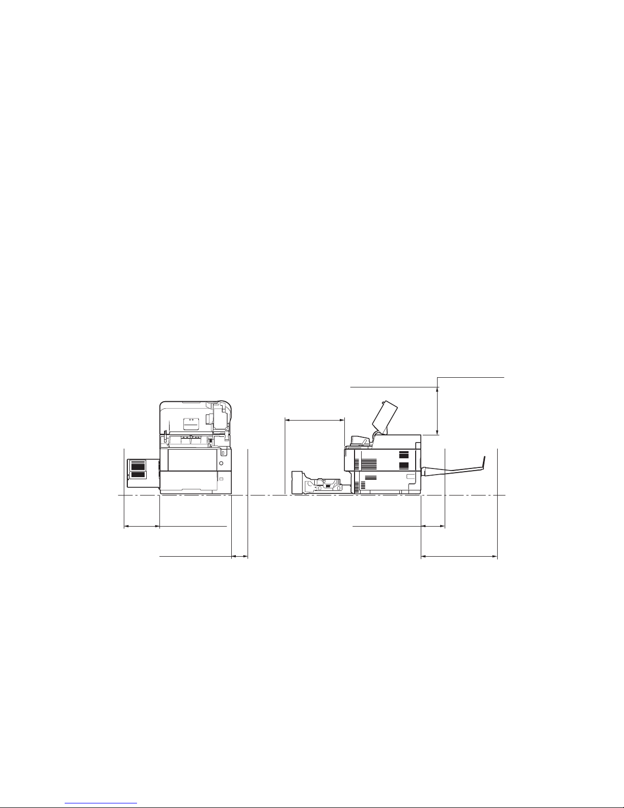
Dimensions (W × D × H)
Weight
(with toner container)
Space required (W × D)
Power source
120 V AC, 60 Hz
220 - 240 V AC, 50/60 Hz
Options
Specifications
60 ppm 50 ppm 45 ppm 40 ppm
380 × 416 × 320 mm / 14 15/16” × 16 3/8 “× 12 1/4”
380 × 416 × 285
14 15/16” × 16 3/
8 “× 11 1/4”
14.6 kg / 32.2 lb
13.5kg/29.8lb
380 × 593 mm / 14 15/16” × 23 3/8” (using MP tray)
380 × 1138 mm / 14 15/16” × 44 13/16”
(using 2000 sheets paper feeder + Faceup tray)
380 × 799 mm /
14 15/16” × 31 7/
16”
(using 2000
sheets paper
feeder)
more than 10.0 A
more than 6.0 A
500 sheets paper feeder, 2000 sheets bulk paper feeder, Faceup tray *4,
Expanded HDD (SSD), IEEE1284 Interface, Network interface,
Wireless LAN interface, Expanded memory, SD card,
Card Authentication Kit, IC card reader, Data Security Kit(E), USB keyboard,
UG-33(Thin print)
*1: 40 ppm (without Network) model ;
*2: 40 ppm (without Network) model ; 128 MB / 1152 MB (Standard / Max)
*3: 40 ppm (without Network) model ; Network interface connector : 0
*4: 60/50/45 ppm model only
NOTE: These specifications are subject to change without notice.
1-1-3
Page 18
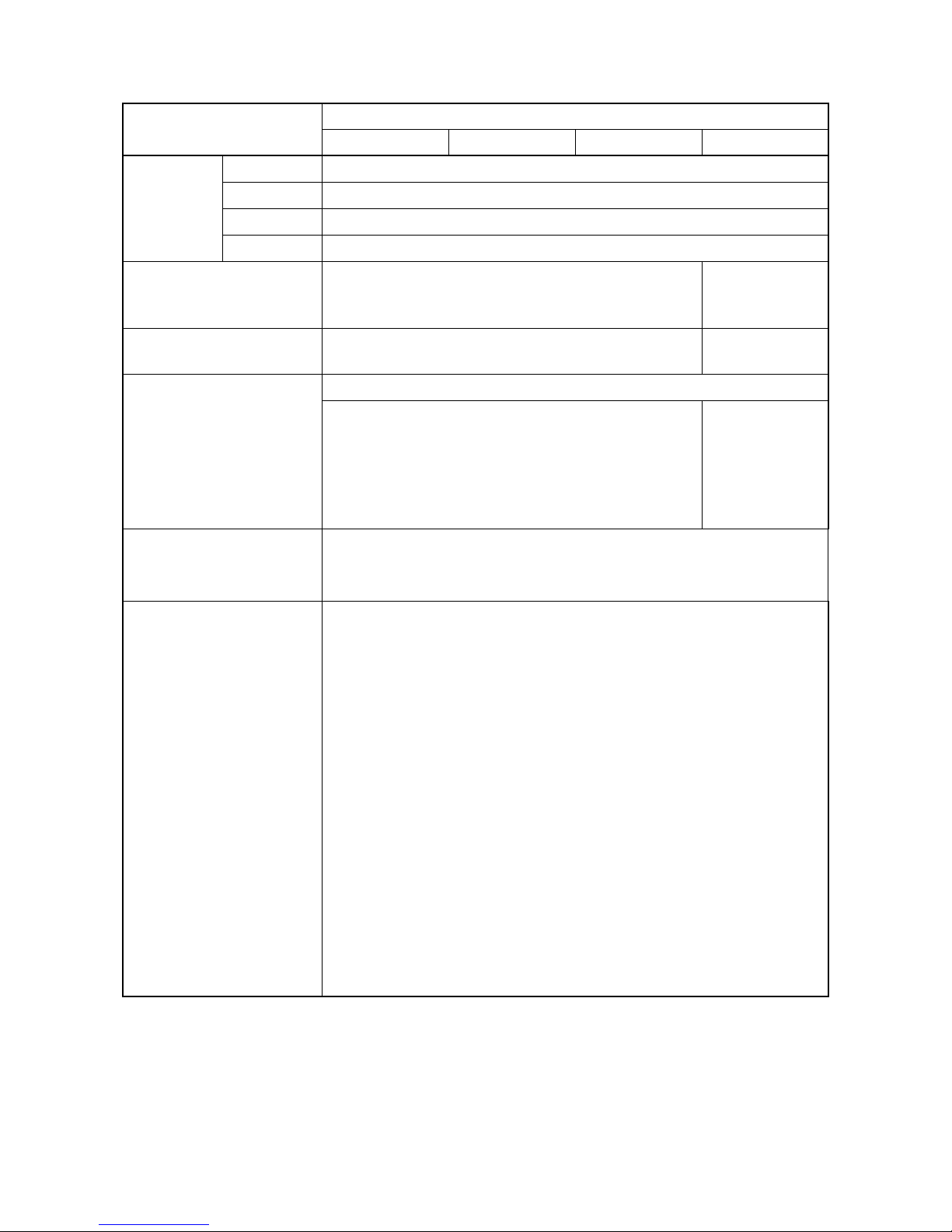
1-1-2 Parts names
1. Machine
2. Power switch
3. Cassette
4. Paper size label
5. Paper width guides
6. Paper length guide
7. USB memory slot
8. Top cover
9. Toner container
10. Lock lever (Toner container)
11. Developer unit
(1) Machine (front side)
11
2LV/2L1/2L2/2MS/2MT
8
9
3
5
1
10
7
2
6
5
4
Figure 1-1-1
1-1-4
Page 19
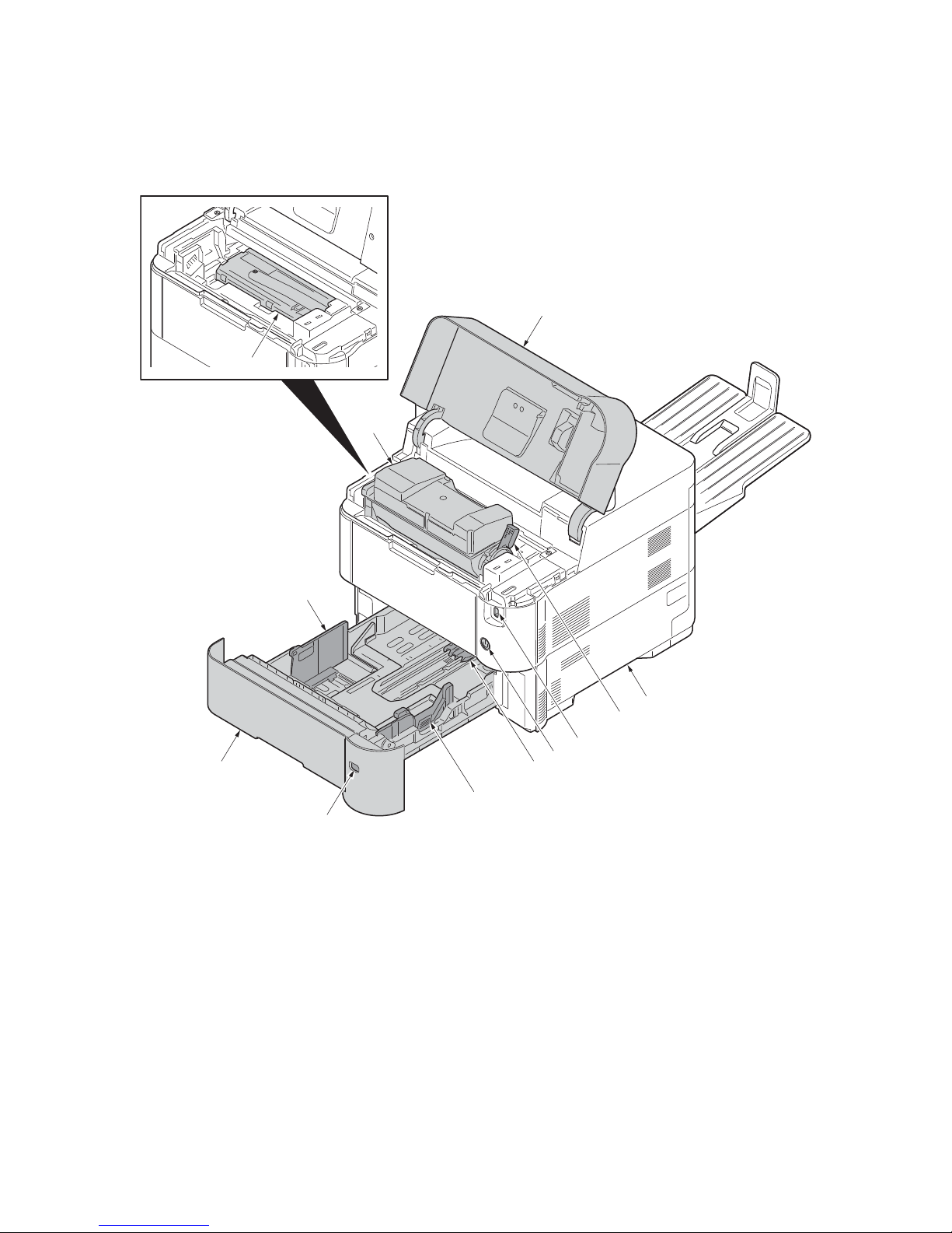
2LV/2L1/2L2/2MS/2MT
12. Operation panel
13. MP (multi purpose) tray
14. MP middle tray
15. MP top tray
16. MP Paper width guides
17. MP paper feed roller
18. Left cover
19. Waste toner box
20. Top tray (facedown)
21. Eject roller
18
21
19
20
12
17
16
15
14
13
16
Figure 1-1-2
1-1-5
Page 20
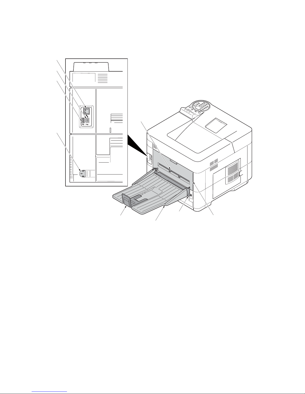
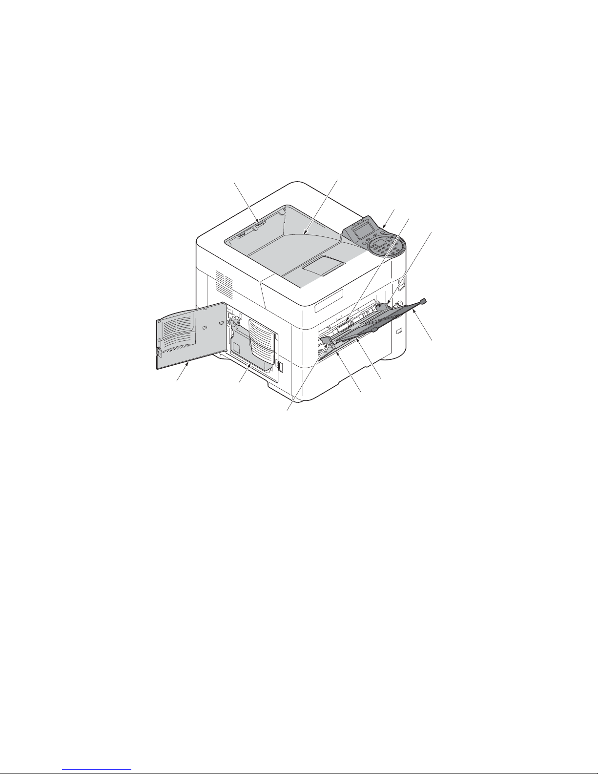
(2) Machine (rear side)
22. Rear cover
23. Faceup roller *1
24. Tray attachment plate *2
25. Faceup tray *2
26. Paper stopper *2
27. Network interface connector *3
28. USB interface connector
29. USB port
30. Power cord connector
*1: 60/50/45 ppm model only
*2: 60/50/45 ppm model only (Option)
*3: Except 40 ppm model
(without Network)
27
28
29
30
2LV/2L1/2L2/2MS/2MT
23
26
24
25
Figure 1-1-3
1-1-6
22
Page 21
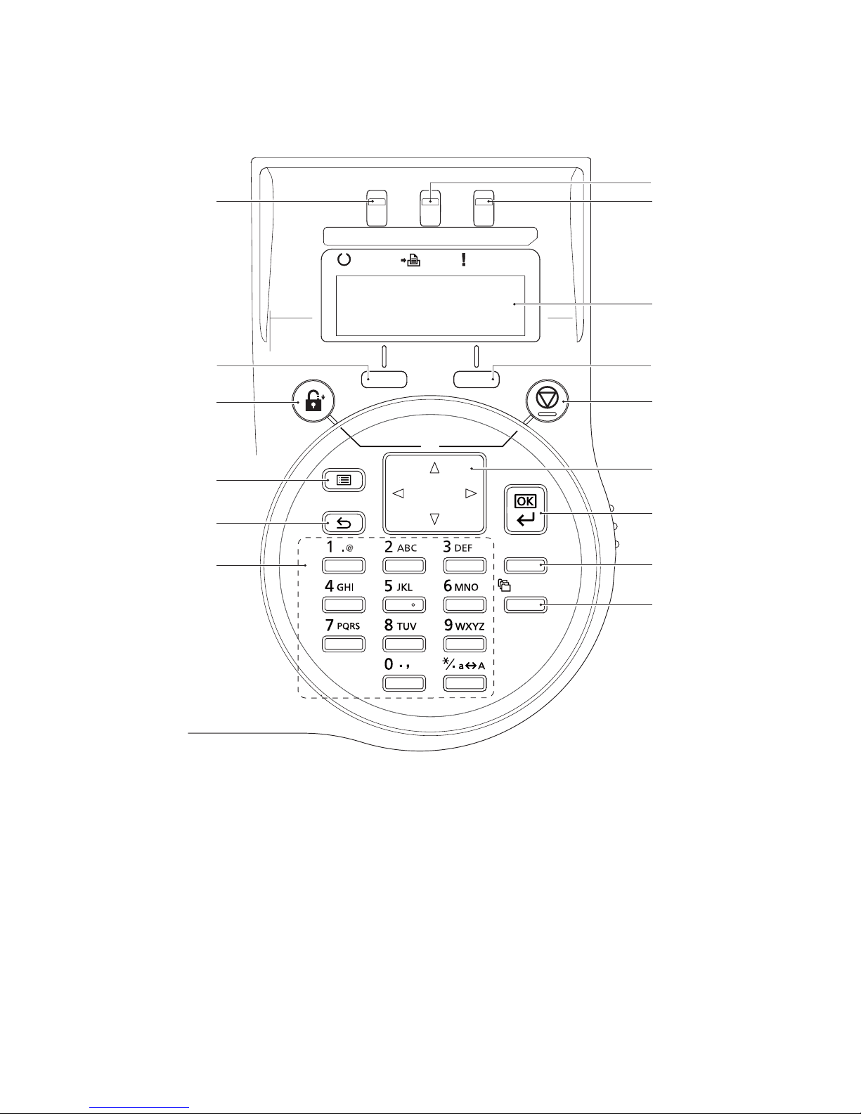
(3) Operation section
RReadyeady DataData
AttentioAttention
Logout
Cancel
BackBack
ClearClear
Documement Box
Menuenu
39
37
31
35
40
43
42
38
34
33
36
32
44
45
41
31. Ready indicator
32. Data indicator
33. Attention indicator
34. Message display
35. Left select key
36. Right select key
37. Logout key
38. Cancel key
39. Menu key
40. Back key
41. Numeric keys
42. Cursor keys
43. OK key
44. Clear key
45. Document box key
2LV/2L1/2L2/2MS/2MT
Figure 1-1-4
1-1-7
Page 22

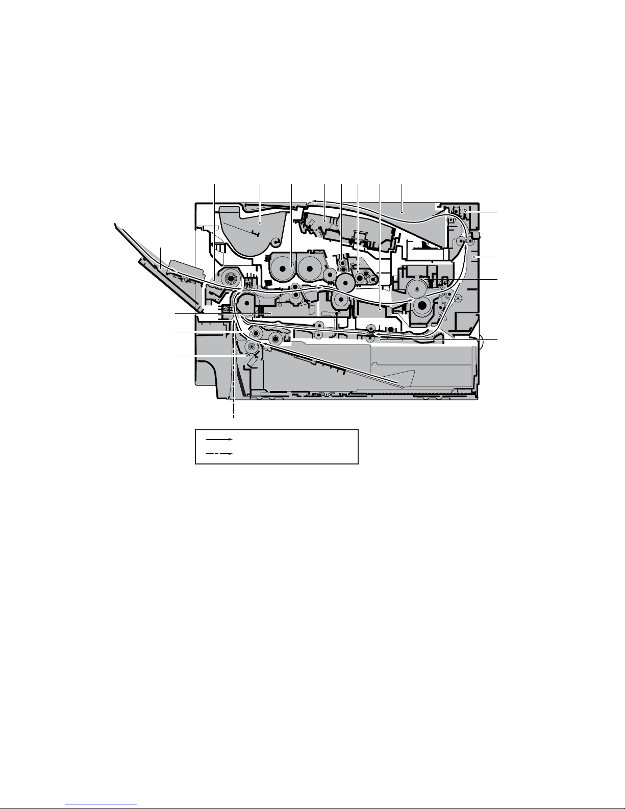
1-1-3 Machine cross section
1. Cassette
2. Cassette paper feed section
3. Paper feed conveying section
4. MP tray
5. MP tray paper feed section
6. Toner container
7. Developer unit
8. Laser scanner unit (LSU)
9. Charger roller unit
10. Drum unit
11. Transfer/Separation section
12. Eject tray (facedown)
13. Eject section
14. Eject conveying section
15. Fuser unit
16. Duplex conveyning section
17. Faceup tray (option)
(1) 60/50/45 ppm model
5
7
96 128
2LV/2L1/2L2/2MS/2MT
10 11
13
4
14
15
3
2
1
Paper path
Paper path (Option)
Figure 1-1-5
16
17
1-1-8
Page 23
(2) 40 ppm model
1. Cassette
2. Cassette paper feed section
3. Paper feed conveying section
4. MP tray
5. MP tray paper feed section
6. Toner container
7. Developer unit
8. Laser scanner unit (LSU)
9. Charger roller unit
10. Drum unit
11. Transfer/Separation section
12. Eject tray (facedown)
13. Eject section
14. Eject conveying section
15. Fuser unit
16. Duplex conveyning section
2LV/2L1/2L2/2MS/2MT
5
7
10 1196 128
13
4
14
15
3
2
16
1
Paper path
Paper path (Option)
Figure 1-1-6
1-1-9
Page 24

2LV/2L1/2L2/2MS/2MT
This page is intentionally left blank.
1-1-10
Page 25
2LV/2L1/2L2/2MS/2MT
1-2 Installation
1-2-1 Installation environment
1. Temperature: 10 to 32.5°C/50 to 90.5°F
2. Humidity: 15 to 80% RH
3. Power supply: 120 V AC, 12.0 A
220 - 240 V AC, 6.5 A
4. Power supply frequency: 50 Hz ±2%/60 Hz ±2%
5. Installation location
Avoid direct sunlight or bright lighting. Ensure that the photoconductor will not be exposed to direct sunlight or other strong light when removing paper jams.
Avoid locations subject to high temperature and high humidity or low temperature and low humidity; an
abrupt change in the environmental temperature; and cool or hot, direct air.
Avoid places subject to dust and vibrations.
Choose a surface capable of supporting the weight of the machine.
Place the machine on a level surface (maximum allowance inclination: 1°).
Avoid air-borne substances that may adversely affect the machine or degrade the photoconductor, such
as mercury, acidic of alkaline vapors, inorganic gasses, NOx, SOx gases and chlorine-based organic solvents.
Select a well-ventilated location.
6. Allow sufficient access for proper operation and maintenance of the machine.
300mm or more
11
13/16”
or more
100mm or more
15/16”
3
or more
500mm or more
19
11/16”
or more
*1: Without the faceup tray
*2: With the faceup tray (60/50/45 ppm model)
Figure 1-2-1
200mm or more
7
7/8”
or more *1
400mm or more
3/4”
or more
15
400mm or more
15
3/4”
or more *2
1-2-1
Page 26

1-2-2 Unpacking and installation
Unpacking
1. Outer case
2. Inner case
3. Bottom pad R
4. Bottom pad L
5. Machine cover (740 × 700)
6. Machine
7. Upper pad R
8. Upper pad L
9. Operation guide
10. Operation sheets Assy *1
11. Waste toner bottle
12. Power cord
*1: Except 240V model
2LV/2L1/2L2/2MS/2MT
6
11
12
10
5
4
3
9
8
7
2
Caution: Place the machine on a level surface.
1
Figure 1-2-2
1-2-2
Page 27
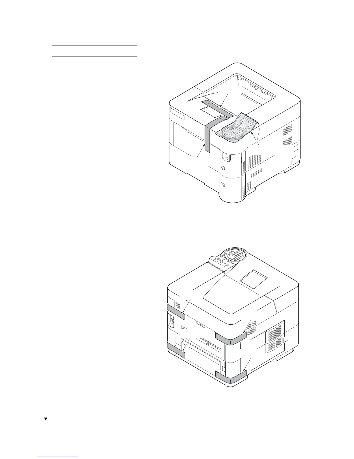
Removing the tapes and pads
1. Remove two tapes.
2. Remove the protection sheet.
2LV/2L1/2L2/2MS/2MT
Ta pe
Protection sheet
Ta pe
3. Remove four tapes.
Figure 1-2-3
Tape
Tape
Tape
Tape
Figure 1-2-4
1-2-3
Page 28

(60/50/45 ppm model only)
Tape
Top cover
Spacer
Installing the toner container
4. Open the top cover.
5. Remove the tape and the spacer.
2LV/2L1/2L2/2MS/2MT
1. Remove the container label by
removing the tape.
Caution: Check the contents of the
container label and remove a container.
Figure 1-2-5
Container label
Tape
Figure 1-2-6
1-2-4
Page 29
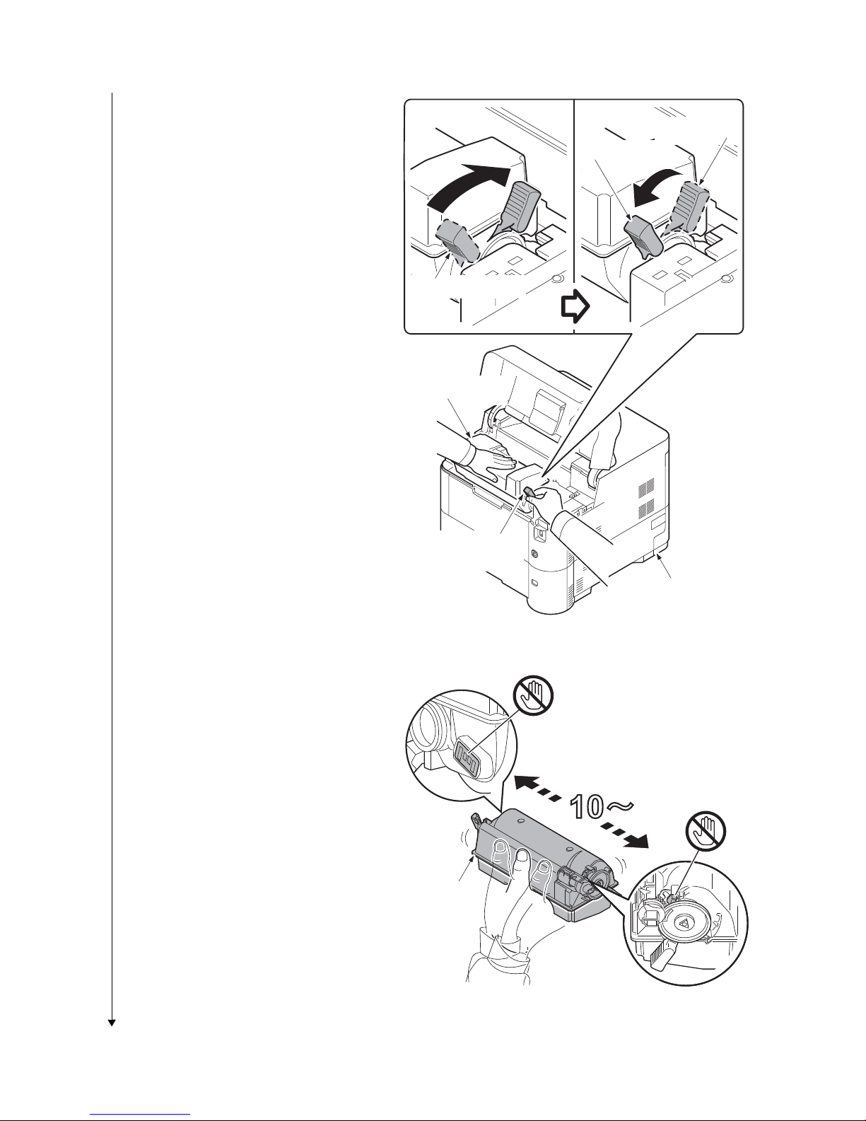
2LV/2L1/2L2/2MS/2MT
2. Rotate the toner container lock lever to
the lock position and then remove the
toner container from the printer by
returning it to the unlock position.
Lock position
Unlock position
Shipment position
Toner container
3. Shake the turned toner container 10
times or more as shown in the figure in
order to distribute the toner evenly
inside the container.
Caution:Do not press too firmly on the
center of the toner container or touch
the toner feed slot or the terminal parts.
4. Set the toner container to the printer
and then turn the toner container lock
lever to the lock position.
5. Close the top cover.
Toner container
lock lever
Printer
Figure 1-2-7
Terminal parts
Toner feed slot
To ne r
container
Figure 1-2-8
1-2-5
Page 30

1. Openthe left cover.
Installing the waste toner box
Waste toner box
Cap
Left cover
Setting of the fuser pressure release lever (40 ppm model only)
2. Open the cap of the waste toner box.
3. Install the waste toner box.
4. Close the left cover.
2LV/2L1/2L2/2MS/2MT
1. Open the rear cover.
2. Push the release lever down for
changing the lever position to a normal
position from a shipment position.
3. Close the rear cover.
Figure 1-2-9
Release lever
(Shipment position)
Release lever
(Normal position)
Rear cover
Figure 1-2-10
1-2-6
Page 31

1. Pull the cassette from the printer out.
Loading paper
(40 ppm model only)
Botom plate
Cassette
Cassette size dial
Cassette size window
Paper width guide
Paper width guide
Lock lever
(40 ppm model only)
2. Push the bottom plate down.
(Common)
3. Turn the cassette size dial so that the
size of the paper you are going to use
appears in the cassette size window.
2LV/2L1/2L2/2MS/2MT
Figure 1-2-11
4. Push the lock lever on the left side
guide and slide to the desired paper
size.
Figure 1-2-12
Figure 1-2-13
1-2-7
Page 32

5. Push the lock lever and slide the paper
(Legal/Folio)
Paper length guide
Extension cassette
Lock button
Paper
Muximum
line
length guide to the desired paper size.
If you are going to set paper that is longer than A4, pull out the extension cassettes pushing the lock lbutton one by
one and adjust them to the desired
paper size.
2LV/2L1/2L2/2MS/2MT
6. Fan the media (paper/transparencies),
then tap it on a level surface to avoid
media jams or skewed printing.
7. Slide the paper into the paper cassette.
8. Insert the cassette into the slot in the
printer. Push it straight in as far as it will
go.
Figure 1-2-14
Figure 1-2-15
1-2-8
Page 33

1. Rotate the operation panel ring in the
Replace the operation panel sheet (except 240V AC model)
Operation panel
sheet
Operation panel
cover
Operation panel
ring
counterclockwise direction.
2. Remove the operation panel cover.
3. Replace it to the operation panel sheet
of the corresponding language.
4. Refit all the removed parts.
2LV/2L1/2L2/2MS/2MT
5. Stick the language sheet of the corresponding language.
Figure 1-2-16
Language sheet
Figure 1-2-17
1-2-9
Page 34
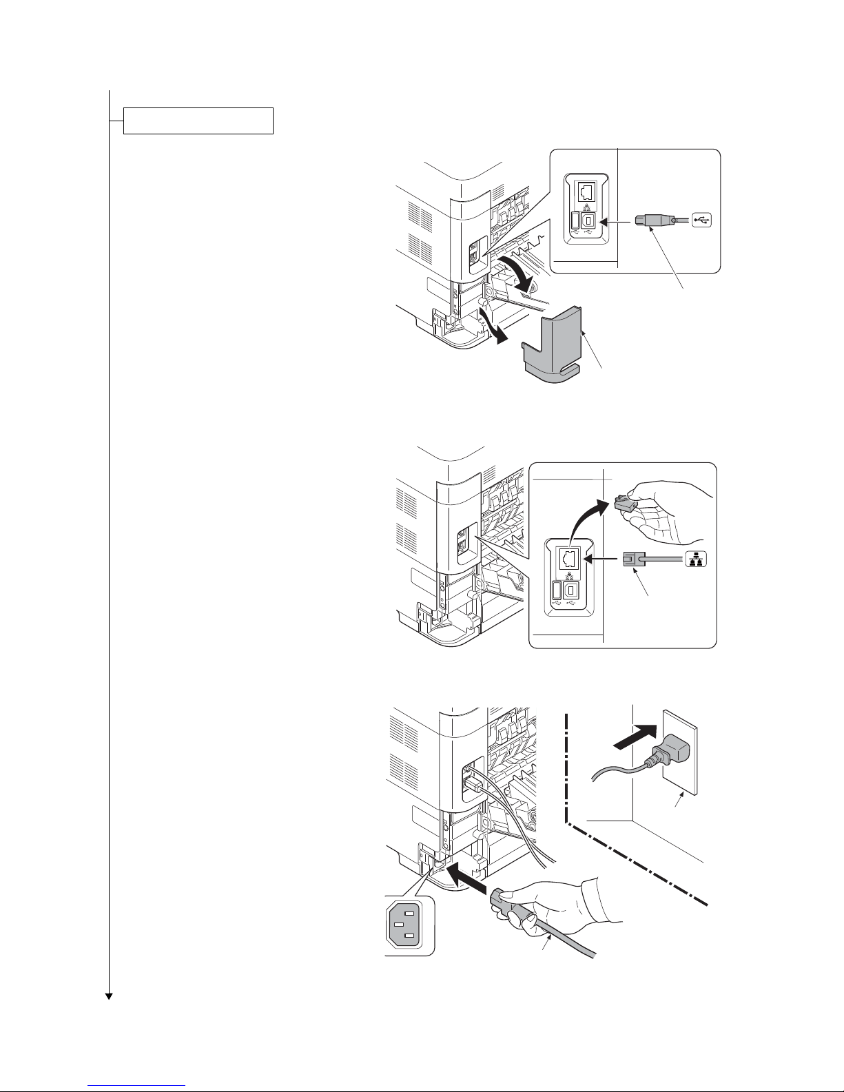
1. Remove the inlet cover.
Connecting the cable
Network
interface cable
Power cord
Wall outlet
2. Open the rear cover.
3. Connect the USB interface cable to the
printer and PC.
2LV/2L1/2L2/2MS/2MT
USB interface cable
Inlet cover
Figure 1-2-18
4. Connect the network interface cable to
the printerand network.
5. Connect the power cord to the printer
and the wall outlet.
6. Refit the inlet cover.
7. Close the rear cover.
Figure 1-2-19
Figure 1-2-20
1-2-10
Page 35

2LV/2L1/2L2/2MS/2MT
Power on
Setting the language
Printout the status page
Completion of the machine installation
8. Press the power switch and then check
the lighting up of ready indicator.
9. Installing the printer driver (refer to
operation guide).
Power switch
1. Press the menu key.
2. Select [Device Common] using the cursor up/down keys.
3. Press the OK key.
4. Select [Language] using the cursor up/down keys.
5. Press the OK key.
6. Select the language to set using the cursor up/down keys.
7. Press the OK key.
ON
Ready indicator
ON
Figure 1-2-21
1. Press the menu key.
2. Select [Report Print] using the cursor up/down keys.
3. Press the OK key.
4. Select [Status Page] using the cursor up/down keys.
5. Press the OK key.
6. Select the [YES] using the left select key.
7. [Accepted] is displayed and the page will be printed.
8. Press the menu key.
1-2-11
Page 36

1-2-3 Install the expansion memory (option)
Procedure
1. Remove the inlet cover.
2. Remove the slot cover.
3. Unplug the power cable.
Caution: Do not insert or remove main
PWB assembly while machine power is
on.
Doing so may cause damage to the
machine and the main PWB.
2LV/2L1/2L2/2MS/2MT
Slot cover
Inlet cover
4. Remove five screws and then remove
the main PWB assembly.
5. Aligning the cutouts of the memory
module with the matching keys of the
socket, carefully plug the memory module into the memory socket until it clicks
in place.
6. Then, push down the memory module
to secure.
7. Refit the main PWB assembly and the
screws.
8. Refit the covers.
9. Plug the printer into a power outlet.
10. Print a status page to check the memory expansion. (See page 1-3-2)
If memory expansion has been properly
performed, information on the installed
memory is printed with the total memory
capacity has been increased.
Standard memory capacity 256 MB. *1
Figure 1-2-22
Expansion
memory
Main PWB
Assembly
Memory socket
Screw
Screw
Screw
Screw
*1: 40 ppm (without Metwork); 128MB
Figure 1-2-23
1-2-12
Page 37

1-2-4 Install the memory card (SD card) (option)
Procedure
1. Remove the main PWB assembly from
the machine. (SeePage 1-2-12)
2. SD card is inserted in a SD card slot.
Maximum memory capacity 32 GB.
3. Remove the main PWB assmbly and
the covers.
Main PWB assembly
SD card slot
2LV/2L1/2L2/2MS/2MT
Figure 1-2-24
SD card
1-2-13
Page 38

1-2-5 Option composition
2LV/2L1/2L2/2MS/2MT
USB Flash Memory
Faceup Output Tray PT-320
(60/50/45 ppm model only)
Expansion Memory
(DIMM 256 MB/
512 MB/1 GB)
Gigabit Ethernet Board
IB-50
SD Memory Card
SDHC Memory Card
SSD HD-6
Attchment PB-325
Bulk Paper Feeder PF-315+
Paper Feeder PF-320
IC card reader
Thin Print Kit UG-33
1-2-14
Wireless LAN
interface card
IB-51
Parallel
Interface Card
IB-32
USB KeyboardData security kit (E) Card Authentication Kit (B)
Page 39

2LV/2L1/2L2/2MS/2MT
1-3 Maintenance Mode
1-3-1 Service mode
The machine is equipped with a maintenance function which can be used to maintain and service the
machine.
(1) Executing a service mode
Start
Press the Menu key.
Select [Adjust/Maint.] using the cursor
up/down keys and press the OK key.
Select [Service Setting] using the cursor
up/down keys and press the OK key.
The selected service mode is run.
Press the Menu key.
End
The Mode Selection Menu appears.
The Adjust/Maintenance menu appears.
The Service Setting menu appears.
1-3-1
Page 40

(2) Description of service mode
Service items Description
Service Status Printing a status page for service purpose
Description
Prints a status page for service purpose. The status page includes various settings and
service cumulative.
Purpose
To acquire the current printing environmental parameters and cumulative information.
Method
1. Enter the Service Setting menu.
2. Select [Status Page] using the cursor up/down keys.
3. Press the OK key.
4. Select the [YES] using the left select key.
[Accepted] is displayed and two pages will be printed.
2LV/2L1/2L2/2MS/2MT
1-3-2
Page 41

Service items Description
Service status page (1)
2LV/2L1/2L2/2MS/2MT
Service Status Page
Printer
(1)
Firmware version 2LV_2000.000.000 2012.04.19
Controller Information
Memory status
(7)
Standard Size
(8)
Option Slot
(9)
Total Size
Time
(10)
Local Time Zone
(11)
Date and Time
(12)
Time Server
Installed Options
(13)
Paper feeder2
(14)
Paper feeder3
Paper feeder4
(15)
Paper feeder5 Not Installed
(16)
Bulk Feeder
(17)
Memory card Installed
(18)
SSD Installed
(19)
Card Authentication Kit (B) Installed
(20)
Security Kit(E)
(21)
Data Security Kit (E)
UG-33 Installed
(22)
USB Keyboard Connected
(23)
USB Keyboard Type US-English
(24)
(25)
Print Coverage
(26)
Average(%)
K: 1.10
(27)
Last Page (%)
128.0 KB
128.0 KB
256.0 KB
+01:00 Tokio
19/06/2010 16:39
10.183.53.13
Installed
Installed
Not Installed
Not Installed
Installed
/ Usage Page(A4/Letter Conversion)
/ 1111111.11
1.00
(2)
2012/04/19 16:39
(3) (4) (5)
[XXXXXXXX] [XXXXXXXX] [XXXXXXXX]
.
.
.
.
.
.
.
.
.
.
.
.
.
.
.
.
.
.
.
.
.
.
.
.
.
.
PDF mode
Y5 00
(28) (29)
FRPO Status
User Top Margin
User Left Margin
A1+A2/100
A3+A4/100
.
.
.
.
0.00
0.00
1
Figure 1-3-1
1-3-3
RP Code
1234 5678 9012
5678 9012 3456
9012 3456 7890
3456 7890 1234
(6)
[XXXXXXXXXXXXXXXX]
Page 42

Service items Description
Service status page (2)
Service Status Page
Printer
2LV/2L1/2L2/2MS/2MT
2012/04/19 16:39
Firmware version 2LV_2000.000.000 2012.04.19
Engine Information
(30)
NVRAM Version
(31)
MAC Address
1/2
(34) (35)
(36)
100/100
(37)
0/0/0/0/0/0/0/
0/0/0/0/0/0/0/
(38)
0/0/0/0/
(39)
0000000/0000000/0000000/0000000/0000000/0000000/0000000/0000000/
(40)
0000000/0000000/0000000/0000000/
F00/U00/0/0/0/30/30/70/70/00/00/00/abcde/1/0/1/
_1F31225_1F31225
00:C0:EE:D0:01:0D
[XXXXXXXX] [XXXXXXXX] [XXXXXXXX]
Send Information
(32)
(33)
Date and Time
Address
10/06/19 16:39
(41)(42)(43)(44)(45)(46)(47)(48)(49)(50)(51)(52)(53)(54)(55)(56)
0000/0000/0000/0000/0000/0000/0000/0000/0000/0000/0000/0000/0000/0000/0000/
(57)
0000/0000/0000/0000/0000/0000/0000/0000/0000/0000/
12345678/11223344/00001234abcd567800001234abcd5678/01234567890123456789012345678901/0008/00/07
(58)
t/
(59)
00/
(60)
00000000000000000000000000000000/00000000000000000000000000000000/
0000000000000000000000000000000000000000000000000000000000000000/
(63)
00000000/00000000/00000000/00000000/00000000/00000000/00000000/00000000/00000000/00000000/00000000/
(64)
00000000/00000000/00000000/00000000/00000000/00000000/00000000/00000000/00000000/00000000/00000000/
00000000/00000000/00000000/00000000/00000000/00000000/00000000/00000000/00000000/00000000/00000000/
00000000/00000000/00000000/00000000/00000000/00000000/00000000/00000000/00000000/00000000/00000000/
00000000/00000000/00000000/00000000/00000000/00000000/00000000/00000000/00000000/00000000/00000000/
00000000/00000000/00000000/00000000/00000000/00000000/00000000/00000000/00000000/00000000/00000000/
[ ] [ ] [ ] [ ] [ ]
(65)
[2LV_81BR.001.010]
0/3/
(69)
(77)
(78)
(79)
(80)
(81)
(67)(68)
1/1/0 2010 /12/15 12:34:56
1/5/
(70)(71)
20/100/1/1/5
1/2/3/4/5/6/7/8/9/10/11/12/13/14/15/16
0.00/0.00/0.00/0.00/0.00/0.00/0.00/0.00/0.00/0.00/0.00/0.00/0.00/0.00/0.00/0.00/
0.00/0.00/0.00/0.00/0.00/0.00/0.00/0.00/0.00/0.00/0.00/0.00/0.00/0.00/0.00/0.00/
0.00/
0.00/0.00/0.00/0.00/0.00/0.00/0.00/0.00/0.00/0.00/0.00/0.00/0.00/0.00/0.00/0.00/
0/
(82)
ABCD/ABCDEFGHIJ/
(66)
(72)(73)(74)(75)(76)
(83)(84)
(61)(62)
1-3-4
2
Figure 1-3-2
[XXXXXXXXXXXXXXXX]
Page 43

Service items Description
No. Description Supplement
(1) Firmware version -
(2) System date -
(3) Engine soft version -
(4) Engine boot version -
(5) Operation panel mask version -
(6) Machine serial number -
(7) Standard memory size -
(8) Optional memory size -
(9) Total memory size -
(10) Local time zone -
(11) Report output date Day/Month/Year hour:minute
(12) NTP server name -
(13) Presence or absence of the
optional paper feeder 1
Installed/Not Installed
(14) Presence or absence of the
optional paper feeder 2
Installed/Not Installed
(15) Presence or absence of the
optional paper feeder 3
Installed/Not Installed
(16) Presence or absence of the
optional paper feeder 4
Installed/Not Installed
(17) Presence or absence of the
optional bulk feeder
Installed/Not Installed
(18) Presence or absence of the
optional memory card
Installed/Not Installed
(19) Presence or absence of the
optional SSD
Installed/Not Installed
(20) Presence or absence of the
optional Card Authentication
Kit(B)
Installed/Not Installed/Trial
(21) Presence or absence of the
optional Security Kit(E)
Installed/Not Installed
(22) Presence or absence of the
optional UG-33
Installed/Not Installed
(23) The connection state of an
optional USB Keyboard
Connected/Not Connected
(24) Displays setting of optional USB
Keyboard
US English/US English with Euro/German/French
Detail of service status page
1-3-5
2LV/2L1/2L2/2MS/2MT
Page 44
Service items Description
No. Description Supplement
(25) Page of relation to the A4/Letter -
(26) Average coverage for printer Black
(27) Coverage on the final output
page
-
(28) FRPO setting -
(29) RP Code Code the engine software version and the date of
update.
Code the main software version and the date of
update.
Code the engine software version and the date of the
previous update.
Code the main software version and the date of the
previous update.
(30) NV RAM version _ 1F3 1225 _ 1F3 1225
(a) (b) (c) (d) (e) (f)
(a) Consistency of the present software version and
the database
_ (underscore): OK
* (Asterisk): NG
(b) Database version
(c) The oldest time stamp of database version
(d) Consistency of the present software version and
the ME firmware version
_ (underscore): OK
* (Asterisk): NG
(e) ME firmware version
(f) The oldest time stamp of the ME database version
Normal if (a) and (d) are underscored, and (b) and (e)
are identical with (c) and (f).
(31) Mac address -
(32) The last sent date and time -
(33) Transmission address -
(34) Destination information -
(35) Area information -
(36) Margin settings Top margin/Left margin
(37) Top offset for each paper source MP tray/Paper feeder 1/Paper feeder 2/
Paper feeder 3/Paper feeder 4/Duplex/Page rotation
(38) Left offset for each paper source MP tray/Paper feeder 1/Paper feeder 2/
Paper feeder 3/Paper feeder 4/Duplex/Page rotation
(39) Margin/Page length/Page width
settings
Top margin integer part/Top margin decimal part/
Left margin integer part/Left margin decimal part/
Page length integer part/Page length decimal part/
Page width integer part/Page width decimal part
Detail of service status page
1-3-6
2LV/2L1/2L2/2MS/2MT
Page 45

Service items Description
No. Description Supplement
(40) Life counter (The first line) Machine life/MP tray/Cassette/Paper feeder 1/
Paper feeder 2/Paper feeder 3/Paper feeder 4/Duplex
Life counter (The second line) Bulk Feeder counter/Drum counter K/
Developer counter K/Maintenance kit counter
(41)
Panel lock information F00: OFF
F01: Partial Lock 1
F02: Partial Lock 2
F03: Partial Lock 3
F04: Full Lock
(42) USB information U00: Not installed/U01: Full speed/U02: Hi speed
(43)
Paper handling information 0: Paper source unit select/1: Paper source unit
(44) Black and white printing double
count mode
0: All single counts
3: Folio, Single count, Less than 330 mm (length)
(45) Billing counting timing -
(46) Temperature (machine inside) -
(47) Temperature (machine outside) -
(48) Relative temperature
(machine outside)
-
(49) Absolute temperature
(machine outside)
-
(50) XLI calibration information -
(51) Beam A/BD synchronous fine-
tuning value
-
(52) Beam B/BD synchronous fine-
tuning value
-
(53) Fixed assets number -
(54) Job end judgment time-out time -
(55) Job end detection mode -
(56) PRESCRIBE environmental
reset
-
(57) Media type attributes
1 to 28 (Not used: 18, 19, 20)
Weight settings Fuser settings
0: Light 0: High
1: Normal 1 1: Middle
2: Normal 2 2: Low
3: Normal 3 3: Vellum
4: Heavy 1 Duplex settings
5: Heavy 2 0: Disable
6: Heavy 3 1: Enable
7: Extra Heavy
2LV/2L1/2L2/2MS/2MT
1-3-7
Page 46

Service items Description
No. Description Supplement
(58) RFID information Product (OEM/maker) / destination code / a toner
name / lot number / toner capacity / toner empty information / number of times of toner refilling
(59) Toner install mode information 0:OFF
t:ON
(60) Drum status -
(61) Drum surface potential -
(62) Drum density -
(63) LSU light volume distribution -
(64) DRT parameter coefficient -
(65) Soft version of the optional
paper feeder
Paper feeder 1/Paper feeder 2/Paper feeder 3
Paper feeder 4
(66) Version of the optional message -
(67) Altitude 0: Standard
1: High altitude 1
2: High altitude 2
(68) Charger roller correction 1 to 5
(69) Data Sanitization details result -
(70) Toner Low setting 0:Invalid
1: Effective
(71) Toner Low detection level 0 to 100(%)
(72) Number of page that swept out
at any time (SP1)
1 to 65535
(73) Number of page that swept out
at instancy (SP2)
1 to 65535
(74) The practice standard printing
rate of development TC (SGE)
0 to 15
(75) The practice standard printing
rate according to area TC
(SDR)
0 to15
(76) The number of times of enforce-
ment of the development TC
-
(77) The number of times of enforce-
ment according to area
-
2LV/2L1/2L2/2MS/2MT
1-3-8
Page 47

Service items Description
No. Description Supplement
(78) The last page printing rate of
each area
0.00 to 100.00(%)
(79) The average printing rate of
each area
0.00 to 100.00(%)
(80) The average printing rate for the
1000 past
0.00 to 100.00(%)
(81) The average printing rate for the
1000 past of each area
0.00 to 100.00(%)
(82) ErP application 0: ErP Un-Applying mode
1: ErP Application mode
(83) Drum ID -
(84) Drum serial number -
Code conversion
ABCDEFGH I J
0123456789
2LV/2L1/2L2/2MS/2MT
1-3-9
Page 48

Service items Description
LS-4300DN SN:SPL8307597 Counter:1135
Network Status Printing a status page for network
Description
Prints a status page for network.
Execution is possible only the model with network.
Purpose
To acquire the detailed network setting information.
Method
1. Enter the Service Setting menu.
2. Select [Network Status Page] using the cursor up/down keys.
3. Press the OK key.
4. Select the [YES] using the left select key.
[Accepted] is displayed and Network status page will be printed.
Test Page Printing a test page
Description
The test page is printed with halftones.
Purpose
To check the activation of the developer and drum units.
2LV/2L1/2L2/2MS/2MT
Method
1. Enter the Service Setting menu.
2. Select [Test Page] using the cursor up/down keys.
3. Press the OK key.
4. Select the [YES] using the left select key.
[Accepted] is displayed and Test page will be printed.
Figure 1-3-3
1-3-10
Page 49

Service items Description
Maintenance Counter reset for the maintenance kit
Description
The "Install MK" message means that maintenance kit should be replaced at fixed pages
of printing. The interval counter must be manually reset using this service item.
Maintenance kit MK-3102 (for 120 V ) (40 ppm) :300,000 images
Maintenance kit MK-3132 (for 120 V ) (60/50/45 ppm) :500,000 images
Maintenance kit MK-3100 (for 230 V ) (40 ppm) :300,000 images
Maintenance kit MK-3130 (for 230 V ) (60/50/45 ppm) :500,000 images
Maintenance kit includes the following units:
Drum unit
Developer unit
Transfer roller assembly
Fuser unit
Paper feed roller assembly
Retard roller assembly
Purpose
To reset the life counter for maintenance kit.
2LV/2L1/2L2/2MS/2MT
Method
Drum unit (see page 1-5-15)
Developer unit (see page 1-5-13)
Transfer roller assembly (see page 1-5-16)
Fuser unit (see page 1-5-19)
Paper feed roller assembly (see page 1-5-8)
Retard roller assembly (see page 1-5-8)
Method
1. Enter the Service Setting menu.
2. Select [Maintenance] using the cursor up/down keys.
3. Press the OK key.
4. Select the [YES] using the left select key.
[Completed] is displayed.
The counter for each component is reset immediately.
Note:
Occurrences of resetting the maintenance kits are recorded on the service status page
or event log in number of pages at which the maintenance kit was replaced (see page 13-2, page 1-3-17 ). This may be used to determine the possibility that the counter was
errorneously or unintentionally reset.
1-3-11
Page 50

Service items Description
New Developer
Initializing the developing unit (toner install mode)
Description
The new developing unit is shipped from the factory with no toner contained. The developing unit can be automatically replete with toner when a toner container is installed onto
it and the printer is turned on. However, because the toner reservoir in the developing
unit has a large capacity, it requires a lengthy period of time until a substantial amount of
toner has been fed to get the printer ready. (A new developing unit needs approximately
200 g for triggering the sensor inside.)
Purpose
To execute when the developing unit has been replaced.
Method
1. Enter the Service Setting menu.
2. Select [New Developer] using the cursor up/down keys.
3. Press the OK key.
4. Select the [YES] using the left select key.
[Accepted] is displayed.
The toner installation is performed when power is turned on and off.
NOTE: Toner supply is stopped when toner installation mode is performing.
2LV/2L1/2L2/2MS/2MT
Auto Drum
Refresh
Automatic drum surface refreshing
Description
The drum surface refreshing operation is normally performed when the power is turned
on to the printer or during warm-up when the printer is recovering from the Sleep mode,
but even then only at those times that the temperature/humidity sensor detects the drum
surface to be in a state of dew condensation. By using this mode, it is possible to force
the drum surface refreshing operation to be performed automatically at a predetermined
period of time, regardless of the status detected by the temperature/humidity sensor.
Purpose
To prevent bleeding of the output image when the printer's operating environment is one
of high humidity.
Method
1. Enter the Service Setting menu.
2. Select [Auto Drum Refresh] using the cursor up/down keys.
3. Press the OK key.
4. Select the desire mode (Off/Short/Standard/Long) using the cursor up/down keys.
5. Press the OK key. The new value is set.
1-3-12
Page 51

Service items Description
Drum Drum surface refreshing
Description
Rotates the drum approximately 3 minutes with toner lightly on the overall drum using
the high-voltage output control. The cleaning blade in the drum unit scrapes toner off the
drum surface to clean it.
Purpose
To clean the drum surface when image failure occurs due to the drum. This mode is
effective when dew condensation on the drum occurs.
Method
1. Enter the Service Setting menu.
2. Select [Drum] using the cursor up/down keys.
3. Press the OK key.
4. Select the [YES] using the left select key.
Drum surface refreshing will start.
2LV/2L1/2L2/2MS/2MT
Write Data
Write data (USB memory data write)
Description
To write data into a USB memory.
Execution is possible only when a USB memory is detected.
Method
Install the USB memory before attempting to write data.
1. Enter the Service Setting menu.
2. Select [Write Data] using the cursor up/down keys.
3. Press the OK key.
4. Select the [YES] using the left select key.
5. [Data waiting] is displayed and the printer waits for data to be written.
6. When the data is sent, [Processing] appears and the data is written to USB memory.
When data writing ends, the display returns to [Ready].
1-3-13
Page 52

Service items Description
Altitude adj. Setting altitude adjustment
Description
Sets the altitude adjustment mode.
Purpose
Used when print quality deteriorates in an installation at the altitude of 1,500 meters or
higher.
Method
1. Enter the Service Setting menu.
2. Select [Altitude Adj.] using the cursor up/down keys.
3. Press the OK key.
4. Select [Normal], [High 1] or [High 2] using the cursor up/down keys.
5. Press the OK key. The setting is set.
MC Setting main charger output
Description
Sets the main charger output.
Execution is possible only when the altitude adjustment mode is set to [Normal].
Purpose
Execute when the image density declines, dirt of a background or an offset has
occurred.
2LV/2L1/2L2/2MS/2MT
Method
1. Enter the Service Setting menu.
2. Select [MC] using the cursor up/down keys.
3. Press the OK key.
4. Select [1] to [5] using the cursor up/down keys.
5. Press the OK key. The setting is set.
1-3-14
Page 53

(3) Printing an event log
Service items Description
Printing an
event log
Printing an event log (EVENT LOG)
Description
Prints a history list of occurrences of paper jam, self-diagnostics, toner replacements,
etc.
Purpose
To allow machine malfunction analysis based on the frequency of paper misfeeds, self
diagnostic errors and replacements.
Method
1. Connect the USB or network cable between machine and PC (network).
2. Remove the inlet cover and connect the power cord.
Network cable
2LV/2L1/2L2/2MS/2MT
USB cable
Inlet cover
Power cord
Figure 1-3-4
3. Refit the inlet cover.
4. Turn the main power switch on. Make sure the machine is ready.
5. Send the following PRESCRIBE command sequence from the PC to the machine.
!R!KCFG"ELOG";EXIT;
6. A sheet of event log will be printed.
Completion
1-3-15
Page 54

Service items Description
Printing an
Remarks: Details of configurations (See above 5.)
event log
Notes on Connecting to USB
(1)Save the PRESCRIBE commands above as a text file in the PC.
(2)Select the Sharing tab of the printer properties and share the printer.
(3)Select a USB port in the Port tab. (Specify the printer name for sharing.)
(4)From the DOS Prompt, execute the following command line:
copy file-name\\computer-name\shared-printe
File-name should be the name of the file that was saved in step 1.
Notes on connecting via network (using FTP protocol)
(1)Save the PRESCRIBE commands above as a text file in the PC.
(2)From the DOS Prompt, execute the following command line:
ftp printer-IP-address
Do not specify user name and password.
(3)From the DOS Prompt, execute the following command:
put file-name
File-name should be the name of the file that was saved in step 1.
2LV/2L1/2L2/2MS/2MT
1-3-16
Page 55

Service items Description
No. Items Description
(1) System version
(2) System date
(3) Engine soft version
(4) Engine boot version
(5) Operation panel mask version
(6) Machine serial number
Event log
Event Log
Printer
(1)
Firmware version 2LV_2000.000.000 2010.06.19
(7)
Paper Jam Log
#
Count.
16
1876543
15
166554
14
4988
13
4988
12
4988
11
4988
10
1103
9
1103
8
1103
7
1103
6
1027
5
1027
4
1027
3
1027
2
406
1
36
(8)
Service Call Log
#
Count.
5
5295
4
2099
3
1054
2
809
1
30
Maintenance Log
(9)
#
Count.
3
3454
2
417
1
34
Unknown toner Log
(10)
#
Count.
3
3454
2
406
1
32
Event Descriprions
0501.01.08.01.01
4020.01.08.01.01
0501.01.08.01.01
4020.01.08.01.01
0501.01.08.01.01
4020.01.08.01.01
0501.01.08.01.01
4020.01.08.01.01
0501.01.08.01.01
4020.01.08.01.01
0501.01.08.01.01
4020.01.08.01.01
0501.01.08.01.01
4020.01.08.01.01
0501.01.08.01.01
4020.01.08.01.01
0501.01.08.01.01
(a) (b) (c) (d) (e)
Service Code
01.6000
01.2100
01.4000
01.6000
01.2100
Item
01.01
01.01
01.01
Item
01.00
01.00
01.00
(e)
(11)
Counter Log
J0100:
(f)
J0105:
J0106:
J0110:
J0111:
J0512:
J0513:
J0518:
J0519:
J1020:
.
.
.
.
.
.
.
.
.
.
.
.
0
0
0
0
0
0
0
0
0
0
2LV/2L1/2L2/2MS/2MT
(2)
19/June/2010 08:40
(3) (4) (5)
[XXXXXXXX] [XXXXXXXX] [XXXXXXXX]
1
J4201:
J4202:
J4203:
J4208:
J4209:
.
.
.
.
.
.
C0030:
(g)
0
C0070:
0
C0100:
0
C0120:
0
C0130:
0
C2100:
C2200:
C2300:
C2330:
C2340:
.
.
.
.
.
.
.
.
.
.
.
.
T00:
1
(h)
1
1
1
1
1
1
1
1
1
T01:
1
Detail of event log
1-3-17
Figure 1-3-5
(6)
[XXXXXXXXXXXXXXXX]
Page 56

Service items Description
No. Items Description
(7) Paper Jam
Log
# Count. Event
Remembers 1 to 16 of
occurrence. If the
occurrence of the previous paper jam is less
than 16, all of the paper
jams are logged. When
the occurrence
excesseds 16, the oldest occurrence is
removed.
The total page count at
the time of the paper
jam.
Log code (hexadecimal, 5 categories)
(a) Cause of a paper
jam
(b) Paper source
(c) Paper size
(d) Paper type
(e) Paper eject
(a) Cause of paper jam (Hexadecimal)
Refer to page 1-4-1 for paper jam location
0000: Initial jam
0100: Secondary paper feed request time out
0101: Waiting for process package to be ready
0104: Waiting for conveying package to be ready
0106: Paper feeding request for duplex printing time out
0107: Waiting for fuser package to be ready
0120: Receiving a duplex paper feeding request while paper is empty
0121: Exceeding number of duplex pages circulated
0501: No paper feed of jam (cassette 1)
0502: No paper feed of jam (cassette 2)
0503: No paper feed of jam (cassette 3)
0504: No paper feed of jam (cassette 4)
0505: No paper feed of jam (cassette 5)
0508: No paper feed of jam (duplex section)
0509: No paper feed of jam (MP tray)
0511: Multiple sheets of jam (cassette 1)
0512: Multiple sheets of jam (cassette 2)
0513: Multiple sheets of jam (cassette 3)
0514: Multiple sheets of jam (cassette 4)
0515: Multiple sheets of jam (cassette 5)
0518: Multiple sheets of jam (duplex section)
0519: Multiple sheets of jam (MP tray)
0529: No paper feed of jam (bulk feeder)
0539: Multiple sheets of jam (bulk feeder)
1403: PF feed sensor 1 non arrival jam (cassette 3)
1404: PF feed sensor 1 non arrival jam (cassette 4)
1405: PF feed sensor 1 non arrival jam (cassette 5)
1413: PF feed sensor 1 stay jam (cassette 3)
1414: PF feed sensor 1 stay jam (cassette 4)
1415: PF feed sensor 1 stay jam (cassette 5)
2LV/2L1/2L2/2MS/2MT
1-3-18
Page 57

Service items Description
No. Items Description
(7)
cont
.
Paper Jam
Log
1604: PF feed sensor 2 non arrival jam (cassette 4)
1605: PF feed sensor 2 non arrival jam (cassette 5)
1614: PF feed sensor 2 stay jam (cassette 4)
1615: PF feed sensor 2 stay jam (cassette 5)
1805: PF feed sensor 3 non arrival jam (cassette 5)
1815: PF feed sensor 3 stay jam (cassette 5)
4002: Registration sensor 2 non arrival jam (cassette 2)
4003: Registration sensor 2 non arrival jam (cassette 3)
4004: Registration sensor 2 non arrival jam (cassette 4)
4005: Registration sensor 2 non arrival jam (cassette 5)
4012: Registration sensor 2 stay jam (cassette 2)
4013: Registration sensor 2 stay jam (cassette 3)
4014: Registration sensor 2 stay jam (cassette 4)
4015: Registration sensor 2 stay jam (cassette 5)
4101: Registration sensor 3 non arrival jam (cassette 1)
4102: Registration sensor 3 non arrival jam (cassette 2)
4103: Registration sensor 3 non arrival jam (cassette 3)
4104: Registration sensor 3 non arrival jam (cassette 4)
4105: Registration sensor 3 non arrival jam (cassette 5)
4108: Registration sensor 3 non arrival jam (duplex section)
4109: Registration sensor 3 non arrival jam (MP tray)
4111: Registration sensor 3 stay jam (cassette 1)
4112: Registration sensor 3 stay jam (cassette 2)
4113: Registration sensor 3 stay jam (cassette 3)
4114: Registration sensor 3 stay jam (cassette 4)
4115: Registration sensor 3 stay jam (cassette 5)
4118: Registration sensor 3 stay jam (duplex section)
4119: Registration sensor 3 stay jam (MP tray)
4201: Eject full sensor non arrival jam (cassette 1)
4202: Eject full sensor non arrival jam (cassette 2)
4203: Eject full sensor non arrival jam (cassette 3)
4204: Eject full sensor non arrival jam (cassette 4)
4205: Eject full sensor non arrival jam (cassette 5)
4208: Eject full sensor non arrival jam (duplex section)
4209: Eject full sensor non arrival jam (MP tray)
4211: Eject full sensor stay jam (cassette 1)
4212: Eject full sensor stay jam (cassette 2)
4213: Eject full sensor stay jam (cassette 3)
4214: Eject full sensor stay jam (cassette 4)
4215: Eject full sensor stay jam (cassette 5)
4218: Eject full sensor stay jam (duplex section)
4219: Eject full sensor stay jam (MP tray)
4301: Duplex sensor 1 non arrival jam (cassette 1)
4302: Duplex sensor 1 non arrival jam (cassette 2)
4303: Duplex sensor 1 non arrival jam (cassette 3)
4304: Duplex sensor 1 non arrival jam (cassette 4)
4305: Duplex sensor 1 non arrival jam (cassette 5)
4309: Duplex sensor 1 non arrival jam (MP tray or bulk feeder)
2LV/2L1/2L2/2MS/2MT
1-3-19
Page 58

Service items Description
No. Items Description
(7)
cont
.
Paper Jam
Log
4401: Duplex sensor 2 non arrival jam (cassette 1)
4402: Duplex sensor 2 non arrival jam (cassette 2)
4403: Duplex sensor 2 non arrival jam (cassette 3)
4404: Duplex sensor 2 non arrival jam (cassette 4)
4405: Duplex sensor 2 non arrival jam (cassette 5)
4409: Duplex sensor 2 non arrival jam (MP tray or bulk feeder)
4418: Duplex sensor 2 stay jam (duplex section)
(b) Detail of paper source (Hexadecimal)
00: MP tray
01: Cassette 1
02: Cassette 2 (paper feeder 1)
03: Cassette 3 (paper feeder 2)
04: Cassette 4 (paper feeder 3)
05 to 09: Reserved
(c) Detail of paper size (Hexadecimal)
00: (Not specified)
01: Monarch
02: Business
03: International DL
04: International C5
05: Executive
06: Letter-R
86: Letter-E
07: Legal
08: A4R
88: A4E
09: B5R
89: B5E
0A: A3
0B: B4
0C: Ledger
0D: A5R
0E: A6
0F: B6
10: Commercial #9
11: Commercial #6
12: ISO B5
13: Custom size
1E: C4
1F: Postcard
20: Reply-paid postcard
21: Oficio II
22: Special 1
23: Special 2
24: A3 wide
25: Ledger wide
26: Full bleed paper
(12 x 8)
27: 8K
28: 16K-R
A8: 16K-E
32: Statement-R
B2: Statement-E
33: Folio
34: Western type 2
35: Western type 4
(d) Detail of paper type (Hexadecimal)
01: Plain
02: Transparency
03: Preprinted
04: Labels
05: Bond
06: Recycled
07: Vellum
08: Rough
09: Letterhead
0A: Color
0B: Prepunched
0C: Envelope
0D: Cardstock
0E: Coated
0F: 2nd side
10: Thick
11: High quality
15: Custom 1
16: Custom 2
17: Custom 3
18: Custom 4
19: Custom 5
1A: Custom 6
1B: Custom 7
1C: Custom 8
(e) Detail of paper eject location (Hexadecimal)
01: Face down (FD)
2LV/2L1/2L2/2MS/2MT
1-3-20
Page 59

Service items Description
No. Items Description
(8) Service Call
Log
# Count. Service Code
Remembers 1 to 8
of occurrence of self
diagnostics error. If
the occurrence of
the previous diagnostics error is less
than 8, all of the
diagnostics errors
are logged.
The total page
count at the time
of the self diagnostics error.
Self diagnostic error code
(See page 1-4-8)
Example:
01.6000
01: Self diagnostic error
6000: Self diagnostic error
code number
(9) Mainte-
nance Log
# Count. item
Remembers 1 to 8
of occurrence of
replacement. If the
occurrence of the
previous replacement of toner container is less than 8,
all of the occurrences of replacement are logged.
The total page
count at the time
of the replacement
of the toner container.
Code of maintenance replacing item
(1 byte, 2 categories)
First byte (Replacing item)
01: Toner container
Second byte
(Type of replacing item)
00: Black
First byte (Replacing item)
02: Maintenance kit
Second byte
(Type of replacing item)
01: MK-3100/3102
(40 ppm model only)
MK-3130/3132
(60/50/45 ppm model only)
(10) Unknown
Toner Log
# Count. item
Remembers 1 to 5
of occurrence of
unknown toner
detection. If the
occurrence of the
previous unknown
toner detection is
less than 5, all of the
unknown toner
detection are
logged.
The total page
count at the time
of the toner empty
error with using an
unknown toner
container.
Unknown toner log code
(1 byte, 2 categories)
First byte
01: Toner container (Fixed)
Second byte
00: Black
2LV/2L1/2L2/2MS/2MT
1-3-21
Page 60

Service items Description
No. Items Description
(11) Counter Log
Comprised of
three log
counters
including
paper jams,
self diagnostics errors, and
replacement
of the toner
container.
(f) Paper jam (g) Self diagnostic
error
(h) Maintenance item replacing
Indicates the
log counter of
paper jams
depending on
location.
Refer to Paper
Jam Log.
All instances
including those
are not
occurred are
displayed.
Indicates the log
counter of self diagnostics errors
depending on
cause.
(See page 1-4-8)
Example:
C6000: 4
Self diagnostics
error 6000 has happened four times.
Indicates the log counter
depending on the maintenance item for maintenance.
T: To ne r co n tai ne r
00: Black
M: Maintenance kit
01: MK-3100/3102
(40 ppm model only)
MK-3130/3132
(60/50/45 ppm model only)
Example:
T00: 1
The toner container has been
replaced once.
2LV/2L1/2L2/2MS/2MT
1-3-22
Page 61
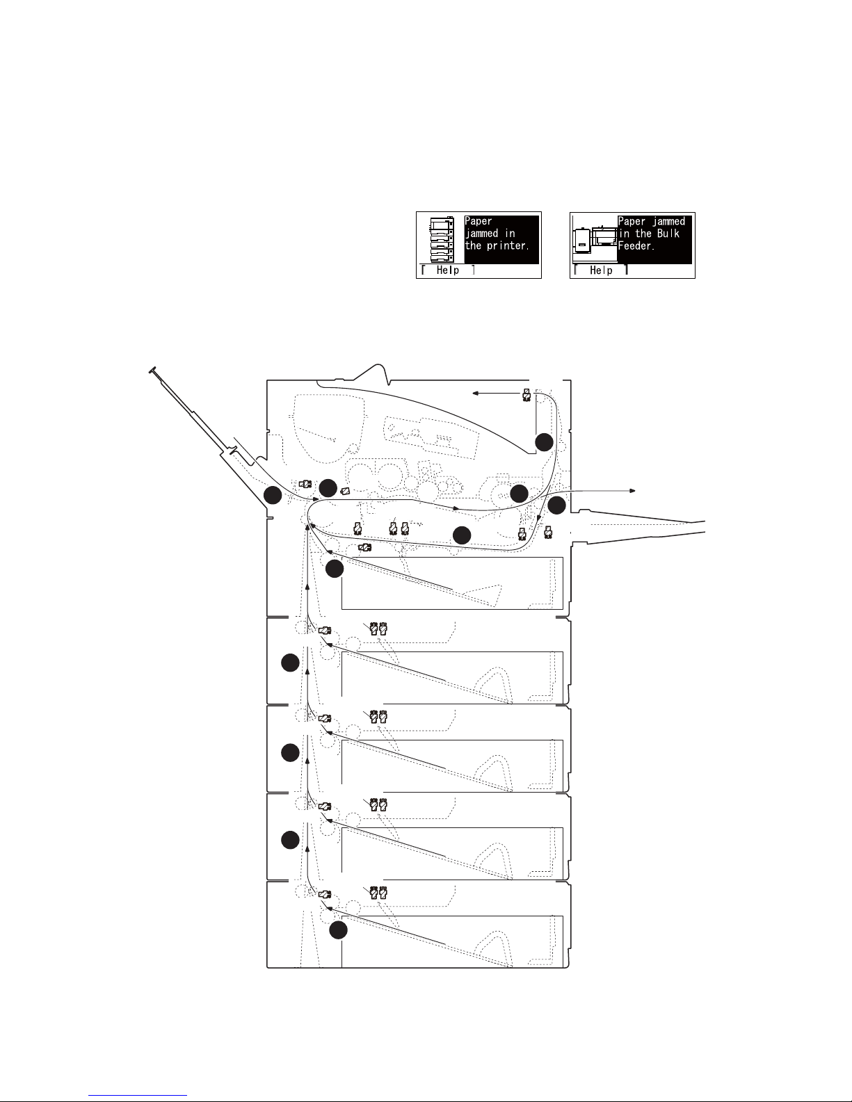
2LV/2L1/2L2/2MS/2MT
EFS
DUS1
ES
DUS2
PS1/PS2
RS1(3)
RS2
MPPS
LS
PFLS1
PFPS1
PFPFS1
PFLS2
PFPS2
PFPFS2
PFLS3
PFPS3
PFPFS3
PFLS4
PFPS4
PFPFS4
I
J
K
L
E
F
G
H
A
B
C
1-4 Troubleshooting
1-4-1 Paper misfeed detection
(1) Paper misfeed indication
When a paper misfeed occurs, the machine immediately stops printing and displays the paper misfeed message on the operation panel. To remove paper misfeed in the machine, pull out the cassette, open the front
cover or the rear cover.
(2) Paper misfeed detection condition
(2-1) PF-320 (500 sheets Paper feeder)
Figure 1-4-1 Paper jam location
1-4-1
Page 62

(2-2) PF-315+ (Bulk Paper Feeder)
(A)Misfeed in cassette1
(B)Misfeed in paper feed section
(C)Misfeed in MP tray
(D)Misfeed in bulk paper feeder (Option)
(E)Misfeed in cassette2 (Option)
(F)Misfeed in cassette3 (Option)
(G)Misfeed in cassette4 (Option)
(H)Misfeed in cassette5 (Option)
(I)Misfeed in exit conveying section
(J)Misfeed in rear cover section
(K)Misfeed in duplex conveying section
(L)Misfeed in fuser section
2LV/2L1/2L2/2MS/2MT
EFS
PFLS5
MPPS
D
PFPFS5
Figure 1-4-2 Paper jam location
RS1(3)
RS2
PS1/PS2
LS
DUS2
ES
DUS1
1-4-2
Page 63

2LV/2L1/2L2/2MS/2MT
Code Contents Conditions
0000 Initial jam The power is turned on when a sensor in the con-
veying system is on.
0100 Secondary paper feed
request time out
0101 Waiting for process package
Secondary paper feed request given by the controller is unreachable.
Process package won’t be ready.
to be ready
0104 Waiting for conveying pack-
Conveying package won’t be ready.
age to be ready
0106 Paper feeding request for
duplex printing time out
0107 Waiting for fuser package to
Paper feeding request for duplex printing given by
the controller is unreachable.
Fuser package won’t be ready.
be ready
0120 Receiving a duplex paper
feeding request while paper
is empty
0121 Exceeding number of duplex
pages circulated
Paper feed request was received from the duplex
section despite the absence of paper in the duplex
section.
The controller issued the duplex section a request
for more pages than the duplex print cycle contains.
0501 No paper feed of jam The registration sensor 2 (RS2) does not turn on
during paper feed from cassette 1.
0502 PF feed sensor 1 (PFPFS1) does not turn on dur-
ing paper feed from cassette 2.
0503 PF feed sensor 2 (PFPFS2) does not turn on dur-
ing paper feed from cassette 3.
0504 PF feed sensor 3 (PFPFS3) does not turn on dur-
ing paper feed from cassette 4.
0505 PF feed sensor 4 (PFPFS4) does not turn on dur-
ing paper feed from cassette 5.
0508 The registration sensor 2 (RS2) does not turn on
during paper feed from duplex section.
0509 The registration sensor 2 (RS2) does not turn on
during paper feed from MP tray.
Jam
location*
-
-
-
-
-
-
-
-
A
E
F
G
H
B
C
*: Refer to figure 1-4-1 for paper jam location (see page 1-4-1).
1-4-3
Page 64

2LV/2L1/2L2/2MS/2MT
Code Contents Conditions
0511 Multiple sheets of jam The registration sensor 2 (RS2) does not turn off
during paper feed from cassette 1.
0512 PF feed sensor 1 (PFPFS1) does not turn off dur-
ing paper feed from cassette 2.
0513 PF feed sensor 2 (PFPFS2) does not turn off dur-
ing paper feed from cassette 3.
0514 PF feed sensor 3 (PFPFS3) does not turn off dur-
ing paper feed from cassette 4.
0515 PF feed sensor 4 (PFPFS4) does not turn off dur-
ing paper feed from cassette 5.
0518 The registration sensor 2 (RS2) does not turn off
during paper feed from duplex section.
0519 The registration sensor 2 (RS2) does not turn off
during paper feed from MP tray.
0529 No paper feed of jam
(Bulk feeder)
0539 Multiple sheets of jam
(Bulk feeder)
1403 PF feed sensor 1 non arrival
jam
The registration sensor 2 (RS2) does not turn on
during paper feed from bulk feeder.
The registration sensor 2 (RS2) does not turn off
during paper feed from bulk feeder.
PF feed sensor 1 (PFPFS1) does not turn on during paper feed from cassette 3.
1404 PF feed sensor 1 (PFPFS1) does not turn on dur-
ing paper feed from cassette 4.
1405 PF feed sensor 1 (PFPFS1) does not turn on dur-
ing paper feed from cassette 5.
Jam
location*
B
B
B
B
B
B
B
D
B
E
E
E
1413 PF feed sensor 1 stay jam PF feed sensor 1 (PFPFS1) does not turn off dur-
ing paper feed from cassette 3.
1414 PF feed sensor 1 (PFPFS1) does not turn off dur-
ing paper feed from cassette 4.
1415 PF feed sensor 1 (PFPFS1) does not turn off dur-
ing paper feed from cassette 5.
1604 PF feed sensor 2 non arrival
jam
PF feed sensor 2 (PFPFS2) does not turn on during paper feed from cassette 4.
1605 PF feed sensor 2 (PFPFS2) does not turn on dur-
ing paper feed from cassette 5.
1614 PF feed sensor 2 stay jam PF feed sensor 2 (PFPFS2) does not turn off dur-
ing paper feed from cassette 4.
1615 PF feed sensor 2 (PFPFS2) does not turn off dur-
ing paper feed from cassette 5.
1805 PF feed sensor 3 non arrival
jam
PF feed sensor 3 (PFPFS3) does not turn on during paper feed from cassette 5.
1815 PF feed sensor 3 stay jam PF feed sensor 3 (PFPFS3) does not turn off dur-
ing paper feed from cassette 5.
*: Refer to figure 1-4-1 for paper jam location (see page 1-4-1).
E
E
E
F
F
F
F
G
G
1-4-4
Page 65

2LV/2L1/2L2/2MS/2MT
Code Contents Conditions
4002 Registration sensor 2 non
arrival jam
The registration sensor 2 (RS2) does not turn on
during paper feed from cassette 2.
4003 The registration sensor 2 (RS2) does not turn on
during paper feed from cassette 3.
4004 The registration sensor 2 (RS2) does not turn on
during paper feed from cassette 4.
4005 The registration sensor 2 (RS2) does not turn on
during paper feed from cassette 5.
4012 Registration sensor 2 stay
jam
The registration sensor 2 (RS2) does not turn off
during paper feed from cassette 2.
4013 The registration sensor 2 (RS2) does not turn off
during paper feed from cassette 3.
4014 The registration sensor 2 (RS2) does not turn off
during paper feed from cassette 4.
4015 The registration sensor 2 (RS2) does not turn off
during paper feed from cassette 5.
4101 Registration sensor 3 non
arrival jam
The registration sensor 3 (RS3) does not turn on
during paper feed from cassette 1.
4102 The registration sensor 3 (RS3) does not turn on
during paper feed from cassette 2.
4103 The registration sensor 3 (RS3) does not turn on
during paper feed from cassette 3.
4104 The registration sensor 3 (RS3) does not turn on
during paper feed from cassette 4.
Jam
location*
B
B
B
B
B
B
B
B
B
B
B
B
4105 The registration sensor 3 (RS3) does not turn on
during paper feed from cassette 5.
4108 The registration sensor 3 (RS3) does not turn on
during paper feed from duplex section.
4109 The registration sensor 3 (RS3) does not turn on
during paper feed from MP tray.
*: Refer to figure 1-4-1 for paper jam location (see page 1-4-1).
B
B
B
1-4-5
Page 66

2LV/2L1/2L2/2MS/2MT
Code Contents Conditions
4111 Registration sensor 3 stay
jam
The registration sensor 3 (RS3) does not turn off
during paper feed from cassette 1.
4112 The registration sensor 3 (RS3) does not turn off
during paper feed from cassette 2.
4113 The registration sensor 3 (RS3) does not turn off
during paper feed from cassette 3.
4114 The registration sensor 3 (RS3) does not turn off
during paper feed from cassette 4.
4115 The registration sensor 3 (RS3) does not turn off
during paper feed from cassette 5.
4118 The registration sensor 3 (RS3) does not turn off
during paper feed from duplex section.
4119 The registration sensor 3 (RS3) does not turn off
during paper feed from MP tray.
4201 Ejetct sensor non arrival jam The eject sensor (ES) does not turn on during
paper feed from cassette 1.
4202 The eject sensor (ES) does not turn on during
paper feed from cassette 2.
4203 The eject sensor (ES) does not turn on during
paper feed from cassette 3.
4204 The eject sensor (ES) does not turn on during
paper feed from cassette 4.
4205 The eject sensor (ES) does not turn on during
paper feed from cassette 5.
Jam
location*
B
B
B
B
B
B
B
I
I
I
I
I
4208 The eject sensor (ES) does not turn on during
paper feed from duplex section.
4209 The eject sensor (ES) does not turn on during
paper feed from MP tray.
*: Refer to figure 1-4-1 for paper jam location (see page 1-4-1).
I
I
1-4-6
Page 67

2LV/2L1/2L2/2MS/2MT
Code Contents Conditions
4211 Ejetct sensor stay jam The eject sensor (ES) does not turn off during
paper feed from cassette 1.
4212 The eject sensor (ES) does not turn off during
paper feed from cassette 2.
4213 The eject sensor (ES) does not turn off during
paper feed from cassette 3.
4214 The eject sensor (ES) does not turn off during
paper feed from cassette 4.
4215 The eject sensor (ES) does not turn off during
paper feed from cassette 5.
4218 The eject sensor (ES) does not turn off during
paper feed from duplex section.
4219 The eject sensor (ES) does not turn off during
paper feed from MP tray.
4301 Duplex sensor 1 non arrival
jam
The duplex sensor 1 (DUS1) does not turn on during paper feed from cassette 1.
4302 The duplex sensor 1 (DUS1) does not turn on dur-
ing paper feed from cassette 2.
4303 The duplex sensor 1 (DUS1) does not turn on dur-
ing paper feed from cassette 3.
4304 The duplex sensor 1 (DUS1) does not turn on dur-
ing paper feed from cassette 4.
4305 The duplex sensor 1 (DUS1) does not turn on dur-
ing paper feed from cassette 5.
Jam
location*
I or L
I or L
I or L
I or L
I or L
I or L
I or L
J
J
J
J
J
4309 The duplex sensor 1 (DUS1) does not turn on dur-
ing paper feed from MP tray or bulk feeder.
4401 Duplex sensor 2 non arrival
jam
The duplex sensor 2 (DUS2) does not turn on during paper feed from cassette 1.
4402 The duplex sensor 2 (DUS2) does not turn on dur-
ing paper feed from cassette 2.
4403 The duplex sensor 2 (DUS2) does not turn on dur-
ing paper feed from cassette 3.
4404 The duplex sensor 2 (DUS2) does not turn on dur-
ing paper feed from cassette 4.
4405 The duplex sensor 2 (DUS2) does not turn on dur-
ing paper feed from cassette 5.
4409 The duplex sensor 2 (DUS2) does not turn on dur-
ing paper feed from MP tray or bulk feeder.
4418 Duplex sensor 2 stay jam The duplex sensor 2 (DUS2) does not turn off dur-
ing paper feed from duplex section.
*: Refer to figure 1-4-1 for paper jam location (see page 1-4-1).
J
K
K
K
K
K
K
K
1-4-7
Page 68

2LV/2L1/2L2/2MS/2MT
1-4-2 Self-diagnostic function
(1) Self-diagnostic function
This machine is equipped with self-diagnostic function. When a problem is detected, the machine stops printing and display an error message on the operation panel. An error message consists of a message prompting
a contact to service personnel and a four-digit error code indicating the type of the error.
Total printing
number
Errer code
(2) Self diagnostic codes
If the part causing the problem was not supplied, use the unit including the part for replacement.
Code Contents Causes
0100 Backup memory device
error
0120 MAC address data error
For data in which the MAC
address is invalid.
0130 Backup memory read/write
error (main PWB)
0140 Backup memory data error
(main PWB)
0150 Backup memory read/write
error (engine PWB)
Detecting engine PWB
EEPROM communication
error.
0160 Backup memory data error
(engine PWB)
Defective flash
memory.
Defective main
PWB.
Defective flash
memory.
Defective main
PWB.
Defective flash
memory.
Defective main
PWB.
Defective flash
memory.
Defective main
PWB.
Improper installation engine PWB
EEPROM.
Defective engine
PWB.
Device damage of
EEPROM.
Defective
EEPROM.
Defective engine
PWB.
Check procedures/
corrective measures
Replace the main PWB and check for correct operation (see page 1-5-22).
Replace the main PWB and check for correct operation (see page 1-5-22).
Replace the main PWB and check for correct operation (see page 1-5-22).
Replace the main PWB and check for correct operation (see page 1-5-22).
Replace the main PWB and check for correct operation (see page 1-5-22).
Check the installation of the EEPROM and
remedy if necessary.
Replace the engine PWB and check for correct operation (see page 1-5-22).
Contact the Service Administrative Division.
Replace the engine PWB and check for correct operation (see page 1-5-22).
1-4-8
Page 69

2LV/2L1/2L2/2MS/2MT
Code Contents Causes
0170 Billing counting error
Data damage of
EEPROM.
A checksum error is detected
in the main and engine
Defective PWB. Replace the main PWB or the engine PWB
backup memories for the billing counters.
0190 Backup memory device
error (engine PWB)
0800 Image processing error
Defective engine
PWB.
Defective main
PWB.
JAM010x is detected twice.
0840 Faults of RTC
The battery is dis-
connected from the
The time is judged to go back
based on the comparison of
the RTC time and the current
time or five years or more
main PWB.
Defective main
PWB.
have passed.
Check procedures/
corrective measures
Contact the Service Administrative Division.
and check for correct operation (see page 15-22, 1-5-22).
Replace the engine PWB and check for correct operation (see page 1-5-22).
Replace the main PWB and check for correct operations page 1-5-22).
Check visually and remedy if necessary
Replace the main PWB and check for correct operation (see page 1-5-22).
1010 Lift motor error
(60/50/45 ppm model only)
After cassette 1 is inserted, lift
sensor does not turn on within
10 s. This error is detected
four times successively.
Defective bottom
plate elevation
mechanism in the
Check to see if the bottom plate can move
smoothly and repair it if any problem is
found.
cassette.
Defective connec-
tor cable or poor
contact in the con-
Reinsert the connector. Also check for continuity within the connector cable. If none,
replace the cable.
nector.
Lift motor and engine PWB (YC13)
Defective drive
transmission sys-
tem of the lift
Check if the gears rotate smoothly. If not,
grease the bushes and gears. Check for
broken gears and replace if any.
motor.
Defective lift motor. Replace the lift motor.
Defective engine
PWB.
Replace the engine PWB and check for correct operation (see page 1-5-22).
1-4-9
Page 70

2LV/2L1/2L2/2MS/2MT
Code Contents Causes
1020 PF lift motor 1 error
(paper feeder)
Defective bottom
plate elevation
mechanism in the
After cassette 2 is inserted,
PF lift sensor 1 does not turn
on. This error is detected four
times successively.
cassette.
Defective connec-
tor cable or poor
contact in the con-
nector.
Defective drive
transmission sys-
tem of the PF lift
motor.
Defective PF lift
motor.
Defective PF main
PWB.
Check procedures/
corrective measures
Check to see if the bottom plate can move
smoothly and repair it if any problem is
found.
Reinsert the connector. Also check for continuity within the connector cable. If none,
replace the cable.
PF lift motor 1 and PF main PWB (YC7)
Check if the gears rotate smoothly. If not,
grease the bushes and gears. Check for
broken gears and replace if any.
Replace the PF lift motor 1.
Replace the PF main PWB (Refer to the service manual for the paper feeder).
1030 PF lift motor 2 error
(paper feeder)
After cassette 3 is inserted,
PF lift sensor 2 does not turn
on. This error is detected four
times successively.
Defective bottom
plate elevation
mechanism in the
cassette.
Defective connec-
tor cable or poor
contact in the con-
nector.
Defective drive
transmission sys-
tem of the PF lift
motor.
Defective PF lift
motor.
Defective PF main
PWB.
Check to see if the bottom plate can move
smoothly and repair it if any problem is
found.
Reinsert the connector. Also check for continuity within the connector cable. If none,
replace the cable.
PF lift motor 2 and PF main PWB (YC7)
Check if the gears rotate smoothly. If not,
grease the bushes and gears. Check for
broken gears and replace if any.
Replace the PF lift motor 2.
Replace the PF main PWB (Refer to the service manual for the paper feeder).
1-4-10
Page 71

2LV/2L1/2L2/2MS/2MT
Code Contents Causes
1040 PF lift motor 3 error
(paper feeder)
Defective bottom
plate elevation
mechanism in the
After cassette 4 is inserted,
PF lift sensor 3 does not turn
on. This error is detected four
times successively.
cassette.
Defective connec-
tor cable or poor
contact in the con-
nector.
Defective drive
transmission sys-
tem of the PF lift
motor.
Defective PF lift
motor.
Defective PF main
PWB.
1050 PF lift motor 4 error
(paper feeder)
Defective bottom
plate elevation
mechanism in the
After cassette 5 is inserted,
PF lift sensor 4 does not turn
on. This error is detected four
times successively.
cassette.
Defective connec-
tor cable or poor
contact in the con-
nector.
Defective drive
transmission sys-
tem of the PF lift
motor.
Defective PF lift
motor.
Defective PF main
PWB.
1140 BPF lift motor upward error
(Bulk paper feeder)
Defective connec-
tor cable or poor
contact in the conBPF lift maximum sensor
does not turn on.
The lock signal of the motor is
detected continuously three
times.
nector.
Defective drive
transmission sys-
tem of the motor.
Defective BPF lift
motor.
Defective BPF
main PWB.
Check procedures/
corrective measures
Check to see if the bottom plate can move
smoothly and repair it if any problem is
found.
Reinsert the connector. Also check for continuity within the connector cable. If none,
replace the cable.
PF lift motor 3 and PF main PWB (YC7)
Check if the gears rotate smoothly. If not,
grease the bushes and gears. Check for
broken gears and replace if any.
Replace the PF lift motor 3.
Replace the PF main PWB (Refer to the service manual for the paper feeder).
Check to see if the bottom plate can move
smoothly and repair it if any problem is
found.
Reinsert the connector. Also check for continuity within the connector cable. If none,
replace the cable.
PF lift motor 4 and PF main PWB (YC7)
Check if the gears rotate smoothly. If not,
grease the bushes and gears. Check for
broken gears and replace if any.
Replace the PF lift motor 4.
Replace the PF main PWB (Refer to the service manual for the paper feeder).
Reinsert the connector. Also check for continuity within the connector cable. If none,
replace the cable.
BPF lift motor and BPF main PWB
Check if the gears rotate smoothly. If not,
grease the bushes and gears. Check for
broken gears and replace if any.
Replace the BPF lift motor.
Replace the BPF main PWB (Refer to the
service manual for the paper feeder).
1-4-11
Page 72

2LV/2L1/2L2/2MS/2MT
Code Contents Causes
1150 BPF lift motor downward
error (Bulk paper feeder)
Defective connec-
tor cable or poor
contact in the conBPF lift minimum sensor does
not turn on.
The lock signal of the motor is
detected continuously three
times.
nector.
Defective drive
transmission sys-
tem of the motor.
Defective BPF lift
motor.
Defective BPF
main PWB.
1800 Paper feeder 1 communica-
tion error
A communication error is
detected 10 times in succession.
Improper installa-
tion paper feeder.
Defective connec-
tor cable or poor
contact in the con-
nector.
Defective engine
PWB.
Defective PF main
PWB.
Check procedures/
corrective measures
Reinsert the connector. Also check for continuity within the connector cable. If none,
replace the cable.
BPF lift motor and BPF main PWB
Check if the gears rotate smoothly. If not,
grease the bushes and gears. Check for
broken gears and replace if any.
Replace the BPF lift motor.
Replace the BPF main PWB (Refer to the
service manual for the paper feeder).
Follow installation instruction carefully again.
Reinsert the connector. Also check for continuity within the connector cable. If none,
replace the cable.
PF main PWB (YC3) and engine PWB
(YC22)
Replace the engine PWB and check for correct operation (see page 1-5-22).
Replace the PF main PWB (Refer to the service manual for the paper feeder).
1810 Paper feeder 2 communica-
tion error
A communication error is
detected 10 times in succession.
1820 Paper feeder 3 communica-
tion error
A communication error is
detected 10 times in succession.
Improper installa-
tion paper feeder.
Defective connec-
tor cable or poor
contact in the con-
nector.
Defective PF main
PWB.
Improper installa-
tion paper feeder.
Defective connec-
tor cable or poor
contact in the con-
nector.
Defective PF main
PWB.
Follow installation instruction carefully again.
Reinsert the connector. Also check for continuity within the connector cable. If none,
replace the cable.
PF main PWB (YC3) and PF main PWB
(YC4)
Replace the PF main PWB (Refer to the service manual for the paper feeder).
Follow installation instruction carefully again.
Reinsert the connector. Also check for continuity within the connector cable. If none,
replace the cable.
PF main PWB (YC3) and PF main PWB
(YC4)
Replace the PF main PWB (Refer to the service manual for the paper feeder).
1-4-12
Page 73

2LV/2L1/2L2/2MS/2MT
Code Contents Causes
1830 Paper feeder 4 communica-
tion error
A communication error is
detected 10 times in succession.
Improper installa-
tion paper feeder.
Defective connec-
tor cable or poor
contact in the con-
nector.
Defective PF main
PWB.
1900 Paper feeder 1/BPF paper
feeder EEPROM error
When writing the data, the
write data and the read data is
Defective PF main
PWB.
Device damage of
EEPROM.
not in agreement.
1910 Paper feeder 2 EEPROM
error
When writing the data, the
write data and the read data is
Defective PF main
PWB.
Device damage of
EEPROM.
not in agreement.
1920 Paper feeder 3 EEPROM
error
When writing the data, the
write data and the read data is
Defective PF main
PWB.
Device damage of
EEPROM.
not in agreement.
Check procedures/
corrective measures
Follow installation instruction carefully again.
Reinsert the connector. Also check for continuity within the connector cable. If none,
replace the cable.
PF main PWB (YC3) and PF main PWB
(YC4)
Replace the PF main PWB (Refer to the service manual for the paper feeder).
Replace the PF main PWB or the BPF main
PWB (Refer to the service manual for the
paper feeder).
Replace the PF main PWB (Refer to the service manual for the paper feeder).
Replace the PF main PWB (Refer to the service manual for the paper feeder).
1930 Paper feeder 4 EEPROM
error
When writing the data, the
write data and the read data is
not in agreement.
2000 Main motor drive error
The main motor is not stabilized within 2 s after driving
starts.
Defective PF main
PWB.
Device damage of
EEPROM.
Defective connec-
tor cable or poor
contact in the con-
nector.
Defective drive
transmission sys-
tem of the main
motor.
Defective main
motor.
Defective engine
PWB.
1-4-13
Replace the PF main PWB (Refer to the service manual for the paper feeder).
Reinsert the connector. Also check for continuity within the connector cable. If none,
replace the cable.
Main motor and engine PWB (YC4)
Check if the rollers and gears rotate
smoothly. If not, grease the bushes and
gears. Check for broken gears and replace if
any.
Replace the main motor.
Replace the engine PWB and check for correct operation (see page 1-5-22).
Page 74

2LV/2L1/2L2/2MS/2MT
Code Contents Causes
2010 Main motor steady-state
error
Defective connec-
tor cable or poor
contact in the conStable OFF is detected for 2 s
continuously after main motor
stabilized.
nector.
Defective drive
transmission sys-
tem of the main
motor.
Defective main
motor.
Defective engine
PWB.
2200 Drum motor drive error
(60/50/45 ppm model only)
Defective connec-
tor cable or poor
contact in the conThe drum motor is not stabilized within 2 s after driving
starts.
nector.
Defective drive
transmission sys-
tem of the drum
motor.
Defective drum
motor.
Defective engine
PWB.
Check procedures/
corrective measures
Reinsert the connector. Also check for continuity within the connector cable. If none,
replace the cable.
Main motor and engine PWB (YC4)
Check if the rollers and gears rotate
smoothly. If not, grease the bushes and
gears. Check for broken gears and replace if
any.
Replace the main motor.
Replace the engine PWB and check for correct operation (see page 1-5-22).
Reinsert the connector. Also check for continuity within the connector cable. If none,
replace the cable.
Drum motor and engine PWB (YC4)
Check if the rollers and gears rotate
smoothly. If not, grease the bushes and
gears. Check for broken gears and replace if
any.
Replace the drum motor.
Replace the engine PWB and check for correct operation (see page 1-5-22).
2210 Drum motor steady-state
error
(60/50/45 ppm model only)
Stable OFF is detected for 2 s
continuously after drum motor
stabilized.
Defective connec-
tor cable or poor
contact in the con-
nector.
Defective drive
transmission sys-
tem of the drum
motor.
Defective drum
motor.
Defective engine
PWB.
1-4-14
Reinsert the connector. Also check for continuity within the connector cable. If none,
replace the cable.
Drum motor and engine PWB (YC4)
Check if the rollers and gears rotate
smoothly. If not, grease the bushes and
gears. Check for broken gears and replace if
any.
Replace the drum motor.
Replace the engine PWB and check for correct operation (see page 1-5-22).
Page 75

2LV/2L1/2L2/2MS/2MT
Code Contents Causes
2330 Fuser pressure release
motor error
(Over-current)
(60/50/45 ppm model only)
Defective connec-
tor cable or poor
contact in the con-
nector.
The over-current detection
signal of the motor is detected
continuously twenty times.
Defective drive
transmission sys-
tem of the fuser
pressure release
motor.
Defective fuser
pressure release
motor.
Defective PWB. Replace the relay-L PWB or engine PWB.
2340 Fuser pressure release
motor error
(Timeout)
(60/50/45 ppm model only)
Defective connec-
tor cable or poor
contact in the con-
nector.
The position detection sensor
is not detected continuously
for 30 s.
Defective drive
transmission sys-
tem of the fuser
pressure release
motor.
Check procedures/
corrective measures
Reinsert the connector. Also check for continuity within the connector cable. If none,
replace the cable.
Fuser pressure release motor and relay-L
PWB(YC11)
Relay-L PWB and engine PWB(YC2)
Check if the gears rotate smoothly. If not,
grease the bushes and gears. Check for
broken gears and replace if any.
Replace the fuser pressure release motor.
(See Page 1-5-24,1-5-22)
Reinsert the connector. Also check for continuity within the connector cable. If none,
replace the cable.
Fuser pressure release motor and relay-L
PWB(YC11)
Relay-L PWB and engine PWB(YC2)
Check if the gears rotate smoothly. If not,
grease the bushes and gears. Check for
broken gears and replace if any.
2600 PF drive motor 1 error
(paper feeder 1)
When the PF drive motor is
driven, error signal is detected
continuously for 2 s.
Defective fuser
Replace the fuser pressure release motor.
pressure release
motor.
Defective PWB. Replace the relay-L PWB or engine PWB.
(See Page 1-5-24,1-5-22)
Defective connector cable or poor
contact in the connector.
Defective drive
transmission system of the PF drive
motor.
Defective PF drive
Reinsert the connector. Also check for conti-
nuity within the connector cable. If none,
replace the cable.
PF drive motor 1 and PF main PWB (YC6)
Check if the rollers and gears rotate
smoothly. If not, grease the bushes and
gears. Check for broken gears and replace if
any.
Replace the PF drive motor 1.
motor.
Defective PF main
PWB.
Replace the PF main PWB (Refer to the ser-
vice manual for the paper feeder).
1-4-15
Page 76

2LV/2L1/2L2/2MS/2MT
Code Contents Causes
2610 PF drive motor 2 error
(paper feeder 2)
Defective connector cable or poor
contact in the con-
When the PF drive motor is
driven, error signal is detected
continuously for 2 s.
nector.
Defective drive
transmission system of the PF drive
motor.
Defective PF drive
motor.
Defective PF main
PWB.
2620 PF drive motor 3 error
(paper feeder 3)
Defective connector cable or poor
contact in the con-
When the PF drive motor is
driven, error signal is detected
continuously for 2 s.
nector.
Defective drive
transmission system of the PF drive
motor.
Defective PF drive
motor.
Defective PF main
PWB.
2630 PF drive motor 4 error
(paper feeder 4)
Defective connector cable or poor
contact in the con-
When the PF drive motor is
driven, error signal is detected
continuously for 2 s.
nector.
Defective drive
transmission system of the PF drive
motor.
Defective PF drive
motor.
Defective PF main
PWB.
4000 Polygon motor synchroni-
zation error
Defective connector cable or poor
contact in the con-
The polygon motor is not stabilized within 20 s after driving
starts.
nector.
Defective polygon
motor.
Defective engine
PWB.
Check procedures/
corrective measures
Reinsert the connector. Also check for conti-
nuity within the connector cable. If none,
replace the cable.
PF drive motor 2 and PF main PWB (YC6)
Check if the rollers and gears rotate
smoothly. If not, grease the bushes and
gears. Check for broken gears and replace if
any.
Replace the PF drive motor 2.
Replace the PF main PWB (Refer to the ser-
vice manual for the paper feeder).
Reinsert the connector. Also check for conti-
nuity within the connector cable. If none,
replace the cable.
PF drive motor 3 and PF main PWB (YC6)
Check if the rollers and gears rotate
smoothly. If not, grease the bushes and
gears. Check for broken gears and replace if
any.
Replace the PF drive motor 3.
Replace the PF main PWB (Refer to the ser-
vice manual for the paper feeder).
Reinsert the connector. Also check for conti-
nuity within the connector cable. If none,
replace the cable.
PF drive motor 4 and PF main PWB (YC6)
Check if the rollers and gears rotate
smoothly. If not, grease the bushes and
gears. Check for broken gears and replace if
any.
Replace the PF drive motor 4.
Replace the PF main PWB (Refer to the ser-
vice manual for the paper feeder).
Reinsert the connector. Also check for conti-
nuity within the connector cable. If none,
replace the cable.
Polygon motor and engine PWB (YC15)
Replace the laser scanner unit (see page 1-
5-18).
Replace the engine PWB and check for cor-
rect operation (see page 1-5-22).
1-4-16
Page 77

2LV/2L1/2L2/2MS/2MT
Code Contents Causes
4200 BD steady-state error
Defective connector cable or poor
When the value of Register
BDSET is 1 after setting Register BDSET as one and passing by BD1 cycle.
contact in the connector.
Defective PD
PWB.
Defective engine
PWB.
5100 Chager current error
Defective connector cable or poor
When the current value measured at the time of potential
contact in the connector.
adjustment is less than 20 μA.
When the current values in
the chager voltage 500V constitute not less than 85% of
target current values.
Defective high
voltage PWB.
Defective engine
PWB.
Check procedures/
corrective measures
Reinsert the connector. Also check for conti-
nuity within the connector cable. If none,
replace the cable.
PD PWB and engine PWB (YC16)
Replace the laser scanner unit (see page 1-
5-18).
Replace the engine PWB and check for cor-
rect operation (see page 1-5-22).
Reinsert the connector. Also check for conti-
nuity within the connector cable. If none,
replace the cable.
Chager unit and high voltage PWB
High voltage PWB and engine PWB (YC16)
Replace the high voltage PWB and check
for correct operation (see page 1-5-26).
Replace the engine PWB and check for cor-
rect operation (see page 1-5-22).
6000 Broken fuser heater wire
(60/50/45 ppm model)
The detection temperature of
fuser thermistor 2 is 100 °C/
212°F or less after the fuser
heater lamp has been turned
on continuously for 30 s.
(40 ppm model)
The detection temperature of
fuser thermistor 1 is 100 °C/
212°F or less after the fuser
heater lamp has been turned
on continuously for 30 s.
Defective connector cable or poor
contact in the connector.
Reinsert the connector. Also check for conti-
nuity within the connector cable. If none,
replace the cable.
Fuser heater and power source PWB (YC2)
Fuser thermistor and Fuser thermistor con-
nect PWB
Fuser thermistor connect PWB and engine
PWB (YC21)
Deformed connec-
See page 1-4-19.
tor pin.
Defective triac. See page 1-4-19.
Fuser thermostat
Reinsert the fuser unit (see page 1-5-19).
triggered.
Broken fuser
heater wire.
Defective engine
PWB.
Replace the engine PWB and check for cor-
rect operation (see page 1-5-22).
1-4-17
Page 78

2LV/2L1/2L2/2MS/2MT
Code Contents Causes
6020 Abnormally high fuser
thermistor 2 temperature
(60/50/45 ppm model only)
The detection temperature of
fuser thermistor 2 is higher
than 235°C/455°F.
In a heater-off state, the
Deformed connector pin.
Defective triac. See page 1-4-19.
Shorted fuser
thermistor.
Defective engine
PWB.
detection temperature of fuser
thermistor 2 is higher than
195°C/383°F after the detection temperature of fuser
thermistor 2 was 155°C/311°F
or less.
6030 Broken fuser thermistor 2
wire
(60/50/45 ppm model only)
Defective connector cable or poor
contact in the connector.
A/D value of the fuser thermistor 2 exceeds 1019 bit continuously for 4 s during warming
up.
Deformed connector pin.
Defective triac. See page 1-4-19.
Check procedures/
corrective measures
See page 1-4-19.
Replace the fuser unit (see page 1-5-19).
Replace the engine PWB and check for cor-
rect operation (see page 1-5-22).
Reinsert the connector. Also check for conti-
nuity within the connector cable. If none,
replace the cable.
Fuser thermistor and fuser thermistor con-
nect PWB
Fuser thermistor connect PWB and engine
PWB (YC21)
See page 1-4-19.
Defective fuser
thermistor.
Defective engine
PWB.
1-4-18
Replace the fuser unit (see page 1-5-19).
Replace the engine PWB and check for cor-
rect operation (see page 1-5-22).
Page 79

2LV/2L1/2L2/2MS/2MT
Code Contents Causes
6000/
6020/
6030/
6120/
6130/
Combined
Broken fuser heater wire
Abnormally high fuser
thermistor 2 temperature
Broken fuser thermistor 2
wire
Abnormally high fuser
thermistor 1 temperature
Broken fuser thermistor 1
wire
Deformed connector pin.
Defective triac. Remove the power cord and check that the
Check procedures/
corrective measures
If the I/F connector pins of the fuser unit and
the main unit are deformed owing to foreign
matters, replace the connectors or the units
including the connectors.
resistance between terminals T1 and T2 of
the triac TRA41 is of several Mega-Ohms
and not shorted (see figure 1-4-3). If failed,
replace the power source PWB (see page 1-
5-25).
T1
T2
TRA41
Power source PWB
Figure 1-4-3
1-4-19
Page 80

2LV/2L1/2L2/2MS/2MT
Code Contents Causes
6120 Abnormally high fuser
thermistor 1 temperature
(60/50/45 ppm model)
The detection temperature of
fuser thermistor 1 is higher
than 245°C/473°F.
In a heater-off state, the
Deformed connector pin.
Defective triac. See page 1-4-19.
Shorted fuser
thermistor.
Defective engine
PWB.
detection temperature of fuser
thermistor 1 is higher than
195°C/383°F after the detection temperature of fuser
thermistor 1 was 155°C/311°F
or less.
(40 ppm model)
The detection temperature of
fuser thermistor 1 is higher
than 250°C/482°F.
In a heater-off state, the
detection temperature of fuser
thermistor 1 is higher than
170°C/338°F after the detection temperature of fuser
thermistor 1 was 155°C/311°F
or less.
Check procedures/
corrective measures
See page 1-4-19.
Replace the fuser unit (see page 1-5-19).
Replace the engine PWB and check for cor-
rect operation (see page 1-5-22).
6130 Broken fuser thermistor 1
wire
A/D value of the fuser thermistor 1 exceeds 1019 bit continuously for 4 s during warming
up.
Defective connector cable or poor
contact in the connector.
Reinsert the connector. Also check for conti-
nuity within the connector cable. If none,
replace the cable.
Fuser thermistor and fuser thermistor con-
nect PWB
Fuser thermistor connect PWB and engine
PWB (YC21)
Deformed connec-
See page 1-4-19.
tor pin.
Defective triac. See page 1-4-19.
Defective fuser
Replace the fuser unit (see page 1-5-19).
thermistor.
Defective engine
PWB.
Replace the engine PWB and check for cor-
rect operation (see page 1-5-22).
1-4-20
Page 81

2LV/2L1/2L2/2MS/2MT
Code Contents Causes
6400 Zero-cross signal error
Defective connector cable or poor
While fuser heater control is
performed, the zero-cross sig-
contact in the connector.
nal is not input within 2 s.
Defective power
source PWB or
engine PWB.
7000 Toner motor error
Defective connector cable or poor
During driving the toner motor,
an over-current detection sig-
contact in the connector.
nal is detected at intervals of
10 ms as for 300 accumulation.
Defective toner
motor.
Defective engine
PWB.
7100 Toner sensor error
Defective connector cable or poor
Sensor output value of 930 or
more continuously for 5 s.
contact in the connector.
Defective toner
sensor.
Defective engine
PWB.
Check procedures/
corrective measures
Reinsert the connector. Also check for conti-
nuity within the connector cable. If none,
replace the cable.
Power source PWB (YC3) and engine PWB
(YC1)
Replace the power source PWB or the
engine PWB and check for correct operation
(see page 1-5-22).
Reinsert the connector. Also check for conti-
nuity within the connector cable. If none,
replace the cable.
Toner motor and drum PWB (YC4)
Drum PWB and relay-L PWB (YC3)
Relay-L PWB and engine PWB (YC2)
Replace the toner motor.
Replace the engine PWB and check for cor-
rect operation (see page 1-5-22).
Reinsert the connector. Also check for conti-
nuity within the connector cable. If none,
replace the cable.
Toner sensor and drum PWB (YC3)
Drum PWB and relay-L PWB (YC3)
Relay-L PWB and engine PWB (YC2)
Replace the developer unit.
(See Page 1-5-13)
Replace the engine PWB and check for cor-
rect operation (see page 1-5-22).
7400 Developer unit non-install-
ing error
Sensor output value of 31 or
less continuously for 5 s.
Defective connector cable or poor
contact in the connector.
Defective toner
sensor.
Defective engine
PWB.
1-4-21
Reinsert the connector. Also check for conti-
nuity within the connector cable. If none,
replace the cable.
Developer unit and drum PWB (YC3)
Drum PWB and relay-L PWB (YC3)
Relay-L PWB and engine PWB (YC2)
Replace the developer unit.
(See Page 1-5-13)
Replace the engine PWB and check for cor-
rect operation (see page 1-5-22).
Page 82

2LV/2L1/2L2/2MS/2MT
Code Contents Causes
7410 Drum unit type mismatch
error
Defective connector cable or poor
contact in the con-
The drum PWB EEPROM
nector.
does not communicate
normally.
Absence of the drum unit
is detected.
Defective toner
sensor.
Defective engine
PWB.
7800 Broken external thermistor
wire
Defective connector cable or poor
contact in the con-
The average of thermistor output value of 1016 or more
continuously for 160 ms.
The average of thermistor out-
nector.
Defective temperature sensor.
put value of 930 or more continuously for 5 s.
Check procedures/
corrective measures
Reinsert the connector. Also check for conti-
nuity within the connector cable. If none,
replace the cable.
Drum unit and drum connect PWB (YC1)
Drum connect PWB and relay-L PWB (YC3)
Relay-L PWB and engine PWB (YC2)
Replace the drum unit.
(See Page 1-5-13)
Replace the engine PWB and check for cor-
rect operation (see page 1-5-22).
Reinsert the connector. Also check for conti-
nuity within the connector cable. If none,
replace the cable.
Operation PWB and engine PWB (YC17)
Replace the operation PWB.
7810 Short-circuited external
thermistor wire
The average of thermistor output value of 31 or less continuously for 5 s.
7900 Drum unit EEPROM error
No response is issued from
the device in reading/writing
for 5 ms or more and this
problem is repeated five times
successively.
Mismatch of reading data from
two locations occurs eight
times successively.
Mismatch between writing
data and reading data occurs
eight times successively.
Defective connector cable or poor
contact in the connector.
Defective temperature sensor.
Defective connector cable or poor
contact in the connector.
Defective drum
unit.
Reinsert the connector. Also check for conti-
nuity within the connector cable. If none,
replace the cable.
Operation PWB and engine PWB (YC17)
Replace the operation PWB.
Reinsert the connector. Also check for conti-
nuity within the connector cable. If none,
replace the cable.
Drum unit and drum connect PWB (YC1)
Drum connect PWB and relay-L PWB (YC3)
Relay-L PWB and engine PWB (YC15)
Replace the drum unit (see 1-5-15).
1-4-22
Page 83

2LV/2L1/2L2/2MS/2MT
Code Contents Causes
F000 Main PWB - operation PWB
communication error
Defective connector cable or poor
contact in the connector.
Defective main
PWB.
Defective operation PWB.
F010 Main PWB checksum error Defective main
PWB.
F020 Main PWB RAM checksum
error
Defective main
memory (RAM) in
main PWB
Defective
expended memory
(DIMM)
Check procedures/
corrective measures
Reinsert the connector. Also check for conti-
nuity within the connector cable. If none,
replace the cable.
Operation PWB and engine PWB (YC17)
Turn the main power switch off/on to restart
the machine. If the error is not resolved,
replace main PWB (see page 1-5-22).
Replace the operation PWB and check for
correct operation.
Turn the main power switch off/on to restart
the machine. If the error is not resolved,
replace main PWB (see page 1-5-22).
Turn the main power switch off/on to restart
the machine. If the error is not resolved,
replace main PWB (see page 1-5-22).
Replace the expansion memory (DIMM).
(See Page 1-2-12)
Also in the case of the capacity besides
specification, it displays.
F040 Main PWB - print engine
communication error
F050 Print engine ROM check-
sum error
Defective main
PWB.
Defective engine
PWB.
Defective engine
PWB.
Turn the main power switch off/on to restart
the machine. If the error is not resolved,
replace main PWB (see page 1-5-22).
Replace the engine PWB and check for cor-
rect operation (see page 1-5-22).
Turn the main power switch off/on to restart
the machine. If the error is not resolved,
replace engine PWB (see page 1-5-22).
1-4-23
Page 84

2LV/2L1/2L2/2MS/2MT
1-4-3 Image formation problems
If the part causing the problem was not supplied, use the unit including the part for replacement.
(1) No image
appears (entirely
white).
See page 1-4-25 See page 1-4-25 See page 1-4-26 See page 1-4-27 See page 1-4-27
(6) Black streaks
are printed vertically.
See page 1-4-28 See page 1-4-28 See page 1-4-28 See page 1-4-29 See page 1-4-29
(11) Offset occurs. (12) Part of image is
(2) No image
appears (entirely
black).
(7) Streaks are
printed horizontally.
missing.
(3) Image is too
light.
(8) Spots are
printed.
(13)Fusing is loose. (14)Image is out of
(4) The back-
ground is colored.
(9) Image is
blurred.
focus.
(5) White streaks
are printed vertically.
(10)Paper is wrin-
kled.
See page 1-4-29 See page 1-4-29 See page 1-4-30 See page 1-4-30
1-4-24
Page 85

2LV/2L1/2L2/2MS/2MT
(1) No image appears (entirely white).
Print example Causes Check procedures/corrective measures
Defective
developer
bias output.
No LSU
laser is output.
Defective connector cable
or poor contact in the connector.
Defective high voltage
PWB.
Defective engine PWB. Replace the engine PWB (see page 1-5-22).
Defective connector cable
or poor contact in the connector.
The shutter of a laser scanner unit does not open.
Defective laser scanner
unit.
Defective engine PWB. Replace the engine PWB (see page 1-5-22).
Defective main PWB. Replace the main PWB (see page 1-5-22).
Reinsert the connector. Also check for continuity within the connector cable. If none,
replace the cable.
Developer unit and high voltage PWB
High voltage PWB and engine PWB (YC19)
Replace the high voltage PWB
(see page 1-5-26).
Reinsert the connector. Also check for continuity within the connector cable. If none,
replace the cable.
Laser scanner unit and engine PWB (YC16)
The operating state of a link part with an top
cover is checked.
Replace the laser scanner unit
(see page 1-5-18).
(2) No image appears (entirely black).
Print example Causes Check procedures/corrective measures
No main
charging.
Defective connector cable
or poor contact in the connector.
Defective poor connection
of the charger roller
Defective charger roller unit. Replace the charger roller unit
Defective high voltage
PWB.
Defective engine PWB. Replace the engine PWB (see page 1-5-22).
Reinsert the connector. Also check for continuity within the connector cable. If none,
replace the cable.
Chager roller unit and high voltage PWB
High voltage PWB and engine PWB (YC19)
Connection is checked by the electrical connection inspection of the charger roller.
(see page 1-5-15).
Replace the high voltage PWB
(see page 1-5-26).
1-4-25
Page 86

2LV/2L1/2L2/2MS/2MT
(3) Image is too light.
Print example Causes Check procedures/corrective measures
Dew condensation of the drum surface. Perform the drum surface refreshing in a sys-
tem menu.
The paper is moist. The storage state of a paper is checked.
Defective
transfer
charger output.
Defective
developer
bias output.
Insufficient toner. If the display shows the message requesting
Defective connector cable
or poor contact in the connector.
Defective high voltage
PWB.
Defective engine PWB. Replace the engine PWB (see page 1-5-22).
Defective connector cable
or poor contact in the connector.
Defective high voltage
PWB.
Defective engine PWB. Replace the engine PWB (see page 1-5-22).
Reinsert the connector. Also check for continuity within the connector cable. If none,
replace the cable.
Transfer roller unit and high voltage PWB
High voltage PWB and engine PWB (YC19)
Replace the high voltage PWB
(see page 1-5-26).
Reinsert the connector. Also check for continuity within the connector cable. If none,
replace the cable.
Developer unit and high voltage PWB
High voltage PWB and engine PWB (YC10)
Replace the high voltage PWB
(see page 1-5-26).
toner replenishment, replace the container.
1-4-26
Page 87

2LV/2L1/2L2/2MS/2MT
(4) The background is colored.
Print example Causes Check procedures/corrective measures
Defective
main
charger output.
Defective
developer
bias output.
Deteriorated toner. Perform the drum surface refreshing opera-
Defective connector cable
or poor contact in the connector.
Defective high voltage
PWB.
Defective engine PWB. Replace the engine PWB (see page 1-5-22).
Defective connector cable
or poor contact in the connector.
Defective developer unit. Replace the developer unit
Defective high voltage
PWB.
Defective engine PWB. Replace the engine PWB (see page 1-5-22).
Reinsert the connector. Also check for continuity within the connector cable. If none,
replace the cable.
Chager roller unit and high voltage PWB
High voltage PWB and engine PWB (YC19)
Replace the high voltage PWB
(see page 1-5-26).
Reinsert the connector. Also check for continuity within the connector cable. If none,
replace the cable.
Developer unit and high voltage PWB
High voltage PWB and engine PWB (YC10)
(see page 1-5-13).
Replace the high voltage PWB
(see page 1-5-26).
tion.
(5) White streaks are printed vertically.
Print example Causes Check procedures/corrective measures
Foreign matter in the developer unit.
Adhesion of soiling to transfer
roller.
Dust adhesion to the charger
roller unit.
Dirty dust shield glass of laser
scanner unit.
Check if the magnetic brush is formed uniformly. Replace
the developer unit if any foreign matter (see page 1-5-13).
Clean the transfer roller. Replace the transfer roller if it is
extremely dirty (see page 1-5-16).
Clean the chager roller unit.
Clean the dust shield glass of laser scanner unit.
1-4-27
Page 88

2LV/2L1/2L2/2MS/2MT
(6) Black streaks are printed vertically.
Print example Causes Check procedures/corrective measures
Dirty or flawed drum. Perform the drum surface refreshing operation.
Flawed drum. Replace the drum unit (see page 1-5-15).
Deformed or worn cleaning
blade in the drum unit.
Defective transfer roller. Replace the transfer roller unit (see page 1-5-16).
Defective chager roller. Replace the chager roller unit (see page 1-5-15).
Defective developer roller. Replace the developer unit (see page 1-5-13).
Replace the drum unit (see page 1-5-15).
(7) Streaks are printed horizontally.
Print example Causes Check procedures/corrective measures
Dirty or flawed drum. Perform the drum surface refreshing operation.
Flawed drum. Replace the drum unit (see page 1-5-15).
Dirty developer section. Clean any part contaminated with toner in the developer
section.
Poor contact of grounding terminal of drum unit.
The beam detection error of a
laser scanner unit
Check the installation of the drum unit. If it operates incorrectly, replace it (see page 1-5-15).
Replace the laser scanner unit
(see page 1-5-18).
(8) Spots are printed.
Print example Causes Check procedures/corrective measures
Dirty or flawed drum. Perform the drum surface refreshing operation.
Flawed drum. Replace the drum unit (see page 1-5-15).
Deformed or worn cleaning
blade in the drum unit.
Flawed developer roller. Replace the developer unit (see page 1-5-13).
Dirty heat roller and press
roller.
Replace the drum unit (see page 1-5-15).
Clean the heat roller and press roller.
1-4-28
Page 89

2LV/2L1/2L2/2MS/2MT
(9) Image is blurred.
Print example Causes Check procedures/corrective measures
Deformed press roller. Replace the fuser unit (see page 1-5-19).
Paper conveying section drive
problem.
Check the gears and belts and, if necessary, grease them.
(10) Paper is wrinkled.
Print example Causes Check procedures/corrective measures
Paper curled. Check the paper storage conditions.
Paper damp.
Defective pressure springs. Replace the fuser unit (see page 1-5-19).
(11) Offset occurs.
Print example Causes Check procedures/corrective measures
Deformed or worn cleaning
blade in the drum unit.
Defective fuser unit. Replace the fuser unit (see page 1-5-19).
Wrong types of paper. Check if the paper meets specifications. Replace paper.
Replace the drum unit (see page 1-5-15).
(12) Part of image is missing.
Print example Causes Check procedures/corrective measures
Paper damp. Check the paper storage conditions.
Paper creased. Replace the paper.
Drum condensation. Perform the drum surface refreshing operation.
Dirty or flawed drum. Perform the drum surface refreshing operation.
Flawed drum. Replace the drum unit (see page 1-5-15).
Dirty transfer roller. Clean the transfer roller. Replace the transfer roller if it is
extremely dirty (see page 1-5-16).
1-4-29
Page 90

2LV/2L1/2L2/2MS/2MT
(13) Fusing is loose.
Print example Causes Check procedures/corrective measures
Wrong types of paper. Check if the paper meets specifications, replace paper.
Setup of media
Practical use of half speed printing
Paper creased. Replace the paper.
Flawed heat roller or press
roller.
Defective pressure springs.
Defective fuser heater.
Replace the fuser unit (see page 1-5-19).
(14) Image is out of focus.
Print example Causes Check procedures/corrective measures
Drum condensation. Perform the drum refresh operation.
1-4-30
Page 91

2LV/2L1/2L2/2MS/2MT
1-4-4 Electric problems
If the part causing the problem was not supplied, use the unit including the part for replacement.
Troubleshooting to each failure must be in the order of the numbered symptoms.
Problem Causes Check procedures/corrective measures
(1)
The machine does
not operate when
the power switch is
turned on.
(2)
Eject motor does
not operate.
1. No electricity at the
power outlet.
2. The power cord is
not plugged in properly.
3. Broken power cord. Check for continuity. If none, replace the cord.
4. Defective power
switch.
5. Defective interlock
switch.
6. Defective power
source PWB.
1. Defective connector
cable or poor contact in the connector.
2. Defective drive transmission system.
3. Defective motor. Replace the eject motor.
4. Defective PWB. Replace the engine PWB or the relay-L PWB and check for
Measure the input voltage.
Check the contact between the power plug and the outlet.
Check for continuity across the contacts. If none, replace
the power switch.
Check for continuity across the contacts of interlock switch.
If none, replace the power source PWB (see page 1-5-25).
Replace the power source PWB or engine PWB
(see page 1-5-25,1-5-22).
Reinsert the connector. Also check for continuity within the
connector cable. If none, replace the cable.
Eject motor and relay-L PWB (YC12)
Relay-L PWB and engine PWB (YC2/YC3)
Check if the rollers and gears rotate smoothly. If not,
grease the bushes and gears. Check for broken gears and
replace if any.
correct operation (see page 1-5-22, 1-5-24).
(3)
Power source fan
motor does not
operate.
(4)
LSU fan motor
does not operate.
1. Defective connector
cable or poor contact in the connector.
2. Defective motor. Replace the power source fan motor.
3. Defective PWB. Replace the engine PWB and check for correct operation
1. Defective connector
cable or poor contact in the connector.
2. Defective motor. Replace the LSU fan motor.
3. Defective PWB. Replace the engine PWB or the relay-L PWB and check for
Reinsert the connector. Also check for continuity within the
connector cable. If none, replace the cable.
Power source fan motor and engine PWB (YC10)
(see page 1-5-22).
Reinsert the connector. Also check for continuity within the
connector cable. If none, replace the cable.
LSU fan motor and relay-L PWB (YC4)
Relay-L PWB and engine PWB (YC2/YC3)
correct operation (see page 1-5-22, 1-5-24).
1-4-31
Page 92

2LV/2L1/2L2/2MS/2MT
Problem Causes Check procedures/corrective measures
(5)
Developer fan
motor does not
operate.
1. Defective connector
cable or poor contact in the connector.
Reinsert the connector. Also check for continuity within the
connector cable. If none, replace the cable.
Developer fan motor and fuser thermistor connect PWB
(YC4)
Fuser thermistor connect PWB and engine PWB (YC21)
2. Defective motor. Replace the developer fan motor.
3. Defective PWB. Replace the engine PWB or fuser thermistor connect PWB
and check for correct operation (see page 1-5-22).
(6)
Paper feed clutch
does not operate.
1. Defective connector
cable or poor contact in the connector.
Reinsert the connector. Also check for continuity within the
connector cable. If none, replace the cable.
Paper feed clutch and engine PWB (YC5)
2. Defective clutch. Replace the paper feed clutch.
3. Defective PWB. Replace the engine PWB and check for correct operation
(see page 1-5-22).
(7)
Registration clutch
does not operate.
1. Defective connector
cable or poor contact in the connector.
Reinsert the connector. Also check for continuity within the
connector cable. If none, replace the cable.
Registration clutch and engine PWB (YC5)
2. Defective clutch. Replace the registration clutch.
3. Defective PWB. Replace the engine PWB and check for correct operation
(see page 1-5-22).
(8)
Duplex clutch does
not operate.
(60/50/45 ppm
model only)
1. Defective connector
cable or poor contact in the connector.
2. Defective clutch. Replace the duplex clutch.
Reinsert the connector. Also check for continuity within the
connector cable. If none, replace the cable.
Duplex clutch and engine PWB (YC5)
3. Defective PWB. Replace the engine PWB and check for correct operation
(see page 1-5-22).
(9)
Developer clutch
does not operate.
1. Defective connector
cable or poor contact in the connector.
Reinsert the connector. Also check for continuity within the
connector cable. If none, replace the cable.
Developer clutch and engine PWB (YC5)
2. Defective clutch. Replace the developer clutch.
3. Defective PWB. Replace the engine PWB and check for correct operation
(see page 1-5-22).
(10)
Conveying clutch
does not operate.
(60/50/45 ppm
model only)
1. Defective connector
cable or poor contact in the connector.
2. Defective clutch. Replace the Conveying clutch.
Reinsert the connector. Also check for continuity within the
connector cable. If none, replace the cable.
Conveying clutch and engine PWB (YC5)
3. Defective PWB. Replace the engine PWB and check for correct operation
(see page 1-5-22).
(11)
MP solenoid does
not operate.
1. Defective connector
cable or poor contact in the connector.
Reinsert the connector. Also check for continuity within the
connector cable. If none, replace the cable.
MP solenoid and engine PWB (YC8)
2. Defective solenoid. Replace the MP solenoid.
3. Defective PWB. Replace the engine PWB and check for correct operation
(see page 1-5-22).
1-4-32
Page 93

2LV/2L1/2L2/2MS/2MT
Problem Causes Check procedures/corrective measures
(12)
Feedshift solenoid
does not operate.
(60/50/45 ppm
model only)
1. Defective connector
cable or poor contact in the connector.
2. Defective solenoid. Replace the Feedshift solenoid.
Reinsert the connector. Also check for continuity within the
connector cable. If none, replace the cable.
Feedshift solenoid and relay-L PWB (YC13)
Relay-L PWB and engine PWB (YC2/YC3)
3. Defective PWB. Replace the engine PWB or the relay-L PWB and check for
correct operation (see page 1-5-22, 1-5-24).
(13)
The message
requesting paper to
be loaded is shown
when paper is
present on the cassette.
1. Defective connector
cable or poor contact in the connector.
2. Deformed actuator of
the paper sensor.
3. Defective paper sensor.
Reinsert the connector. Also check for continuity within the
connector cable. If none, replace the cable.
High voltage PWB and engine PWB (YC19)
Check visually and replace if necessary.
Replace the engine PWB or the high voltage PWB and
check for correct operation (see page 1-5-22,1-5-26).
4. Defective PWB.
(14)
The message
requesting paper to
be loaded is shown
when paper is
present on the MP
tray.
1. Defective connector
cable or poor contact in the connector.
2. Deformed actuator of
the MP paper sensor.
3. Defective MP paper
Reinsert the connector. Also check for continuity within the
connector cable. If none, replace the cable.
MP paper sensor and relay-L PWB (YC8)
Relay-L PWB and engine PWB (YC2)
Check visually and replace if necessary.
Replace the MP paper sensor.
sensor.
4. Defective PWB. Replace the engine PWB or the relay-L PWB and check for
correct operation (see page 1-5-22, 1-5-24).
(15)
The size of paper
on the cassette is
not displayed correctly.
1. Defective connector
cable or poor contact in the connector.
2. Defective cassette
Reinsert the connector. Also check for continuity within the
connector cable. If none, replace the cable.
Cassette size switch and engine PWB (YC7)
Replace the cassette size switch.
size switch.
3. Defective PWB. Replace the engine PWB and check for correct operation
(see page 1-5-22).
1-4-33
Page 94

2LV/2L1/2L2/2MS/2MT
Problem Causes Check procedures/corrective measures
(16)
A paper jam in the
paper feed, paper
conveying or eject
section is indicated when the
main power switch
is turned on.
1. Defective connector
cable or poor contact in the connector.
2. A piece of paper torn
Reinsert the connector. Also check for continuity within the
connector cable. If none, replace the cable.
Regist sensor 2 and Drum PWB (YC6)
DU sensor 1 and Relay-L PWB (YC9)
PF feed sensor and PF main PWB
Eject full sensor and engine PWB (YC12)
Eject sensor and Engine PWB (YC26)
Check visually and remove it, if any.
from paper is caught
around registration
sensor, duplex sensor, PF feed sensor,
eject full sensor or
eject sensor.
3. Defective sensor. Replace the registration sensor, duplex sensor, PF feed
sensor, eject full sensor or eject sensor.
4. Defective PWB. Replace the engine PWB and check for correct operation
(see page 1-5-22).
(17)
A message indicating cover open is
displayed when the
top cover is closed.
1. Defective connector
cable or poor contact in the connector.
2. Defective interlock
switch.
Reinsert the connector. Also check for continuity within the
connector cable. If none, replace the cable.
Interlock switch and engine PWB (YC6)
Check and replace if necessary.
3. Defective PWB. Replace the engine PWB and check for correct operation
(see page 1-5-22).
(18)
A message indicating cover open is
displayed when the
rear cover is
closed.
(60/50/45 ppm
model only)
1. Defective connector
cable or poor contact in the connector.
2. Defective rear cover
switch.
3. Defective PWB. Replace the engine PWB or the relay-L PWB and check for
Reinsert the connector. Also check for continuity within the
connector cable. If none, replace the cable.
Rear cover switch and relay-L PWB (YC10)
Relay-L PWB and engine PWB (YC2/3)
Check and replace if necessary.
correct operation (see page 1-5-22, 1-5-24).
1-4-34
Page 95

2LV/2L1/2L2/2MS/2MT
1-4-5 Mechanical problems
If the part causing the problem was not supplied, use the unit including the part for replacement.
Problem Causes/check procedures Corrective measures
(1)
No primary paper
feed.
(2)
No secondary paper
feed.
(3)
Skewed paper feed.
(4)
Multiple sheets of
paper are fed.
(5)
Paper jams.
(6)
Toner drops on the
paper conveying path.
(7)
Abnormal noise is
heard.
Check if the surfaces of the following rollers are dirty with paper powder.
Pickup roller
Paper feed roller
MP paper feed pulley
Check if the following rollers is deformed.
Pickup roller
Paper feed roller
MP paper feed pulley
Defective paper feed clutch installation. Check visually and remedy if necessary.
Check if the surfaces of the following rollers are dirty with paper powder.
Upper registration roller
Lower registration roller
Defective registration clutch installation. Check visually and remedy if necessary.
Paper width guide in a cassette installed
incorrectly.
Check if the paper is excessively curled. Change the paper.
Paper is loaded incorrectly. Load the paper correctly.
Check if the retard roller is worn. Replace the retard roller if it is worn
Check if the paper is excessively curled. Change the paper.
Check if the contact between the upper
and lower registration rollers is correct.
Check if the heat roller or press roller is
extremely dirty or deformed.
Check if the drum unit or developer unit
is extremely dirty.
Check if the rollers, pulleys and gears
operate smoothly.
Check if the following clutches are
installed correctly.
Paper feed clutch
Registration clutch
Duplex clutch
Clean with isopropyl alcohol.
Check visually and replace any
deformed (see page 1-5-8, 1-5-10).
Clean with isopropyl alcohol.
Check the paper width guide visually
and remedy or replace if necessary.
(see page 1-5-8).
Check visually and remedy if necessary.
Check visually and replace the fuser
unit (see page 1-5-19).
Clean the drum unit or developer unit.
Grease the bushes and gears.
Check visually and remedy if necessary.
1-4-35
Page 96

2LV/2L1/2L2/2MS/2MT
This page is intentionally left blank.
1-4-36
Page 97

2LV/2L1/2L2/2MS/2MT
1-5 Assembly and disassem bly
1-5-1 Precautions for assembly and disassembly
(1) Precautions
Before starting disassembly, push the power switch and check the disappeared display of an operation panel
certainly. Unplug the power cable from the wall outlet.
When handling PWBs (printed wiring boards), do not touch parts with bare hands.
The PWBs are susceptible to static charge.
Do not touch any PWB containing ICs with bare hands or any object prone to static charge.
When removing the hook of the connector, be sure to release the hook.
Take care not to get the cables caught.
To reassemble the parts, use the original screws. If the types and the sizes of screws are not known, refer to
the PARTS LIST.
(2) Drum unit
Note the following when handling or storing the drum unit.
When removing the drum unit, never expose the drum surface to strong direct light.
Keep the drum unit at an ambient temperature between -20°C/-4°F and 40°C/104°F and at a relative humidity
not higher than 85% RH. Avoid abrupt changes in temperature and humidity.
Avoid exposure to any substance which is harmful to or may affect the quality of the drum unit.
Do not touch the drum surface with any object. Should it be touched by hands or stained with oil, clean it.
(3) Toner
Store the toner containers in a cool, dark place.
Avoid exposing the toner containers to direct light and high humidity.
1-5-1
Page 98

2LV/2L1/2L2/2MS/2MT
(4) How to tell a genuine Kyocera toner container
As a means of brand protection, the Kyocera toner container utilizes an optical security technology to enable
visual validation. A validation viewer is required to accomplish this.
Hold the validation viewer over the left side part of the brand protection seal on the toner container. Through
each window of the validation viewer, the left side part of the seal should be seen as follows:
A black-colored band when seen through the left side window ( )
A shiny or gold-colored band when seen through the right side window ( )
The above will reveal that the toner container is a genuine Kyocera branded toner container, otherwise, it is a
counterfeit.
See through the left window
( marking)
Brand
protection
seal
A black-colored band when
seen through the left side window
See through the right window
( marking)
Validation viewerValidation viewer
Brand
protection
seal
A shiny or gold-colored band when
seen through the right side window
Figure 1-5-1
The brand protection seal has an incision as shown below to prohibit reuse.
Incision
Cut
Figure 1-5-2
1-5-2
Page 99

1-5-2 Outer covers
(1) Detaching and refitting the top cover
2LV/2L1/2L2/2MS/2MT
Procedure
1. Open the rear cover.
2. Open the top cover.
3. Remove two screws.
4. Release two hooks and then lift the top
cover upward.
5. Pull out FFC from the connector and
then remove the top cover assembly.
Screw
Top cover
assembly
Top cover
Figure 1-5-3
Screw
Hook
Hook
FFC
Connector
(2) Detaching and refitting the inlet cover and slot cover
Procedure
1. Open the rear cover.
2. Remove the inlet cover.
3. Release the hook of the slot cover and
then remove the slot cover.
Slot cover
Hook
Rear cover
Inlet cover
Figure 1-5-4
1-5-3
Page 100

(3) Detaching and refitting the right upper cover
2LV/2L1/2L2/2MS/2MT
Procedure
1. Open the front cover.
2. Remove the top cover assembly.
(See page 1-5-3)
3. Remove the slot cover.
(See page 1-5-3)
4. Remove two screws.
5. Release hook A.
6. Release two hooks B by sliding the right
upper cover upward and then remove
the right upper cover.
Front cover
Screw
Hook A
Figure 1-5-5
Right upper
cover
Screw
Hooks B
(4) Detaching and refitting the right lower cover
Procedure
1. Remove the right upper cover.
(See page 1-5-4)
2. Remove the inlet cover.
(See page 1-5-4)
3. Pull out the cassette.
4. Remove three screws.
5. Release two hooks by sliding the right
lower cover upward and then remove
the right lower cover.
Screw
Hooks
Screw
Screw
Right lower cover
Figure 1-5-6
1-5-4
 Loading...