

Kyocera DP 1400P Diagram

R
DP-1400
PARTS LIST
Published in Sept.’00
5B570772
Revision 2
DP-1400

NOTE
1. Indicate parts number and machine model when placing an order.
eg. Parts Number Parts Name Machine Model Cycle Quantity
5B507080 KEY BOARD ASS'Y DP-1400 60Hz 1
2. Service calls and freight will be charged separately.
3. Symbols in the "Parts Number" column.
• Parts with "•" are component parts or sub-assemblies of the assembly appearing immediately above them.
eg. Parts Number Parts Name Parts Number Parts Name
5B507040 DR-23 DRIVE UNIT •5B507170 MOTOR MAIN
•5B508380 PLATE DRIVE B
• Parts with "'" imdicates the service parts and the parts without "'" can not be supplied.
4. See the last page of this parts list for the classification of the screws in the illustrations.

Parts List
DP-1400

CONTENTS
FIG.1 COVERS · · · · · · · · · · · · · · · · · · · · · · · · · · · · · · · · · · · · · · · · · · · · · · · · · 2
FIG.2 FRAME UNIT · · · · · · · · · · · · · · · · · · · · · · · · · · · · · · · · · · · · · · · · · · · · · 4
FIG.3 DRIVE UNIT · · · · · · · · · · · · · · · · · · · · · · · · · · · · · · · · · · · · · · · · · · · · · · 6
FIG.4 CONTROLLER UNIT · · · · · · · · · · · · · · · · · · · · · · · · · · · · · · · · · · · · · · · 8
FIG.5 FEED UNIT · · · · · · · · · · · · · · · · · · · · · · · · · · · · · · · · · · · · · · · · · · · · · · · 10
FIG.6 FUSER UNIT· · · · · · · · · · · · · · · · · · · · · · · · · · · · · · · · · · · · · · · · · · · · · · 12
FIG.7 DRUM UNIT · · · · · · · · · · · · · · · · · · · · · · · · · · · · · · · · · · · · · · · · · · · · · · 14
FIG.8 DEVELOPER UNIT· · · · · · · · · · · · · · · · · · · · · · · · · · · · · · · · · · · · · · · · · 16
FIG.9 MULTI FEED UNIT · · · · · · · · · · · · · · · · · · · · · · · · · · · · · · · · · · · · · · · · · 18
• INDEX · · · · · · · · · · · · · · · · · · · · · · · · · · · · · · · · · · · · · · · · · · · · · · · · · · 20
– 1 –
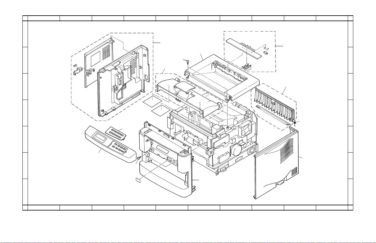
FIG. 1 COVERS
A
5B5
5B5-1
BCDEFGHI J
1
5
3
2
B30
8
3
6
7
4
9
10
5
1
6
B3
2
4
7
A
BCDEFGHI J
– 2 –
1
2
3
4
5
6
7
FIG. 1 COVERS
Ref.
No.
'
1 5B507080 KEY BOARD ASS’Y 1
2 5B507350 COVER FRONT 1
3 5B507360 COVER TOP 1
4 5B507370 COVER RIGHT 1
5 5B507380 COVER LEFT ASS’Y 1
6 5B407180 FD ASS’Y 1
7 5B507400 COVER REAR ASS’Y 1
8 5B507410 LID TOP ASS’Y 1
9 5B507420 SPRING COVER 1
'
10 5B507090 PANEL ENGLISH 1
DescriptionPart. No.SP
Quantity
Ref.
No.
5B5
5B5-1
DescriptionPart. No.SP
Quantity
• Parts with "•" are component parts or sub-assemblies of the
assembly appearing immediately above them.
• Parts with "'" indicates the service parts.
– 3 –
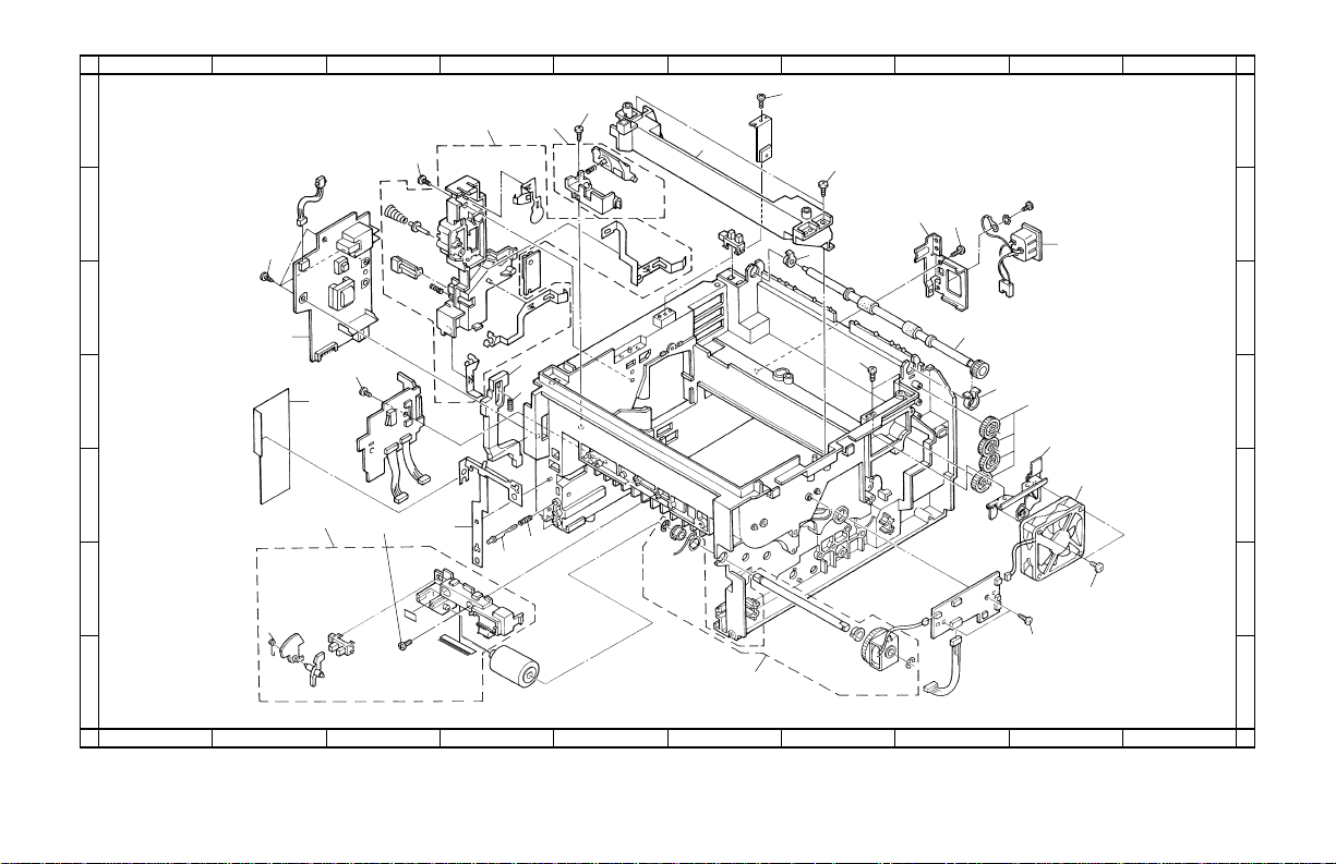
FIG. 2 FRAME UNIT
A
1
5B5
BCDEFGHI J
1
B3
17
B3
A03
B3
1
B3
2
B3
6
13
B3
12
3
16
B2
4
2
14
15
B3
5
A02
B3
3
11
10
6
7
A
BCDEFGHI J
A01
7
5
8
4
9
C2
B3
2
3
4
5
6
7
– 4 –

FIG. 2 FRAME UNIT
Ref.
No.
1 5B508030 COVER HV ASS’Y1
2 5B508500 SHEET HI VOLTAGE 1
3 5B507580 PLATE EARTH EF 1
4 5B508170 BRACKET FAN 1
5 5B108350 BUSH FD R 1
6 5B507670 BUSH FD L 1
7 5B507510 ROLLER FD 1
8 5A210270 GEAR MFEED Z25 4
' 9 5B507150 FAN MOTOR 1
10 5B508520 PIN SIZE SELECT 1
11 5B507590 SPRING SIZE SELECT 1
12 5B508140 CONN.CORD ASS’Y1
13 5B508350 BRACKET INLET 1
14 5B508660 ROD INTER LOCK A 1
15 5B107340 SPRING INTER LOCK 1
' 16 5B507140 TRANS ASS’Y1
17 5B508420 FRAME MID 1
' A01 5B507160 MP CLUTCH ASS’Y1
A02 5B507920 MP BRACKET ASS’Y1
A03 5B507660 DLP LOCK ASS’Y1
DescriptionPart. No.SP
Quantity
Ref.
No.
5B5
DescriptionPart. No.SP
Quantity
• Parts with "•" are component parts or sub-assemblies of the
assembly appearing immediately above them.
• Parts with "'" indicates the service parts.
– 5 –
 Loading...