

Page 1

DP-110
SERVICE
MANUAL
Published in June 2009
843LJ111
3LJSM061
Rev.1
Page 2

CAUTION
RISK OF EXPLOSION IF BATTERY IS REPLACED BY AN INCORRECT TYPE. DISPOSE OF
USED BATTERIES ACCORDING TO THE INSTRUCTIONS.
It may be illegal to dispose of this battery into the municipal waste stream. Check with your local
solid waste officials for details in your area for proper disposal.
ATTENTION
IL Y A UN RISQUE D’EXPLOSION SI LA BATTERIE EST REMPLACEE PAR UN MODELE DE
TYPE INCORRECT. METTRE AU REBUT LES BATTERIES UTILISEES SELON LES INSTRUCTIONS DONNEES.
Il peut être illégal de jeter les batteries dans des eaux d’égout municipales. Vérifiez avec les fonctionnaires municipaux de votre région pour les détails concernant des déchets solides et une mise
au rebut appropriée.
Page 3

Revision history
Revision Date Replaced pages Remarks
1 25 June 2009 1-1-1, 1-3-1 to 1-3-14, 1-5-2, 2-2-1
Page 4

This page is intentionally left blank.
Page 5

Safety precautions
This booklet provides safety warnings and precautions for our service personnel to ensure the safety of
their customers, their machines as well as themselves during maintenance activities. Service personnel
are advised to read this booklet carefully to familiarize themselves with the warnings and precautions
described here before engaging in maintenance activities.
Page 6
Safety warnings and precautions
Various symbols are used to protect our service personnel and customers from physical danger and
to prevent damage to their property. These symbols are described below:
DANGER: High risk of serious bodily injury or death may result from insufficient attention to or incorrect
compliance with warning messages using this symbol.
WARNING: Serious bodily injury or death may result from insufficient attention to or incorrect compliance
with warning messages using this symbol.
CAUTION: Bodily injury or damage to property may result from insufficient attention to or incorrect
compliance with warning messages using this symbol.
Symbols
The triangle ( ) symbol indicates a warning including danger and caution. The specific point
of attention is shown inside the symbol.
General warning.
Warning of risk of electric shock.
Warning of high temperature.
indicates a prohibited action. The specific prohibition is shown inside the symbol.
General prohibited action.
Disassembly prohibited.
indicates that action is required. The specific action required is shown inside the symbol.
General action required.
Remove the power plug from the wall outlet.
Always ground the copier.
Page 7

1.Installation Precautions
WARNING
• Do not use a power supply with a voltage other than that specified. Avoid multiple connections to
one outlet: they may cause fire or electric shock. When using an extension cable, always check
that it is adequate for the rated current. .............................................................................................
• Connect the ground wire to a suitable grounding point. Not grounding the copier may cause fire or
electric shock. Connecting the earth wire to an object not approved for the purpose may cause
explosion or electric shock. Never connect the ground cable to any of the following: gas pipes,
lightning rods, ground cables for telephone lines and water pipes or faucets not approved by the
proper authorities. ............................................................................................................................
CAUTION:
• Do not place the copier on an infirm or angled surface: the copier may tip over, causing injury. .......
• Do not install the copier in a humid or dusty place. This may cause fire or electric shock. ................
• Do not install the copier near a radiator, heater, other heat source or near flammable material.
This may cause fire. .........................................................................................................................
• Allow sufficient space around the copier to allow the ventilation grills to keep the machine as cool
as possible. Insufficient ventilation may cause heat buildup and poor copying performance. ...........
• Always handle the machine by the correct locations when moving it. ...............................................
• Always use anti-toppling and locking devices on copiers so equipped. Failure to do this may cause
the copier to move unexpectedly or topple, leading to injury. ...........................................................
• Avoid inhaling toner or developer excessively. Protect the eyes. If toner or developer is accidentally ingested, drink a lot of water to dilute it in the stomach and obtain medical attention immediately. If it gets into the eyes, rinse immediately with copious amounts of water and obtain medical
attention. ......................................................................................................................................
• Advice customers that they must always follow the safety warnings and precautions in the copier’s
instruction handbook. .....................................................................................................................
Page 8
2.Precautions for Maintenance
WARNING
• Always remove the power plug from the wall outlet before starting machine disassembly. ...............
• Always follow the procedures for maintenance described in the service manual and other related
brochures. .......................................................................................................................................
• Under no circumstances attempt to bypass or disable safety features including safety mechanisms
and protective circuits. .....................................................................................................................
• Always use parts having the correct specifications. ..........................................................................
• Always use the thermostat or thermal fuse specified in the service manual or other related brochure when replacing them. Using a piece of wire, for example, could lead to fire or other serious
accident. ..........................................................................................................................................
• When the service manual or other serious brochure specifies a distance or gap for installation of a
part, always use the correct scale and measure carefully. ................................................................
• Always check that the copier is correctly connected to an outlet with a ground connection. .............
• Check that the power cable covering is free of damage. Check that the power plug is dust-free. If it
is dirty, clean it to remove the risk of fire or electric shock. ..............................................................
• Never attempt to disassemble the optical unit in machines using lasers. Leaking laser light may
damage eyesight. ...........................................................................................................................
• Handle the charger sections with care. They are charged to high potentials and may cause electric
shock if handled improperly. ............................................................................................................
CAUTION
• Wear safe clothing. If wearing loose clothing or accessories such as ties, make sure they are
safely secured so they will not be caught in rotating sections. ..........................................................
• Use utmost caution when working on a powered machine. Keep away from chains and belts. ........
• Handle the fixing section with care to avoid burns as it can be extremely hot. ..................................
• Check that the fixing unit thermistor, heat and press rollers are clean. Dirt on them can cause
abnormally high temperatures. ........................................................................................................
Page 9
• Do not remove the ozone filter, if any, from the copier except for routine replacement. ....................
• Do not pull on the AC power cord or connector wires on high-voltage components when removing
them; always hold the plug itself. .....................................................................................................
• Do not route the power cable where it may be stood on or trapped. If necessary, protect it with a
cable cover or other appropriate item. .............................................................................................
• Treat the ends of the wire carefully when installing a new charger wire to avoid electric leaks. ........
• Remove toner completely from electronic components. ...................................................................
• Run wire harnesses carefully so that wires will not be trapped or damaged. ....................................
• After maintenance, always check that all the parts, screws, connectors and wires that were
removed, have been refitted correctly. Special attention should be paid to any forgotten connector,
trapped wire and missing screws. ...................................................................................................
• Check that all the caution labels that should be present on the machine according to the instruction
handbook are clean and not peeling. Replace with new ones if necessary. ......................................
• Handle greases and solvents with care by following the instructions below: .....................................
· Use only a small amount of solvent at a time, being careful not to spill. Wipe spills off completely.
· Ventilate the room well while using grease or solvents.
· Allow applied solvents to evaporate completely before refitting the covers or turning the power
switch on.
· Always wash hands afterwards.
• Never dispose of toner or toner bottles in fire. Toner may cause sparks when exposed directly to
fire in a furnace, etc. .......................................................................................................................
• Should smoke be seen coming from the copier, remove the power plug from the wall outlet imme-
diately. ............................................................................................................................................
3.Miscellaneous
WARNING
• Never attempt to heat the drum or expose it to any organic solvents such as alcohol, other than the
specified refiner; it may generate toxic gas. .....................................................................................
Page 10

This page is intentionally left blank.
Page 11

CONTENTS
1-1 Specifications
1-1-1 Specifications..........................................................................................................................................1-1-1
1-1-2 Parts names............................................................................................................................................1-1-2
1-1-3 Machine cross section ............................................................................................................................1-1-3
1-2 Installation
1-2-1 Installation environment ..........................................................................................................................1-2-1
1-2-2 Unpacking ...............................................................................................................................................1-2-2
(1) Unpacking .........................................................................................................................................1-2-2
(2) Removing the tapes and the spacer..................................................................................................1-2-3
1-3 Maintenance Mode
1-3-1 Maintenance mode .................................................................................................................................1-3-1
(1) Executing a maintenance item ..........................................................................................................1-3-1
(2) Maintenance modes item list.............................................................................................................1-3-2
(3) Contents of the maintenance mode items .........................................................................................1-3-3
1-4 Troubleshooting
1-4-1 Original misfeed detection ......................................................................................................................1-4-1
(1) Original misfeed indication ................................................................................................................1-4-1
(2) Original misfeed detection conditions................................................................................................1-4-2
(3) Paper misfeeds .................................................................................................................................1-4-3
1-4-2 Electric problems ....................................................................................................................................1-4-4
1-4-3 Mechanical problems ..............................................................................................................................1-4-6
1-5 Assembly and Disassembly
1-5-1 Precautions for assembly and disassembly............................................................................................1-5-1
(1) Precautions .......................................................................................................................................1-5-1
1-5-2 Outer covers ...........................................................................................................................................1-5-2
(1) Detaching and refitting the DP rear cover and DP front cover ..........................................................1-5-2
1-5-3 PWBs ......................................................................................................................................................1-5-3
(1) Detaching and refitting the DP driver PWB .......................................................................................1-5-3
1-5-4 Feed section ...........................................................................................................................................1-5-4
(1) Detaching and refitting the feed pulley and forwarding pulley...........................................................1-5-4
(2) Detaching and refitting the separation pad assembly .......................................................................1-5-7
2-1 Mechanical construction
2-1-1 Original feed section ...............................................................................................................................2-1-1
(1) Original conveying section ................................................................................................................2-1-2
2-1-2 Original switchback/eject sections ..........................................................................................................2-1-3
2-2 Electrical Parts Layout
2-2-1 Electrical parts layout..............................................................................................................................2-2-1
(1) Electrical parts layout ........................................................................................................................2-2-1
2-3 Operation of the PWBs
2-3-1 DP driver PWB........................................................................................................................................2-3-1
2-4 Appendixes
2-4-1 Appendixes .............................................................................................................................................2-4-1
(1) Wiring diagram ..................................................................................................................................2-4-1
Page 12

This page is intentionally left blank.
Page 13

1-1 Specifications
1-1-1 Specifications
Original feed method ......................Automatic feed
Supported original types ................. Sheet originals
Original sizes ..................................Maximum: Legal/A4
Minimum: Statement/A5
Original weights ..............................Simplex: 50 to 120 g/m
Duplex: 50 to 110 g/m
Loading capacity.............................50 sheets (50 to 80 g/m2) maximum
Power source..................................Electrically connected to the main machine.
Dimensions .....................................490 (W) × 339 (D) × 104 (H) mm
5/16 (W) × 13 3/8 (D) × 4 1/8" (H)
19
Weight.............................................3 kg or less/6.6 lbs. or less
NOTE: These specifications are subject to change without notice.
2
2
3LJ-1
1-1-1
Page 14
3LJ
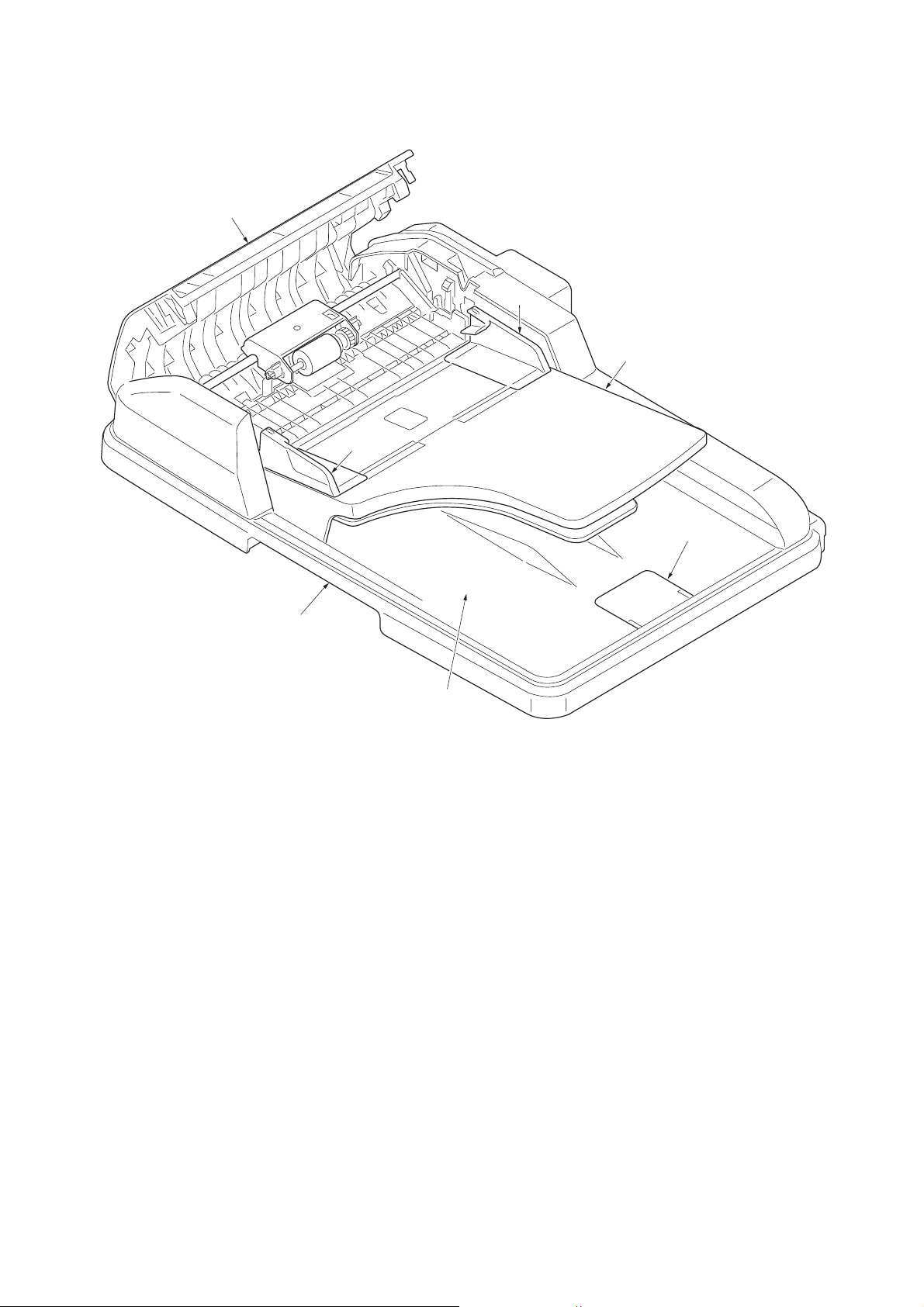
1-1-2 Parts names
1
2
3
2
5
6
4
Figure 1-1-1
1. Top cover
2. Original width guides
3. Original table
4. Original eject table
5. Original stopper
6. Opening handle
1-1-2
Page 15

1-1-3 Machine cross section
1
3LJ
2
3
Original path
Figure 1-1-2 Machine cross section
1. Original feed section
2. Original conveying section
3. Original switchback section
1-1-3
Page 16

3LJ
This page is intentionally left blank.
1-1-4
Page 17

3LJ
1-2 Installation
1-2-1 Installation environment
Installation location (Be based on the machine establishment place.)
Avoid direct sunlight or bright lighting. Ensure that the photo-conductor will not be exposed to direct sunlight or other
strong light when removing paper jams.
Avoid locations subject to high temperature and high humidity or low temperature and low humidity; an abrupt change in
the environmental temperature; and cool or hot, direct air.
Avoid places subject to dust and vibrations.
Choose a surface capable of supporting the weight of the machine.
Place the machine on a level surface (maximum allowance inclination: 1
Avoid air-borne substances that may adversely affect the machine or degrade the photo-conductor, such as mercury,
acidic of alkaline vapors, inorganic gasses, NOx, SOx gases and chlorine-based organic solvents.
Select a well-ventilated location.
°).
1-2-1
Page 18
3LJ
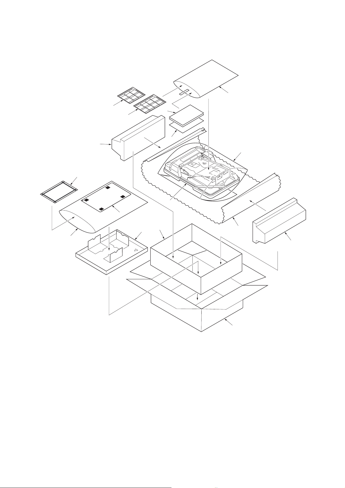
1-2-2 Unpacking
(1) Unpacking
12
16
15
5
10
9
8
11
14
13
2
1
7
3
4
1. Document processor (DP)
2. Plastic bag 300 × 800
3. Plastic sheet 800 × 800
4. Side pad R
5. Side pad L
6. Outer case
7. Inner case
8. Spacer tray
Caution: See the Installation Guide for installation.
1-2-2
6
Figure 1-2-1 Unpacking
9. Original mat
10. Adjustment original
11. Plastic bag 300 × 500
12. Plastic bag 240 × 350
13. Installation guide
14. Leaflets
15. Caution label (A)
16. Caution label (E)
Page 19
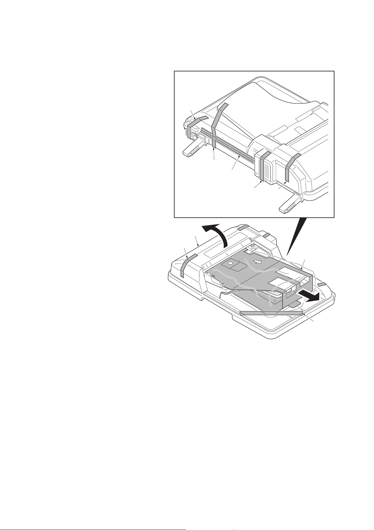
(2) Removing the tapes and the spacer
Procedure
1. Remove three tapes A.
2. Open the top cover and then remove the
spacer.
3. Remove four tapes B.
3LJ
Tape B
Tape B
Tape B
Top cover
Tape A
Tapes B
Figure 1-2-2
Tape A
Spacer
Tape A
1-2-3
Page 20

3LJ
This page is intentionally left blank.
1-2-4
Page 21

1-3 Maintenance Mode
1-3-1 Maintenance mode
The machine is equipped with a maintenance function which can be used to maintain and service the machine.
(1) Executing a maintenance item
Start
3LJ-1
Yes
Enter “10871087” using
the numeric keys.
Enter the maintenance item
number using the cursor left/right keys
or numeric keys.
Press the start key.
The selected maintenance item is run.
Press the stop key.
Repeat the same
maintenance item?
Maintenance mode is entered.
The maintenance item is
selected.
Yes
No
Run another maintenance
item?
No
Enter “001” using the cursor
left/right keys or numeric keys
and press the start key.
End
Maintenance mode is exited.
1-3-1
Page 22

3LJ-1
(2) Maintenance modes item list
Section Item
No.
General U001 Exiting the maintenance mode -
Optical U068 Adjusting the scanning position for originals from the DP 0/0
U070 Adjusting the DP magnification 0
U071 Adjusting the DP scanning timing 0/0/0/0/0
U072 Adjusting the DP center line 0/0
U087 Setting DP reading position modification operation 125/125/120
DP U203 Checking DP operation -
U243 Checking the operation of the DP motor solenoids and clutch -
U244 Checking the DP sensors -
Image
processing
Others
U404 Adjusting margins for scanning an original from the DP 3.0/2.5/3.0/4.0
U411 Adjusting the scanner automatically -
U905 Checking/clearing counts by optional devices -
U942 Setting of deflection for feeding from DP 0/0
Content of maintenance item Initial
setting
1-3-2
Page 23

(3) Contents of the maintenance mode items
3LJ-1
Maintenance
item No.
U001
U068
Description
Exiting the maintenance mode
Description
Exits the maintenance mode and returns to the normal copy mode.
Purpose
To exit the maintenance mode.
Method
Press the start key. The normal copy mode is entered.
Adjusting the scanning position for originals from the DP
Description
Adjusts the position for scanning originals from the DP. Performs the test copy at the four scanning positions
after adjusting.
Purpose
Used when the image fogging occurs because the scanning position is not proper when the DP is used. Run
U071 to adjust the timing of DP leading edge when the scanning position is changed.
Setting
1. Press the start key.
Display Description Setting
range
DP READ Starting position adjustment for
scanning originals
BLACK LINE Scanning position for the test copy
originals
2. Select [DP READ].
3. Change the setting using the cursor left/right keys or numeric keys.
When the setting value is increased, the scanning position moves to the right and it moves to the left
when the setting value is decreased.
4. Press the start key. The value is set.
5. Select [BLACK LINE] using the cursor up/down keys.
6. Select the scanning position using the cursor left/right keys or numeric keys.
7. Press the start key. The value is set.
8. Set the original (the one which density is known) in the DP and press the system menu/counter key. The
screen for the test copy mode is displayed.
9. Press the start key. Test copy is executed.
10. Perform the test copy at each scanning position with the setting value from 0 to 3 and check that no
black line appears and the image is normally scanned.
Completion
Press the stop key. The screen for selecting a maintenance item No. is displayed.
-33 to 33 0 0.086 mm
0 to 3 0 0.22 mm
Initial
setting
Change in
value per step
1-3-3
Page 24

3LJ-1
Maintenance
item No.
U070
Description
Adjusting the DP magnification
Description
Adjusts the DP original scanning speed.
Purpose
Make the adjustment if the magnification is incorrect in the auxiliary scanning direction when the DP is used.
Method
1. Press the start key.
Display Description Setting
range
CONVEY SPEED Magnification in the auxiliary scanning
-25 to 25 0 0.1%
Initial
setting
Change in
value per step
direction
Adjustment
1. Press the system menu/counter key.
2. Place an original on the DP and press the start key to make a test copy.
3. Press the system menu/counter key.
4. Change the setting value using the cursor left/right keys or numeric keys.
For copy example 1, increase the value. For copy example 2, decrease the value.
Original Copy
example 1
Copy
example 2
Figure 1-3-1
5. Press the start key. The value is set.
Caution
Check the copy image after the adjustment. If the image is still incorrect, perform the following adjustments in
maintenance mode.
U070
U071
(P.1-3-5)
U404
(P.1-3-11)
Completion
Press the stop key. The screen for selecting a maintenance item No. is displayed.
1-3-4
Page 25

3LJ-1
Maintenance
item No.
U071
Description
Adjusting the DP scanning timing
Description
Adjusts the DP original scanning timing.
Purpose
Make the adjustment if there is a regular error between the leading or trailing edges of the original and the
copy image when the optional DP is used.
Method
1. Press the start key.
2. Select the item to be adjusted using the cursor up/down keys.
Display Description Setting
range
Initial
setting
Change in
value per step
FRONT HEAD Leading edge registration (first page) -32 to 32 0 0.196 mm
FRONT TAIL Trailing edge registration (first page) -32 to 32 0 0.196 mm
BACK HEAD Leading edge registration (second page) -45 to 45 0 0.196 mm
BACK TAIL Trailing edge registration (second page) -45 to 45 0 0.196 mm
ROTATE Leading edge registration (rotate copying) -128 to 127 0 0.196 mm
Adjustment: Leading edge registration
1. Press the system menu/counter key.
2. Place an original on the DP and press the start key to make a test copy.
3. Press the system menu/counter key.
4. Change the setting value using the cursor left/right keys or numeric keys.
For copy example 1, increase the value. For copy example 2, decrease the value.
Original Copy
example 1
Copy
example 2
Figure 1-3-2
5. Press the start key. The value is set.
Caution
Check the copy image after the adjustment. If the image is still incorrect, perform the following adjustments in
maintenance mode.
U071
U404
(P.1-3-11)
1-3-5
Page 26

3LJ-1
Maintenance
item No.
U071
Description
Adjustment: Trailing edge registration
1. Press the system menu/counter key.
2. Place an original on the DP and press the start key to make a test copy.
3. Press the system menu/counter key.
4. Change the setting value using the cursor left/right keys or numeric keys.
For copy example 1, increase the value. For copy example 2, decrease the value.
Original
Copy
example 1
Copy
example 2
Figure 1-3-3
5. Press the start key. The value is set.
Caution
Check the copy image after the adjustment. If the image is still incorrect, perform the following adjustments in
maintenance mode.
U071
U404
(P.1-3-11)
Completion
Press the stop key. The screen for selecting a maintenance item No. is displayed.
1-3-6
Page 27

3LJ-1
Maintenance
item No.
U072
Description
Adjusting the DP center line
Description
Adjusts the scanning start position for the DP original.
Purpose
Make the adjustment if there is a regular error between the centers of the original and the copy image when
the optional DP is used.
Adjustment
1. Press the start key.
2. Select the item to be adjusted using the cursor up/down keys.
Display Description Setting
range
Initial
setting
Change in
value per step
FRONT Center line (first page) -39 to 39 0 0.086 mm
BACK Center line (second page) -39 to 39 0 0.086 mm
ROTATE Center line (rotate copying) -128 to 127 0 0.086 mm
3. Press the system menu/counter key.
4. Place an original on the DP and press the start key to make a test copy.
5. Press the system menu/counter key.
6. Change the setting value using the cursor left/right keys or numeric keys.
For copy example 1, increase the value. For copy example 2, decrease the value.
Reference
Original Copy
example 1
Copy
example 2
Figure 1-3-4
7. Press the start key. The value is set.
Caution
Check the copy image after the adjustment. If the image is still incorrect, perform the following adjustments in
maintenance mode.
U072
U404
(P.1-3-11)
Completion
Press the stop key. The screen for selecting a maintenance item No. is displayed.
1-3-7
Page 28

3LJ-1
Maintenance
item No.
U087
Description
Setting DP reading position modification operation
Description
The presence or absence of dust is determined by comparing the scan data of the original trailing edge and
that taken after the original is conveyed past the DP original scanning position. If dust is identified, the DP
original scanning position is adjusted for the following originals.
Purpose
When using DP, to solve the problem when black lines occurs due to the dust with respect to original reading
position.
Method
1. Press the start key.
2. Select the item to be set using the cursor up/down keys.
Display Description
CCD Setting of standard data when dust is detected.
BLACK LINE Initialization of original reading position.
Setting: Standard data when dust is detected
1. Select the item to be set using the cursor up/down keys.
2. Change the value using the cursor left/right keys or numeric keys.
Display Description Setting range Initial setting
CCD R Lowest density of the R regard as the dust 0 to 255 125
CCD G Lowest density of the G regard as the dust 0 to 255 125
CCD B Lowest density of the B regard as the dust 0 to 255 120
3. Press the start key. The value is set.
Setting: Initialization of original reading position
1. Select [CLEAR] using the cursor up/down keys.
2. Press the start key. The setting is cleared.
Completion
Press the stop key. The screen for selecting a maintenance item No. is displayed.
1-3-8
Page 29

3LJ-1
Maintenance
item No.
U203
U243
Description
Checking DP operation
Description
Simulates the original conveying operation separately in the DP.
Purpose
To check the DP operation.
Method
1. Press the start key.
2. Place an original in the DP if running this simulation with paper.
3. Select the speed to be operated using the cursor up/down keys.
Display Description
NORMAL SPEED Normal reading (600 dpi)
HIGH SPEED High-speed reading
4. Press the start key.
5. Select the item to be operated using the cursor up/down keys.
Display Description
CCD ADP (NON P) Without paper, single-sided original of CCD (continuous operation)
CCD ADP With paper, single-sided original of CCD
CCD RADP (NON P)
CCD RADP With paper, double-sided original of CCD
6. Press the start key. The operation starts.
7. To stop continuous operation, press the stop key.
Completion
Press the stop key. The screen for selecting a maintenance item No. is displayed.
Checking the operation of the DP motor solenoids and clutch
Description
Turns the motor, solenoids and clutch in the DP on.
Purpose
To check the operation of the DP motor, solenoids and clutch.
Method
1. Press the start key.
2. Select the item to be operated using the cursor up/down keys.
3. Press the start key. The operation starts.
Display Motor, solenoids and clutch
DP FEED MOT DP paper feed motor is turned on.
DP REV PRS SOL DP switchback pressure solenoid is turned on.
DP REV BRCH SOL DP switchback feedshift solenoid is turned on.
DP FEED CL DP paper feed clutch is turned on.
Without paper, double-sided original of CCD (continuous operation)
4. To stop operation, press the stop key.
Completion
Press the stop key when operation stops. The screen for selecting a maintenance item No. is displayed.
1-3-9
Page 30

3LJ-1
Maintenance
item No.
U244
Description
Checking the DP sensors
Description
Displays the status of the respective sensors in the DP.
Purpose
To check if respective sensors in the DP operate correctly.
Method
1. Press the start key.
2. Turn the respective sensors on and off manually to check the status.
When a sensor is detected to be in the ON position, the display for that sensor will be highlighted.
Display Sensors
TMG SW DP timing sensor
SET SW DP original sensor
DP OP SW DP open/close sensor
Completion
Press the stop key. The screen for selecting a maintenance item No. is displayed.
1-3-10
Page 31

3LJ-1
Maintenance
item No.
U404
Description
Adjusting margins for scanning an original from the DP
Description
Adjusts margins for scanning the original from the DP.
Purpose
Make the adjustment if margins are incorrect when the optional DP is used.
Caution
Before making this adjustment, ensure that the following adjustments have been made in maintenance mode.
(See the service manual
U402
for the machine.)
(See the service manual
U403
for the machine.)
U404
Adjustment
1. Press the start key.
2. Select the item to be adjusted using the cursor up/down keys.
Display Description
Setting
range
Initial
setting
Change in
value per step
A MARGIN Left margin 0 to 10.0 3.0 0.5 mm
B MARGIN Leading edge margin 0 to 10.0 2.5 0.5 mm
C MARGIN Right margin 0 to 10.0 3.0 0.5 mm
D MARGIN Trailing edge margin 0 to 10.0 4.0 0.5 mm
3. Press the system menu/counter key.
4. Place an original on the DP and press the start key to make a test copy.
5. Press the system menu/counter key.
6. Change the setting value using the cursor left/right keys.
Increasing the value makes the margin wider, and decreasing it makes the margin narrower.
DP leading edge margin
(3.0±1.5 mm)
DP left margin
(2.0±1.0 mm)
DP right margin
DP trailing edge margin
(2.0±1.0 mm)
(2.0±1.0 mm)
Figure 1-3-5
7. Press the start key. The value is set.
Completion
Press the stop key. The screen for selecting a maintenance item No. is displayed.
1-3-11
Page 32

3LJ-1
Maintenance
item No.
U411
Description
Adjusting the scanner automatically
Description
Uses the adjustment original suppled with DP and automatically adjusts the following items in the scanner and
the DP scanning sections.
Purpose
To perform automatic adjustment of various items in the scanner and the DP scanning sections.
Method
1. Press the start key.
Display Description Original to be used
for adjustment (P/N)
ADJUST TABLE Automatic adjustment in the scanner section:
Original size magnification, leading edge timing,
center line, input gamma, input gamma in monochrome mode and matrix
ADJUST DP Automatic adjustment in the DP scanning section:
Original size magnification, leading edge timing,
center line
Method: TABLE
1. Enter the target values which are shown on the specified original (P/N: 302FZ56990) executing maintenance item U425.
2. Set a specified original (P/N: 302FZ56990) on the platen.
3. Enter maintenance item U411.
4. Select [ADJUST TABLE] using the cursor up/down keys.
5. Press the start key. Auto adjustment starts.
When automatic adjustment has normally completed, [OK] is displayed. If a problem occurs during auto
adjustment, [NG XX] (XX is replaced by an error code) is displayed and operation stops. Should this
happen, determine the details of the problem and either repeat the procedure from the beginning, or
adjust the remaining items manually by running the corresponding maintenance items.
6. To return to the screen for selecting an item, press the stop key.
302FZ56990
303LJ57010
(Adjustment original
suppled with DP)
Method: DP
1. Select [ADJUST DP] using the cursor up/down keys.
2. Set a specified original (P/N: 303LJ57010) in the DP.
3. Press the start key. Auto adjustment starts.
When automatic adjustment has normally completed, [OK] is displayed. If a problem occurs during auto
adjustment, [NG XX] (XX is replaced by an error code) is displayed and operation stops. Should this
happen, determine the details of the problem and either repeat the procedure from the beginning, or
adjust the remaining items manually by running the corresponding maintenance items.
4. To return to the screen for selecting an item, press the stop key.
Completion
Press the stop key. The screen for selecting a maintenance item is displayed.
1-3-12
Page 33

3LJ-1
Maintenance
item No.
U905
U942
Description
Checking/clearing counts by optional devices
Description
Displays or clears the counts of DP.
Purpose
To check the use of DP. Also to clear the counts after replacing consumable parts.
Method
1. Press the start key.
Display Description
ADP No. of single-sided originals that has passed through the DP
RADP No. of double-sided originals that has passed through the DP
Clearing
1. Select the item to be cleared using the cursor up/down keys.
To clear the counts for all, select [ALL CLEAR].
2. Press the start key. The count is cleared.
Completion
Press the stop key. The screen for selecting a maintenance item No. is displayed.
Setting of deflection for feeding from DP
Description
Adjusts the deflection generated when the DP is used.
Purpose
Use this mode if an original non-feed jam, oblique feed or wrinkling of original occurs when the DP is used.
Setting
1. Press the start key.
2. Select the item to be adjusted using the cursor up/down keys.
Display Description Setting
range
REGIST TOP Deflection of single-sided original -31 to 31 0 0.098 mm
REGIST
BACK
3. Press the system menu/counter key.
4. Place an original on the DP and press the start key to make a test copy.
5. Press the system menu/counter key.
6. Change the setting value using the cursor left/right keys or numeric keys.
The greater the value, the larger the deflection; the smaller the value, the smaller the deflection.
If an original non-feed jam or oblique feed occurs, increase the setting value. If wrinkling of original
occurs, decrease the value.
7. Press the start key. The setting is set.
Completion
Press the stop key. The screen for selecting a maintenance item No. is displayed.
Deflection of double-sided original -31 to 31 0 0.098 mm
Initial
setting
Change in
value per step
1-3-13
Page 34

3LJ-1
This page is intentionally left blank.
1-3-14
Page 35

3LJ
1-4 Troubleshooting
1-4-1 Original misfeed detection
(1) Original misfeed indication
When an original jams, the machine immediately stops operation and a message is shown on the machine operation
panel.
To remove the jammed original, open the top cover.
To reset the original misfeed detection, open and close the top cover.
1-4-1
Page 36

3LJ
(2) Original misfeed detection conditions
DP document
sensor
DP timing
sensor
Figure 1-4-1
Section Jam code Conditions Specified
time
DP 70
No original feed
71
An original jam in the original conveying section 1
72
An original jam in the original conveying section 2
73
An original jam in the original switchback section
74
An original jam in the original switchback/feed section
78
Top cover open
The DP timing sensor does not turn on within specified time
during the first sheet feeding (Retry 5 times).
The DP timing sensor does not turn on within specified time
during the second sheet feeding (Retry 5 times).
The DP timing sensor does not turn off within specified time
of the DP paper feed motor turning on.
The DP timing sensor turns off within the specified time of
period of the DP paper feed motor turning on.
During original switchback operation, DP timing sensor does
not turn off within specified time of the DP paper feed motor
turning on.
The DP timing sensor does not turn on within specified time
of the DP timing sensor turning off.
The top cover is opened during original feeding.
The DP timing sensor turns on when starting the original
paper feed.
647 pulses
647 pulses
7487 pulses
1456 pulses
7487 pulses
4511 pulses
-
1-4-2
Page 37

(3) Paper misfeeds
3LJ
Problem
(1)
An original jams in
DP is indicated during copying (no original feed).
Jam code 70
(2)
An original jams in
DP is indicated during copying (a jam in
the original conveying section 1).
Jam code 71
(3)
An original jams in
DP is indicated during copying (a jam in
the original conveying section 2).
Jam code 72
(4)
An original jams
when the main power
switch is turned on.
Causes/check procedures
Defective DP timing sensor. Run maintenance item U244 and turn the DP timing sensor on
and off manually. Replace the sensor if indication of the corresponding sensor on the operation panel is not displayed in
reverse.
Check if the DP paper feed
motor malfunctions.
Check if the DP paper feed
clutch malfunctions.
Defective DP timing sensor. Run maintenance item U244 and turn the DP timing sensor on
Check if the DP paper feed
motor malfunctions.
Check if the DP paper feed
clutch malfunctions.
Defective DP timing sensor. Run maintenance item U244 and turn the DP timing sensor on
Check if the DP paper feed
motor malfunctions.
Check if the DP paper feed
clutch malfunctions.
A piece of paper torn from
an original is caught around
the DP timing sensor.
Defective DP timing sensor. Run maintenance item U244 and turn the DP timing sensor on
Run maintenance item U243 and select the DP paper feed motor
on the operation panel to be turned on and off. Check the status
and remedy if necessary.
Run maintenance item U243 and select the DP paper feed clutch
on the operation panel to be turned on and off. Check the status
and remedy if necessary.
and off manually. Replace the sensor if indication of the corresponding sensor on the operation panel is not displayed in
reverse.
Run maintenance item U243 and select the DP paper feed motor
on the operation panel to be turned on and off. Check the status
and remedy if necessary.
Run maintenance item U243 and select the DP paper feed clutch
on the operation panel to be turned on and off. Check the status
and remedy if necessary.
Remove any found.
and off manually. Replace the sensor if indication of the corresponding sensor on the operation panel is not displayed in
reverse.
Corrective measures
1-4-3
Page 38

3LJ
1-4-2 Electric problems
Problem Causes Check procedures/corrective measures
(1)
The DP paper feed
motor does not operate.
Connection failure with DP
connector.
Turn the main power switch off, investigate the DP connector connection, and firmly connect the DP connector.
DP connector
DP
(2)
The switchback pressure solenoid does
not operate.
Defective harness between
DP paper feed motor and
Reinsert the connector. Also check for continuity within the con-
nector harness. If none, remedy or replace the harness.
DP driver PWB (YC3), or
improper connector insertion.
Defective drive transmission system.
Defective DP paper feed
motor.
Check if the rollers and gears rotate smoothly. If not, grease the
bushings and gears. Check for broken gears and replace if any.
Run maintenance item U243 and check if the DP paper feed
motor operates. If not, replace the DP paper feed motor.
Defective DP driver PWB. Run maintenance item U243 and check if the motor operates. If
not, replace the DP driver PWB (see page 1-5-3).
Defective scanner PWB
(Main machine).
Run maintenance item U243 and check if the motor operates. If
not, replace the scanner PWB (Refer to the main machine’s ser-
vice manual).
Defective harness between
switchback pressure sole-
Reinsert the connector. Also check for continuity within the con-
nector harness. If none, remedy or replace the harness.
noid and DP driver PWB
(YC5), or improper connector insertion.
Defective switchback pressure solenoid.
Run maintenance item U243 and check if the switchback pressure
solenoid operates. If not, replace the switchback pressure sole-
noid.
Defective DP driver PWB. Run maintenance item U243 and check if the switchback pressure
solenoid operates. If not, replace the DP driver PWB (see page 1-
5-3).
Defective scanner PWB
(Main machine).
Run maintenance item U243 and check if the motor operates. If
not, replace the scanner PWB (Refer to the main machine’s ser-
vice manual).
1-4-4
Page 39

Problem Causes Check procedures/corrective measures
3LJ
(3)
The switchback feedshift solenoid does
not operate.
(4)
A message indicating
cover open is displayed when the top
cover is closed correctly.
(5)
An original jams
when the main power
switch is turned on.
Defective harness between
switchback feedshift solenoid and DP driver PWB
(YC6), or improper connector insertion.
Defective switchback feedshift solenoid.
Defective DP driver PWB. Run maintenance item U243 and check if the switchback feedshift
Defective scanner PWB
(Main machine).
Defective harness between
DP open/close sensor and
DP driver PWB (YC2), or
improper connector insertion.
Defective DP open/close
sensor.
A piece of paper torn from
an original is caught around
the DP timing sensor.
Defective DP timing sensor. Run maintenance item U244 and turn the DP timing sensor on
Reinsert the connector. Also check for continuity within the con-
nector harness. If none, remedy or replace the harness.
Run maintenance item U243 and check if the switchback feedshift
solenoid operates. If not, replace the switchback feedshift sole-
noid.
solenoid operates. If not, replace the DP driver PWB (see page 1-
5-3).
Run maintenance item U243 and check if the motor operates. If
not, replace the scanner PWB (Refer to the main machine’s ser-
vice manual).
Reinsert the connector. Also check for continuity within the con-
nector harness. If none, remedy or replace the harness.
Run maintenance item U244 and turn the DP open/close sensor.
on and off manually. Replace the sensor if indication of the corre-
sponding sensor on the operation panel is not displayed in
reverse.
Remove any found.
and off manually. Replace the sensor if indication of the corre-
sponding sensor on the operation panel is not displayed in
reverse.
1-4-5
Page 40

3LJ
1-4-3 Mechanical problems
Problem Causes/check procedures Corrective measures
(1)
No primary original feed.
Connection failure with DP connector. Turn the main power switch off, investigate
the DP connector connection, and firmly
connect the DP connector.
DP
DP connector
(2)
Originals jam.
The surfaces of the forwarding pulley, feed
pulley or separation pad are dirty with paper
powder.
Check if the forwarding pulley or the feed pul-
Check and clean them with isopropyl alcohol
if they are dirty (see page 1-5-4 or page 1-5-
7).
If so, replace (see page 1-5-4).
ley is deformed.
Electrical problem with the DP paper feed
See page 1-4-4.
motor.
Originals outside the specifications are used. Use only originals conforming to the specifi-
cations.
The surfaces of the forwarding pulley, feed
pulley or separation pad are dirty with paper
powder.
Check if the contact between the eject roller
Check and clean them with isopropyl alcohol
if they are dirty (see page 1-5-4 or page 1-5-
7).
Check visually and remedy if necessary.
and exit pulley is correct.
Check if the contact between the switchback
Check visually and remedy if necessary.
roller and switchback pulley is correct.
1-4-6
Page 41

3LJ
1-5 Assembly and Disass embly
1-5-1 Precautions for assembly and disassembly
(1) Precautions
Before starting disassembly, press the Power key on the operation panel to off. Make sure that the Power lamp is off
before turning off the main power switch. And then unplug the power cable from the wall outlet.
When handling PWBs (printed wiring boards), do not touch parts with bare hands.
The PWBs are susceptible to static charge.
Do not touch any PWB containing ICs with bare hands or any object prone to static charge.
When removing the hook of the connector, be sure to release the hook.
Take care not to get the cables caught.
To reassemble the parts, use the original screws. If the types and the sizes of screws are not known, refer to the PARTS
LIST.
1-5-1
Page 42

3LJ-1
1-5-2 Outer covers
(1) Detaching and refitting the DP rear cover and DP front cover
Procedure
1. Open the top cover.
2. Remove two screws.
3. Unhook the hook and then remove the DP
rear cover.
DP rear cover
Top cover
Screw
4. Unhook two hooks and then remove the DP
front cover.
Hook
DP rear cover
DP front cover
Screw
Figure 1-5-1
1-5-2
Hook
Figure 1-5-2
Page 43

1-5-3 PWBs
(1) Detaching and refitting the DP driver PWB
Follow the procedure below to check or replace the DP driver PWB.
Procedure
1. Remove the DP rear cover (See page 1-5-
2).
2. Remove eight connectors from the DP
driver PWB.
3. Remove the screw and then remove the DP
driver PWB.
4. Check or replace the DP driver PWB.
Refit all the removed parts.
YC7
YC8
YC1
Screw
Connectors
YC4
YC5
YC6
DP driver PWB
3LJ
YC2
YC3
DP driver PWB
Figure 1-5-3
1-5-3
Page 44

3LJ
1-5-4 Feed section
(1) Detaching and refitting the feed pulley and forwarding pulley
Follow the procedure below to clean or replace the feed pulley or forwarding pulley.
Procedure
1. Remove the DP rear cover and DP front
cover (See page 1-5-2).
2. Remove the stopper.
3. Remove the bush.
4. Remove the stopper A and then remove the
DP paper feed clutch.
5. Remove the stopper B and then remove the
PF collar, spring, spring collar S, pin and
bush from the PF shaft.
PF shaft
Bush
DP paper
feed clutch
Figure 1-5-4
Pin
Stopper A
Bush
Stopper
Spring collar S
Spring
PF collar
Stopper B
1-5-4
PF shaft
Spring
PF shaft
Figure 1-5-5
Page 45

6. Remove the forwarding pulley assembly.
3LJ
Forwarding pulley assembly
Detaching the feed pulley
7. Remove the stopper A.
8. Remove the feed pulley assembly from the
LF holder.
9. Remove the stopper B.
10. Remove the PF collar, spring, spring collar S
and pin from the PF shaft.
11. Remove the feed pulley, one-way clutch, PF
pulley gear and pin from the PF shaft.
One-way clutch
PF pulley gear
Pin
Feed pully
PF shaft
Feed pulley
assembly
Figure 1-5-6
Spring
Spring collar S
Pin
Stopper B
PF collar
Stopper A
LF holder
Figure 1-5-7
1-5-5
Page 46

3LJ
Detaching the forwarding pulley
12. Remove the PF stopper from the LF holder.
13. Remove the stopper.
14. Pull out the LF shaft and then remove the LF
gear 18, forwarding feed joint gear and forwarding pulley.
15. Clean or replace the feed pulley and forwarding pulley.
Refit all the removed parts.
LF holder
PF stopper
Stopper
LF shaft
LF gear 18
Figure 1-5-8
Forwarding
pulley
Forwarding
feed joint gear
1-5-6
Page 47

(2) Detaching and refitting the separation pad assembly
Follow the procedure below to clean or replace the separation pad assembly.
Procedure
1. Remove the forwarding pulley assembly
(See page 1-5-4).
2. Remove the separation pad assembly.
3. Clean or replace the separation pad assembly.
Refit all the removed parts.
3LJ
Separation pad
assembly
Figure 1-5-9
1-5-7
Page 48

3LJ
This page is intentionally left blank.
1-5-8
Page 49

3LJ
2-1 Mechanical construction
2-1-1 Original feed section
The original feed section consists of the parts shown in figure. An original placed on the original table is conveyed to the
original conveying section. Original is fed by the rotation of the forwarding pulley and feed pulley.
7
9
8
Figure 2-1-1 Original feed section
(1) Forwarding pulley
(2) Feed pulley
(3) LF holder
(4) PF stopper
(5) Front separation pad
(6) LF friction plate
(7) Separation pad
2
3
4
5
6
12
1
10
11
13
(8) Separation mount
(9) Upper guide
(10) Loop guide
(11) Original sensor
(12) Actuator (Original sensor)
(13) Original table
]
DP driver PWB
DP paper
feed
clutch
DP original
sensor
DP paper
feed motor
FEEDCL
ORGSWN
DPMOT1A, DPMOT2A
DPMOT1B, DPMOT2B
YC6-2
YC2-6
YC3-1,2,3,4
Figure 2-1-2Original feed section block diagram
2-1-1
Page 50

3LJ
(1) Original conveying section
The original conveying section consists of the parts shown in figure. A conveyed original is scanned by the optical section
(CCD) of main machine when it passes through the DP contact glass of main machine.
6
5
1
2
3
4
DP paper
feed
clutch
DP
timing
sensor
7
Figure 2-1-3Original conveying section
(1) Conveying roller A
(2) Conveying pulley
(3) Conveying bottom
(4) Reading guide
(5) DP timing sensor
(6) Actuator (DP timing sensor)
(7) DP contact glass (main machine)
DP paper
feed motor
FEEDCL
DPMOT1A, DPMOT2A
DPMOT1B, DPMOT2B
DP driver PWB
YC6-2
YC3-1,2,3,4
2-1-2
Figure 2-1-4Original conveying section block diagram
TIMSWN
YC2-9
Page 51

3LJ
2-1-2 Original switchback/eject sections
The original switchback/eject sections consists of the parts shown in figure. An original of which scanning is complete is
ejected to the original eject table by the eject roller. In the case of duplex switchback scanning, an original is conveyed
temporarily to the switchback tray and conveyed again to the original conveying section by the switchback roller.
10
11
8
9
1
2
3
Figure 2-1-5Original switchback/eject sections
(1) Conveying roller B
(2) Conveying pulley
(3) DP base
(4) Eject roller
(5) Exit pulley
(6) PF housing
(7) Original eject table
(8) Switchback guide
(9) Switchback roller
(10) Switchback pulley
(11) Switchback pulley mount
(12) Switchback tray
12
4
6
5
7
DP switchback
pressure solenoid
DP switchback
feedshift solenoid
DP
timing
sensor
DP paper
feed motor
DPMOT1A, DPMOT2A
DPMOT1B, DPMOT2B
Figure 2-1-6Original switchback/eject sections block diagram
PRESOLN
RELSOLN
REVSOL
TIMSWN
DP driver PWB
YC4-2
YC4-3
YC5-2
YC3-1,2,3,4
YC2-9
2-1-3
Page 52

3LJ
This page is intentionally left blank.
2-1-4
Page 53

2-2 Electrical Parts Layout
2-2-1 Electrical parts layout
(1) Electrical parts layout
3LJ-1
6
4
3
2
5
Machine front Machine inside Machine rear
8
7
1
Figure 2-2-1 Electrical parts layout
1. DP driver PWB............................................. Consists the solenoids and clutch driver circuit and wiring relay circuit.
2. DP original sensor........................................ Detects the presence of an original.
3. DP timing sensor.......................................... Detects the original scanning timing.
4. DP open/close sensor.................................. Detects the opening/closing of the DP.
5. DP paper feed motor.................................... Drives the original feed section.
6. DP paper feed clutch ................................... Controls the drive of the forwarding pulley and feed pulley.
7. DP switchback feedshift solenoid ................ Operates the switchback guide.
8. DP switchback pressure solenoid ................ Operates the switchback pulley.
2-2-1
Page 54

3LJ
This page is intentionally left blank.
2-2-2
Page 55

2-3 Operation of the PWBs
2-3-1 DP driver PWB
3LJ
DP paper
feed motor
DP driver PWB
MOT1A,MOT2A
+3.3V1
FEEDCL
MOT1B,MOT2B
Transistor
Transistors
Transistor
OPSWN
TIMSWN
REVSOL
ORGSWN
PRESOLN, RELSOLN
DP paper feed clutch
DP switchback
pressure solenoid
DP switchback
feedshift solenoid
DP open/close sensor
DP timing sensor
DP original sensor
+24V4
Main machine
Motor driver
Scanner PWB
CPU
Figure 2-3-1 DP driver PWB block diagram
2-3-1
Page 56

3LJ
1
YC7YC1
2
1
26
YC8
9
10
1
3
1
YC6 YC4
2
YC5
2
1
1
9
YC2
1
Figure 2-3-2DP driver PWB silk-screen diagram
Connector Pin No. Signal I/O Voltage Description
YC1 1 MOT1A I 0/24 V DC (pulse) DP paper feed motor drive pulse
Connected to
the scanner
PWB
(Machine)
2 MOT2B I 0/24 V DC (pulse) DP paper feed motor drive pulse
3 MOT1B I 0/24 V DC (pulse) DP paper feed motor drive pulse
4 MOT2A I 0/24 V DC (pulse) DP paper feed motor drive pulse
5 +24V4 I 24 V DC 24 V DC power source
6 GND - - Ground
YC2 1 PILED O 3.3 V DC 3.3 V DC power source
Connected to
the DP open/
close sensor, DP original sensor
and DP timing sensor
2 GND - - Ground
3 OPSWN I 0/3.3 V DC DP open/close sensor: On/Off
4 PILED O 3.3 V DC 3.3 V DC power source
5 GND - - Ground
6 ORGSWN I 0/3.3 V DC DP original sensor: On/Off
7 PILED O 3.3 V DC 3.3 V DC power source
8 GND - - Ground
9 TIMSWN I 0/3.3 V DC DP timing sensor: On/Off
YC3 1 MOT1A O 0/24 V DC (pulse) DP paper feed motor drive pulse
Connected to
the DP paper
feed motor
2 MOT2B O 0/24 V DC (pulse) DP paper feed motor drive pulse
3 MOT1B O 0/24 V DC (pulse) DP paper feed motor drive pulse
4 MOT2A O 0/24 V DC (pulse) DP paper feed motor drive pulse
YC4 1 +24V4 O 24 V DC 24 V DC power source
Connected to
the DP
switchback
2 PRESOLN O 0/24 V DC DP switchback pressure solenoid (Press): On/Off
3 RELSOLN O 0/24 V DC
DP switchback pressure solenoid: (Release) On/Off
pressure
solenoid
YC5 1 +24V4 O 24 V DC 24 V DC power source
Connected to
2 REVSOL O 0/24 V DC DP switchback feedshift solenoid: On/Off
the DP
switchback
feedshift
solenoid
YC6 1 +24V4 O 24 V DC 24 V DC power source
Connected to
2 FEEDCL O 0/24 V DC DP paper feed clutch: On/Off
the DP paper
feed clutch
4
YC3
1
2-3-2
Page 57

Connector Pin No. Signal I/O Voltage Description
YC7 1 +24V4 I 24 V DC 24 V DC power source
Connected to
the scanner
PWB (Main
machine)
YC8 1 +3.3V1 I 3.3 V DC 3.3 V DC power source
Connected to
the scanner
PWB (Main
machine)
2 GND - - Ground
2 GND - - Ground
3 TIMSWN O 0/3.3 V DC DP timing sensor: On/Off
4 ORGSWN O 0/3.3 V DC DP original sensor: On/Off
5 OPSWN O 0/3.3 V DC DP open/close sensor: On/Off
6 DPDETN O 0/3.3 V DC
7 RELSOLN I 0/3.3 V DC
8 PRESOLN I 0/3.3 V DC DP switchback pressure solenoid (Press): On/Off
9 REVSOL I 0/3.3 V DC DP switchback feedshift solenoid: On/Off
10 FEEDCL I 0/3.3 V DC DP paper feed clutch: On/Off
DP installation detection signal
DP switchback pressure solenoid: (Release) On/Off
3LJ
2-3-3
Page 58

3LJ
This page is intentionally left blank.
2-3-4
Page 59

2-4 Appendixes
2-4-1 Appendixes
(1) Wiring diagram
3LJ
DP paper
feed clutch
DP paper
feed motor
Main machine
4
4
DPMOT2B
3
3
DPMOT1B
2
2
DPMOT2A
1
1
DPMOT1A
2
2
FEEDCL
1
1
+24V4
YC109
Scanner PWB
1
2
1
2
1
2
GND
+24V4
1
2
YC7
3
4
3
4
YC108
12345
12345
1615141312
1615141312
MOT1A
MOT1A
MOT2B
MOT2B
12345
12345
YC1
6
6
11
11
+24V4
GND
6
6
YC105
123456789
123456789
987654321
10
987654321
10
+3.3V1
GND
TIMSWN
ORGSWN
OPSWN
DPDETN
RELSOLN
123456789
123456789
YC8
10
10
PRESOLN
REVSOL
FEEDCL
10
10
DP open/close
sensor
DP original
sensor
DP timing
sensor
DP switchback
feedshift
solenoid
DP switchback
pressure
solenoid
3
3
2
2
1
1
3
3
2
2
1
1
3
3
2
2
1
1
2
2
REVSOL
1
1
+24V4
3
3
RELSOLN
2
2
PRESOLN
+24V4
YC4 YC5 YC6 YC3
1
1
DP driver PWB
(+3.3V1)
1
1
PI LED
2
2
GND
3
3
OPSWN
(+3.3V1)
4
4
PI LED
5
5
GND
6
6
ORGSWN
1
3
2
2
3
1
(+3.3V1)
PI LED
GND
TIMSWN
YC2
7
7
8
8
9
9
2-4-1
Page 60

3LJ
This page is intentionally left blank.
2-4-2
Page 61

Page 62

 Loading...