

Page 1
DOWNTOWN 125i
Cortesia de/ Courtesy of: www.batmotos.com
Cortesia de/ Courtesy of: www.batmotos.com
All rights reserved. Any reproduction or
permission of KWANG YANG Motor Co., Ltd.
By KWANG YANG Motor Co., Ltd.
1st Edition, April 2009
unauthorized use without the written
is expressly prohibited.
T100-LFA7-A2
Page 2

PREFACE
C
C
Cortesia de/ Courtesy of: www.batmotos.com
Cortesia de/ Courtesy of: www.batmotos.com
DOWNTOWN 125i
TABLE OF CONTENTS
This Service Manual describes the
technical features and servicing
procedures for the KYMCO
Downtown 125i.
Section 1 contains the precautions for
all operations stated in this manual.
Read them carefully before any
operation is started.
Section 2 is the removal/installation
procedures for the frame covers which
are subject to removal/installation
frequency during maintenance and
servicing operations.
Section 3 describes the inspection/
adjustment procedures, safety rules
and service information for each part,
starting from periodic maintenance.
Sections 5 to 11 give instructions for
disassembly, assembly and
adjustment of engine parts. Section
13-14 is the AFI system. Section 15 to
16 is the removal/ installation of
chassis. Section 17 to 20 states the
testing and measuring methods of
electrical equipment.
Most sections start with an assembly
or system illustration and
troubleshooting for the section. The
subsequent pages give detailed
procedures for the section.
The information and contents
included in this manual may be
different from the motorcycle in case
specifications are changed.
KWANG YANG MOTOR CO., LTD.
QUALITY TECHNOLOGY DEPT.
EDUCATION SECTION
GENERAL INFORMATION
EXHAUST MUFFLER/FRAME
COVERS
INSPECTION/ADJUSTMENT
LUBRICATION SYSTEM
ENGINE REMOVAL/INSTALLATION
CYLINDER HEAD/VALVES
ENGINE
CYLINDER/PISTON
DRIVE AND DRIVEN PULLEYS
FINAL REDUCTION
A.C. GENERATOR/STARTER
CLUTCH
CRANKCASE/CRANKSHAFT
COOLING SYSTEM
Fi DIAGNOSTIC TOOL OPERATION
FUEL INJECTION SYSTEM
CHASSIS
HANDLEBAR/FRONT
WHEEL/FRONT BRAKE/FRONT
SHOCK ABSORBER/STEERING
STEM
REAR BRAKE/REAR FORK/REAR
WHEEL/REAR SHOCK ABSORBER`
ELE
EQUIPMENT
BATTERY/CHARGING SYSTEM
TRI
IGNITION SYSTEM
AL
STARTING SYSTEM
LIGHTS/METERS/SWITCHES
1
2
3
4
5
6
7
8
9
10
11
12
13
14
15
16
17
18
19
20
Page 3
1. GENERAL INFORMATION
Cortesia de/ Courtesy of: www.batmotos.com
Cortesia de/ Courtesy of: www.batmotos.com
DOWNTOWN 125i
ENGINE SERIAL NUMBER
SPECIFICATIONS
SERVICE PRECAUTIONS
TORQUE VALUES
SPECIAL TOOLS....................................
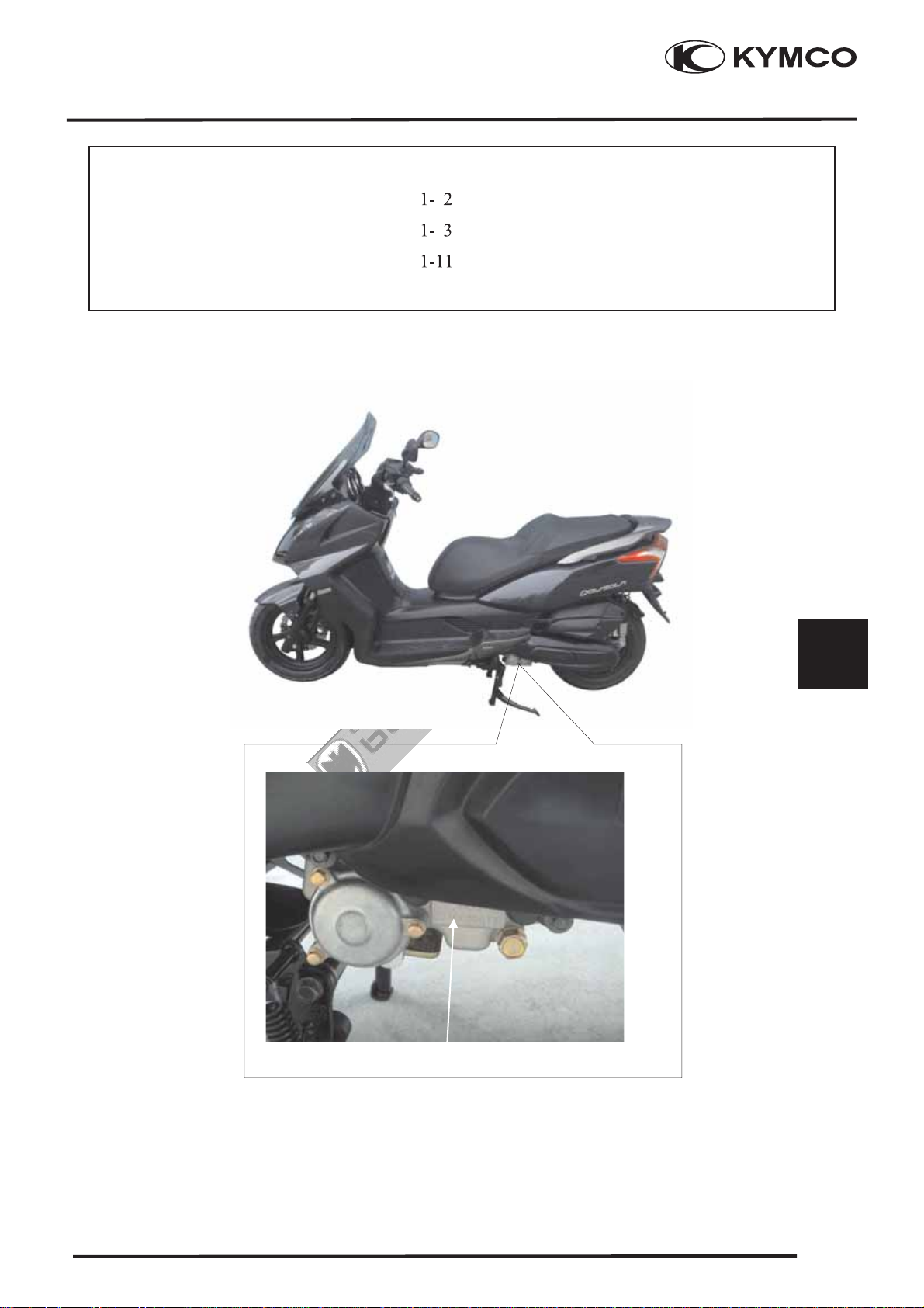
ENGINE SERIAL NUMBER
...................................
..................................
................... 1- 1
.....................
LUBRICATION POINTS..........................1-14
1-12
Location of Engine Serial Number
1
-1-
1-1
Page 4
1. GENERAL INFORMATION
Cortesia de/ Courtesy of: www.batmotos.com
Cortesia de/ Courtesy of: www.batmotos.com
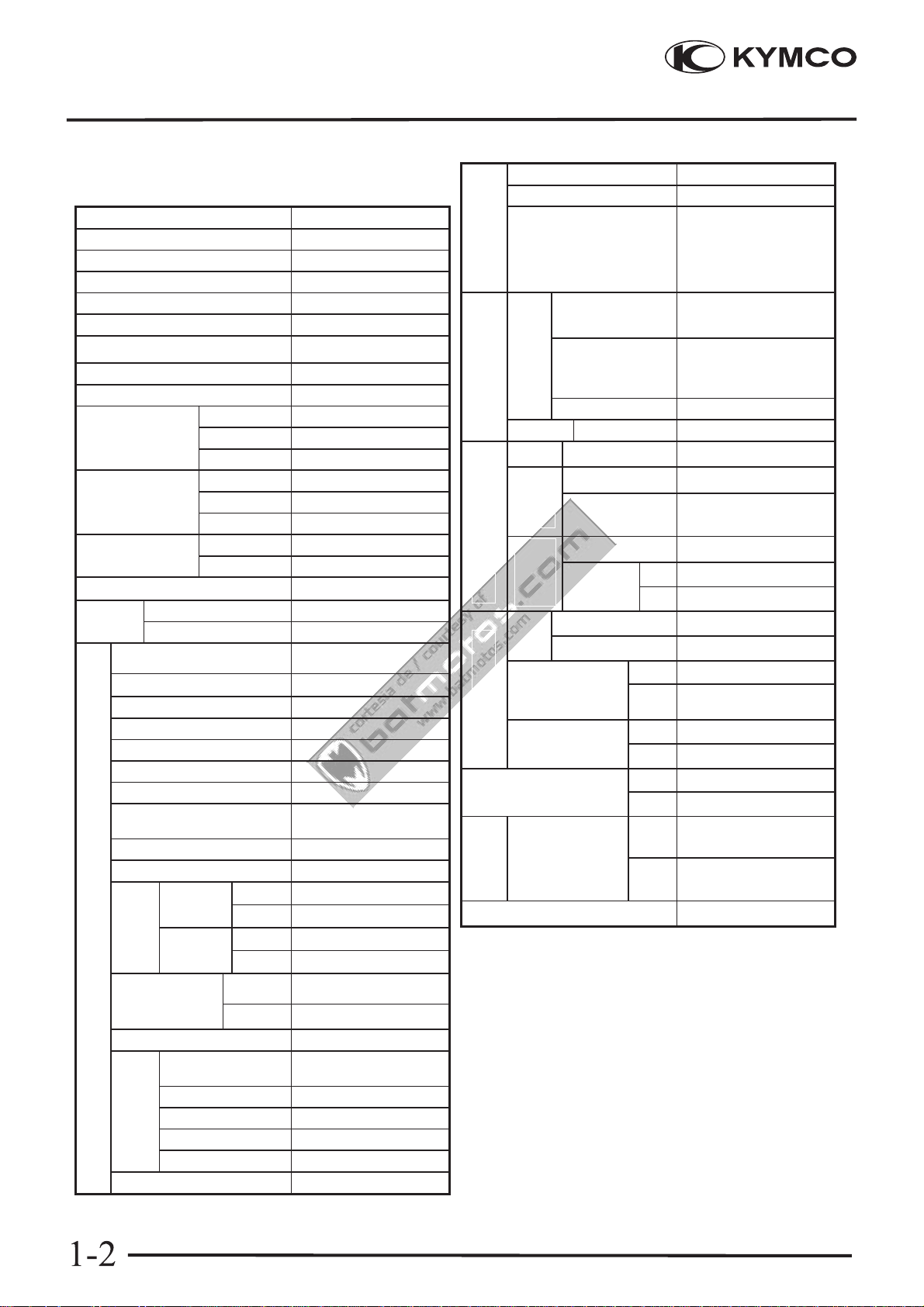
SPECIFICATIONS
Name DOWNTOWN125i
Model No. SK25AA
Overall length 2200mm
Overall width 800 mm
Overall height 1410 mm
Wheel base 1542 mm
Engine type
Displacement 124.8cc
Fuel Used 92# nonleaded gasoline
Front wheel 68
Net weight (kg) Rear wheel 96
Total 164
Front wheel 70
Gross weight(kg) Rear wheel 104
Total 178
Tires
RR Ground clearance 140 mm
Perform- Braking distance (m)
ance
Engine
Min. turning radius 2600mm
Starting system
Type
Cylinder arrangement Single cylinder
Combustion chamber type Semi-sphere
Valve arrangement O.H.C.4V
Bore x stroke (mm) 54 x 54.5
Compression ratio 11.7:1
Compression pressure
(kg/cm²)
Max .horsepower (ps/rpm) 15/8750~9000
Max. torque (kg m/rpm) 1.17/8500~8750
Port
timing
Valve Intake 0.10 mm
Front wheel 120/80-14
Rear wheel 150/70-13
Intake
(1mm)
Exhaust
(1mm)
Open 8 °BTDC
Close 31° BTDC
Open 32° BTDC
Close 6 °BTDC
O.H.C.
7.9m/30km/h
Starting motor
liquid cooled 4 stroke
15
DOWNTOWN 125i
Air cleaner type & No Paper element, wet
Fuel System
Fuel capacity 12.5 L
Throttle type
Ignition System
Electrical Equip.
Battery Capacity 12V10AH
Power Drive System
Clutch Type Dry multi-disc clutch
Transmis-
sion Gear
Reduction
Gear
Front Caster angle 28°
Moving Device
Axle
Tire pressure
(kg/cm²)1
person
Turning Left 40?
angle
Brake system
type
Damping
Device
Suspension
type
Frame type PIPE UNDER BONE
Type
Spark plug
Sparkpluggap 0.6~0.7mm
Type Non-stage transmission
Operation
Type Two-stage reduction
Reduction 1st
ratio
Trail length 140mm
2nd
Front 2.0
Rear 2.25
Right 40?
Front Disk brake
Rear
Front Telescope
Rear DOUBLE SWING
Butterfly type
ECU
NGK CR7E
Automatic centrifugal
type
0.83~2.2
10.41
Disk brake
clearance Exhaust 0.10 mm
Idle speed (rpm) 1850rpm
Lubrication
System
Lubrication type
Oil pump type Inner/outer rotor type
Oil filter type Full-flow filtration
Oil capacity 1.2 L
Exchanging capacity 1.0 L
Cooling Type Liquid cooling
Forced pressure &
Wet sump
-2-
Page 5
1. GENERAL INFORMATION
Cortesia de/ Courtesy of: www.batmotos.com
Cortesia de/ Courtesy of: www.batmotos.com
SERVICE PRECAUTIONS
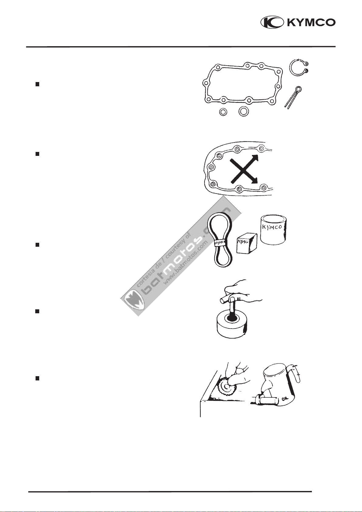
Make sure to install new gasket, O-rings, circlips,
cotter pins, etc. When reassembling.
.
When tightening bolts or nuts, begin with
larger-diameter to smaller ones at several
times, and tighten to specified torque
diagonally.
DOWNTOWN 125i
-
Use genuine parts and lubricants.
When servicing the motorcycle, be sure to
use special tools for removal and installation.
After diassembly, clean removed parts.
Lubricate sliding surfaces with engine oil
before reassembly.
-3-
1-3
Page 6

1. GENERAL INFORMATION
Cortesia de/ Courtesy of: www.batmotos.com
Cortesia de/ Courtesy of: www.batmotos.com
Apply or add designated greases and
lubricants to the specified lubrication points.
After reassembly, check all parts for proper
tightening and operation.
DOWNTOWN 125i
When two person work together, pay attention
to the mutual working safety.
Disconnect the battery negative (-) terminal
before operation.
When using a spanner or other tools, make
sure not to damage the motorcycle surface.
After operation, check all connecting points,
fasteners, and lines for proper connection
and installation.
When connecting the battery, the positive
(+) terminal must be connected first.
After connection, apply grease to
the battery terminals.
Terminal caps shall be installed securely.
-4-
Page 7
1. GENERAL INFORMATION
Cortesia de/ Courtesy of: www.batmotos.com
Cortesia de/ Courtesy of: www.batmotos.com
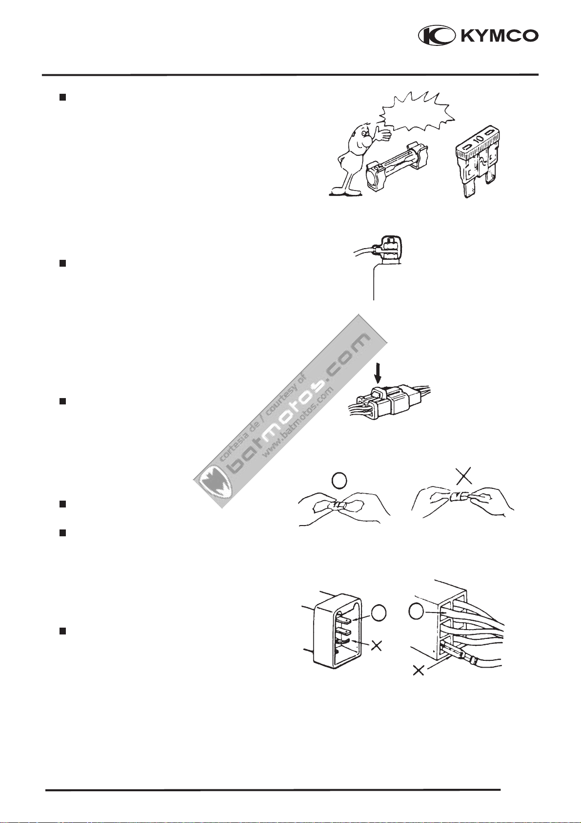
If the fuse is burned out, find the cause
and repair it. Replace it with a new one
according to the specified capacity.
After operation, terminal caps shall be
installed securely.
DOWNTOWN 125i
Confirm
Capacity
When taking out the connector, the lock
on the connector shall be released before
operation.
Hold the connector body when connecting
or disconnecting it.
Do not pull the connector wire.
Check if any connector terminal is bending,
protruding or loose.
-5-
1-5
Page 8
1. GENERAL INFORMATION
Cortesia de/ Courtesy of: www.batmotos.com
Cortesia de/ Courtesy of: www.batmotos.com
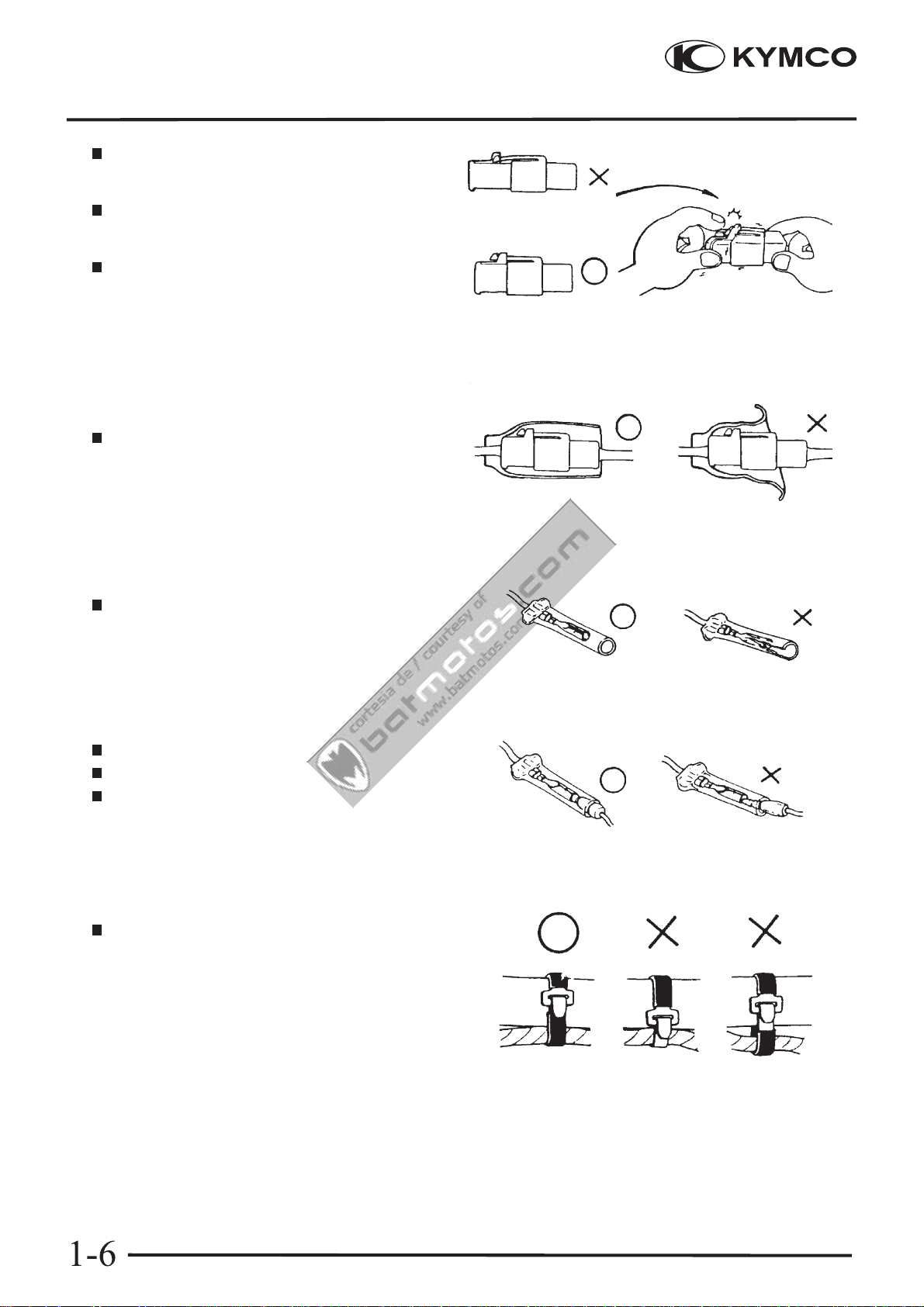
The connector shall be inserted completely.
DOWNTOWN 125i
If the double connector has a lock, lock it
at the correct position.
Check if there is any loose wire.
Before connecting a terminal, check for
damaged terminal cover or loose negative
terminal.
Check the double connector cover for
proper coverage and installation.
click
Insert the terminal completely.
Check the terminal cover for proper coverage.
Do not make the terminal cover opening
face up.
Secure wire harnesses to the frame with
their respective wire bands at the designated
locations.
Tighten the bands so that only the insulated
surfaces contactthe wireharnesses.
-6-
Page 9
1. GENERAL INFORMATION
Cortesia de/ Courtesy of: www.batmotos.com
Cortesia de/ Courtesy of: www.batmotos.com
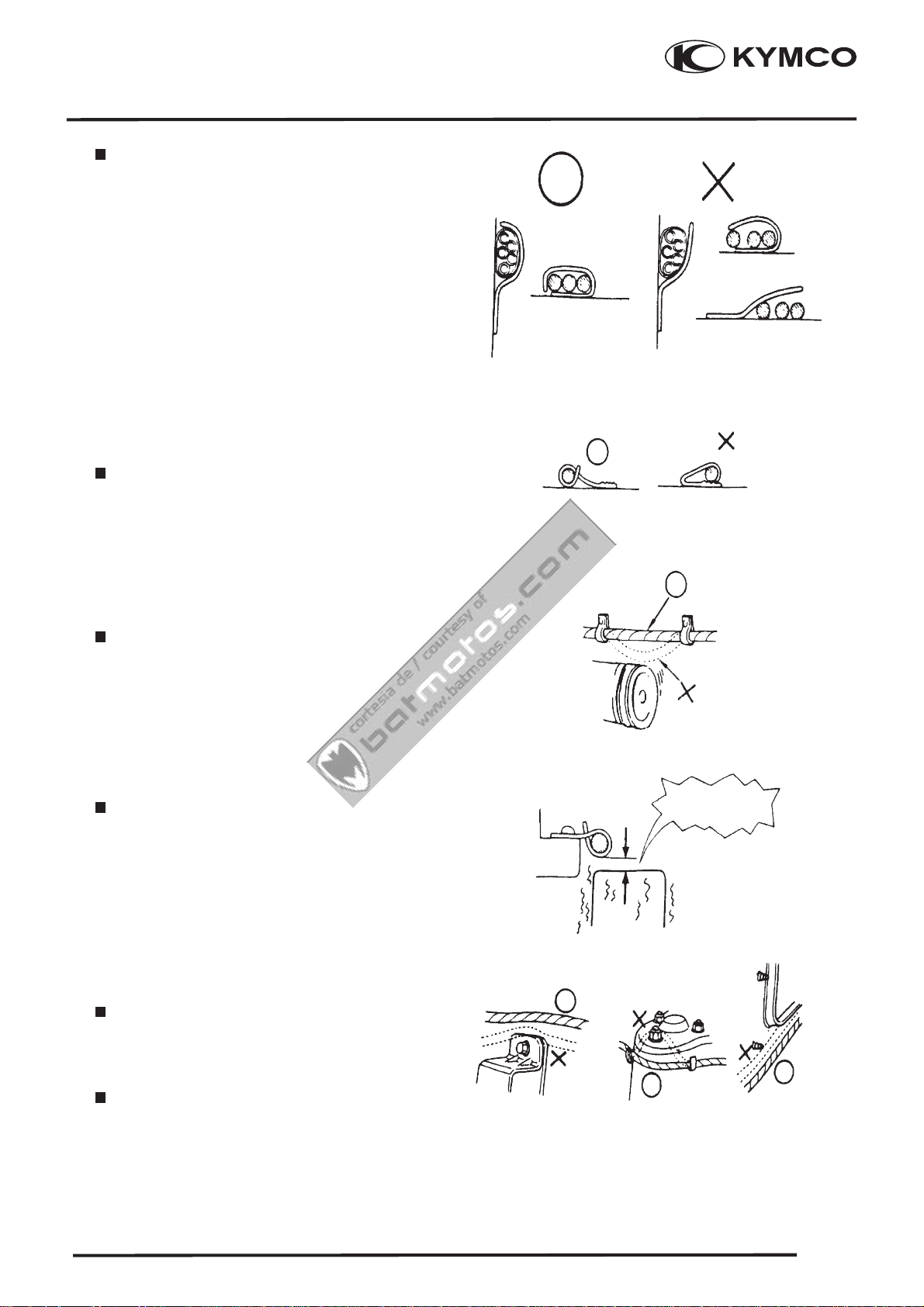
After clamping, check each wire to make
sure it is secure.
Do not squeeze wires against the weld or
its clamp
DOWNTOWN 125i
After clamping, check each harness to make
sure that it is not interfering with any moving
or sliding parts.
When fixing the wire harnesses, do not make
it contact the parts which will generate high
heat.
Route wire harnesses to avoid sharp edges
or corners. Avoid the projected ends of bolts
and screws.
No contact !
Route wire harnesses passing through the side
of bolts and screws. Avoid the projected ends
of bolts and screws.
-7-
1-7
Page 10
1. GENERAL INFORMATION
Cortesia de/ Courtesy of: www.batmotos.com
Cortesia de/ Courtesy of: www.batmotos.com
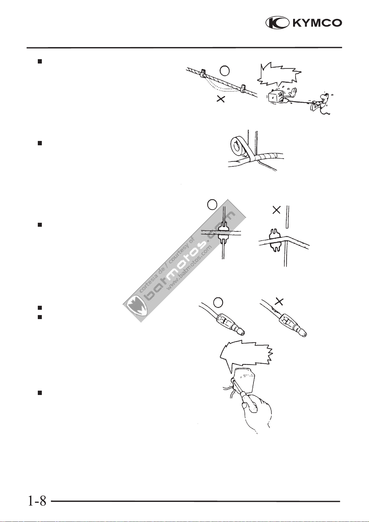
Route harnesses so they are neither pulled
tight nor have excessive slack.
Protect wires and harnesses with electrical
tape or tube if they contact a sharp edge or
corner.
DOWNTOWN 125i
Do not pull
too tight!
When rubber protecting cover is used to
protect the wire harnesses, it shall be
installed securely.
Do not break the sheath of wire.
If a wire or harness is with a broken sheath,
repair by wrapping it with protective tape
or replace it.
When installing other parts, do not press
or squeeze the wires.
Do not press or
squeeze the wire.
-8-
Page 11
1. GENERAL INFORMATION
Cortesia de/ Courtesy of: www.batmotos.com
Cortesia de/ Courtesy of: www.batmotos.com
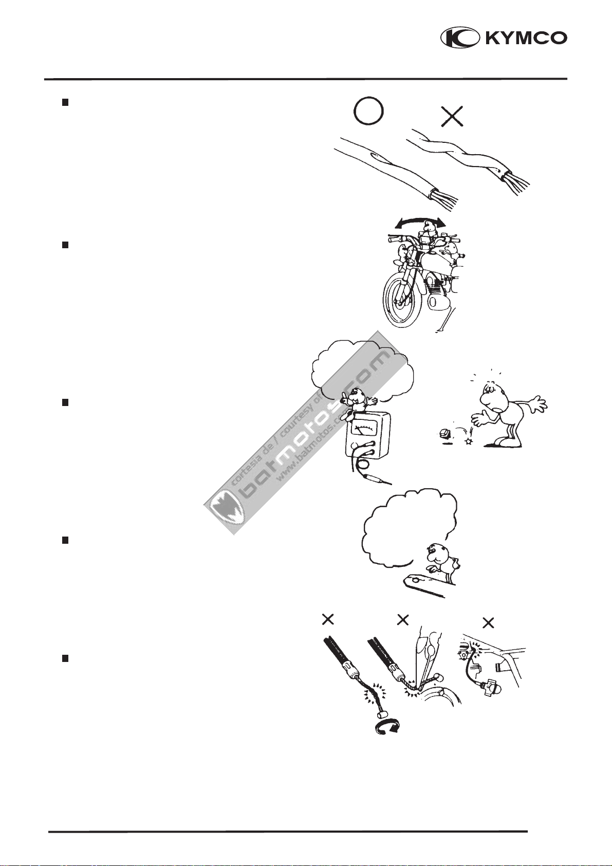
After routing, check that the wire harnesses
are not twisted or kinked.
Wire harnesses routed along with handlebar
should not be pulled tight, have excessive
slack or interfere with adjacent or surrounding
parts in all steering positions.
DOWNTOWN 125i
Do you understand the
instrument?
Is the instrument
set correctly?
When a testing device is used, make sure to
understand the operating methods
thoroughly and operate according
to the operating instructions.
Be careful not to drop any parts.
When rust is found on a terminal, remove
the rust with sand paper or equivalent before
connecting.
Remove Rust !
-9-
1-9
Page 12
1. GENERAL INFORMATION
Cortesia de/ Courtesy of: www.batmotos.com
Cortesia de/ Courtesy of: www.batmotos.com
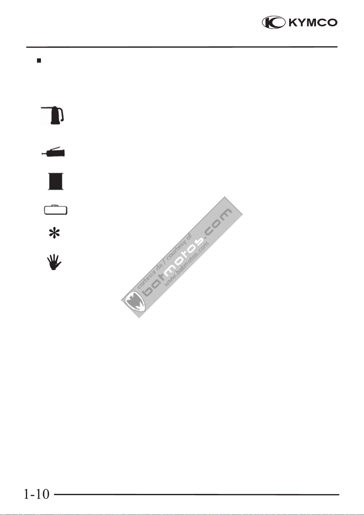
Symbols :
The following symbols represent the servicing methods and cautions included in
this service manual.
DOWNTOWN 125i
Engine Oil
Grease
Gear Oil
Special
:Apply engine oil to the specified points.
(Use designated engine oil for lubrication).
:Apply grease for lubrication.
:Transmission Gear Oil (90#)
:Use special tool.
:Caution
:Warning
.
-10-
Page 13
1. GENERAL INFORMATION
Cortesia de/ Courtesy of: www.batmotos.com
Cortesia de/ Courtesy of: www.batmotos.com
TORQUE VALUES
STANDAR TORQUE VALUES
Item Torque (kg -f m) Item Tor (kg -que f m)
DOWNTOWN 125i
5mm bolt, nut
6mm bolt, nut
8mm bolt, nut
10mm bolt, nut
12mm bolt, nut
Torque specifications listed below are for important fasteners.
ENGINE
Item Qty Thread dia.(mm) Torque (kgf-m) Remarks
Cylinder head bolt A
Cylinder head bolt B
Oil filter screen cap
O2 sensor
Cylinder head cover
Tappet adjusting hole cap
Cam chain set plate
Engine oil drain bolt
Clutch outer nut
Clutch drive plate nut
Starter motor mounting bolt
Oil pump bolt
Drive face nut
Spark plug
A.C. Generator flywheel
Cam chain tensioner pivot
0.45~0.6
0.8~1.2
1.8~2.5
3.0~4.0
5.0~6.0
5mm screw
6mm screw, SH bolt
6mm flange bolt, nut
8mm flange bolt, nut
10mm flange bolt, nut
6
6
30
12
6
30
6
12
12
28
6
6
12
10
12
6
0.45~0.6
0.7~1.1
1.0~1.4
2.4~3.0
3.0~4.5
0.7~1.1
0.7~1.1
2.0~3.0
0.7~1.1
0.8~0.9
1.0~2.0
1.0~1.4
2.0~3.0
5.0~6.0
5.0~6.0
0.8~1.2
0.7~1.1
5.5~6.5
1.0~1.4
5.0~6.0
0.8~1.2
FRAME
Item Qty Thread dia.(mm) Torque (kgf-m) Remarks
Steering stem lock nut
Front axle
Rear axle nut
Rear shock absorber upper bolt
Rear shock absorber lower bolt
Muffler exh. Pipe
-11-
Bc1
14
16
10
10
8
6.0~6.5
1.5~2.5
11~13
3.5~4.5
3.5~4.5
1.8~2.0
U - nut
U - nut
Page 14
1. GENERAL INFORMATION
Cortesia de/ Courtesy of: www.batmotos.com
Cortesia de/ Courtesy of: www.batmotos.com
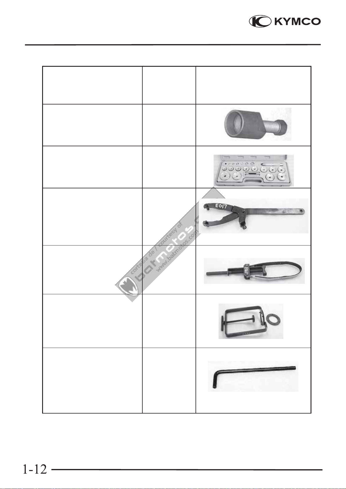
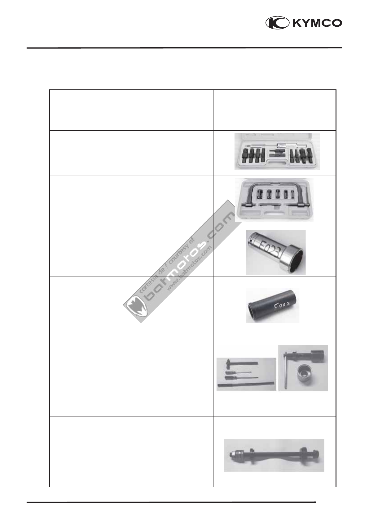
SPECIAL TOOLS
Tool Name Tool No.
Flywheel puller
DOWNTOWN 125i
Illustration
(Note: the special tools may differ
slightly from those shown in the
figure of this manual.)
(Refer to the “STARTER
CLUTCH” section in the chapter
10.)
Oilsealandbearing
installer
Universal holder
(Refer to the “DRIVE PULLEY,
DRIVE BELT AND DRIVEN
PULLEY” section in the chapter
8.)
Flywheel holder
(Refer to the “STARTER
CLUTCH” section in the chapter
10.)
A120E00003
A120E00014
A120E00017
A120E00021
Clutch spring compressor
(Refer to the “DRIVE PULLEY,
DRIVE BELT AND DRIVEN
PULLEY” section in the chapter
8.)
Valve adjuster
(Refer to the “VA LV E
CLEARANCE”sectioninthe
chapter 3.)
A120E00034
A120E00036
(Cont’d)
-12-
Page 15
1. GENERAL INFORMATION
Cortesia de/ Courtesy of: www.batmotos.com
Cortesia de/ Courtesy of: www.batmotos.com
SPECIAL TOOLS
Tool Name Tool No.
Bearing puller A120E00037
Valve spring compressor
DOWNTOWN 125i
Illustration
(Note: the special tools may differ
slightly from those shown in the
figure of this manual.)
(Refer to the “CYLINDER
HEAD” section in the chapter 6.)
Lock nut wrench
(Refer to the “STEERING
STEM” section in the chapter 15.)
Lock nut wrench
(Refer to the “STEERING
STEM” section in the chapter 15.)
Bottom Ball Race
Remove
Cone Race Remove
(Refer to the “STEERING
STEM” section in the chapter 15.)
special tool/ Top Ball
special tool
A120E00040
A120F00023
A120F00002
A120F00009
Bottom Ball Race
Install
Top Ball Cone Race
Install
(Refer to the “STEERING
STEM” section in the chapter 15.)
-13-
special tool
special tool
A120F00019
1-13
Page 16
1. GENERAL INFORMATION
Cortesia de/ Courtesy of: www.batmotos.com
Cortesia de/ Courtesy of: www.batmotos.com
LUBRICATION POINTS
ENGINE
Lubrication Points Lubricant
DOWNTOWN 125i
Valve guide/valve stem movable part
Cam lobes
Valve rocker arm friction surface
Cam chain
Cylinder lock bolt and nut
Piston surroundings and piston ring grooves
Piston pin surroundings
Cylinder inside wall
Connecting rod/piston pin hole
Connecting rod big end
Crankshaft R/L side oil seal
Starter reduction gear engaging part
Countershaft gear engaging part
Final gear engaging part
Bearing movable part
O-ring face
Oil seal lip
Genuine KYMCO Engine Oil (SAE15W-40)
API , SJ Engine Oil
Starter idle gear
Friction spring movable part/shaft movable part
Shaft movable grooved part
A.C. generator connector
Transmission case breather tube
High-temperature resistant grease
Adhesive
1-14
-14-
Page 17

2
Cortesia de/ Courtesy of: www.batmotos.com
Cortesia de/ Courtesy of: www.batmotos.com
. EXHAUST MUFFLER/FRAME COVERS
DOWNTOWN 125i
2
__________________________________________________________________________________
__________________________________________________________________________________
__________________________________________________________________________________
__________________________________________________________________________________
__________________________________________________________________________________
2
EXHAUST MUFFLER/FRAME COVERS
__________________________________________________________________________________
SERVICE INFORMATION------------------------------------------------ 2- 1
TROUBLESHOOTING----------------------------------------------------- 2- 1
FASTENER REMOVAL AND REINSTALLATION------------------ 2- 2
FRAME COVERS REMOVAL/INSTALLATION--------------------- 2- 3
EXHAUST MUFFLER ----------------------------------------------------- 2-14
2-0
Page 18

2
Cortesia de/ Courtesy of: www.batmotos.com
Cortesia de/ Courtesy of: www.batmotos.com
. EXHAUST MUFFLER/FRAME COVERS
DOWNTOWN 125i
SERVICE INFORMATION
GENERAL INSTRUCTIONS
• When removing frame covers, use care not to pull them by force because the cover joint claws
may be damaged.
• Make sure to route cables and harnesses according to the Cable & Harness Routing.
TORQUE VALUES
Exhaust muffler pipe nuts 1.8~2.2 kgf-m
Exhaust muffler brake /RR Frok 3.2~3.8 kgf-m
RR/Engine case 3.0~4.0 kgf-m
TROUBLESHOOTING
Noisy exhaust muffler
• Damaged exhaust muffler
• Exhaust muffler joint air leaks
Lack of power
• Caved exhaust muffler
• Clogged exhaust muffler
• Exhaust muffler air leaks
2-1
Page 19
2
Cortesia de/ Courtesy of: www.batmotos.com
Cortesia de/ Courtesy of: www.batmotos.com
. EXHAUST MUFFLER/FRAME COVERS
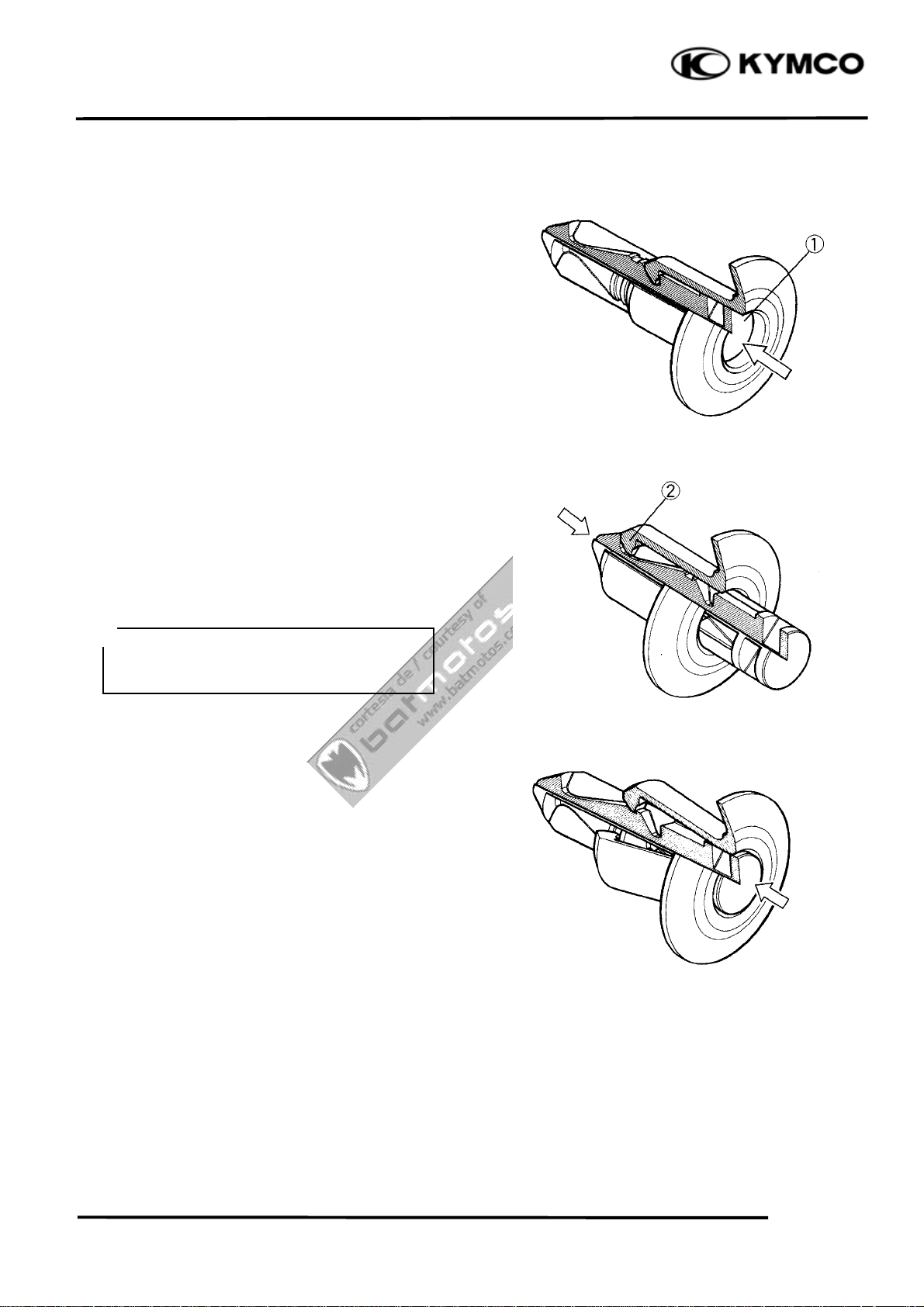
FASTENER REMOVAL AND
REINSTALLATION
REMOVAL
Depress the head of fastener center piece {.
Pull out the fastener.
INSTALLATION
Let the center piece stick out toward the head
so that the pawls | close.
Insert the fastener into the installation hole.
DOWNTOWN 125i
*
To prevent the pawl | from damage,
insert the fastener all the way into the
installation hole
Push in the head of center piece until it
becomes flush with the fastener outside face.
2-2
Page 20
2
r
Cortesia de/ Courtesy of: www.batmotos.com
Cortesia de/ Courtesy of: www.batmotos.com
. EXHAUST MUFFLER/FRAME COVERS
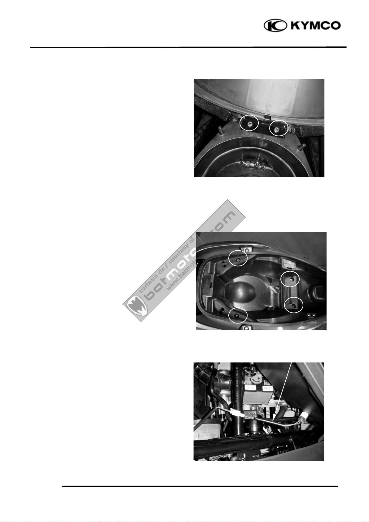
FRAME COVERS REMOVAL/
INSTALLATION
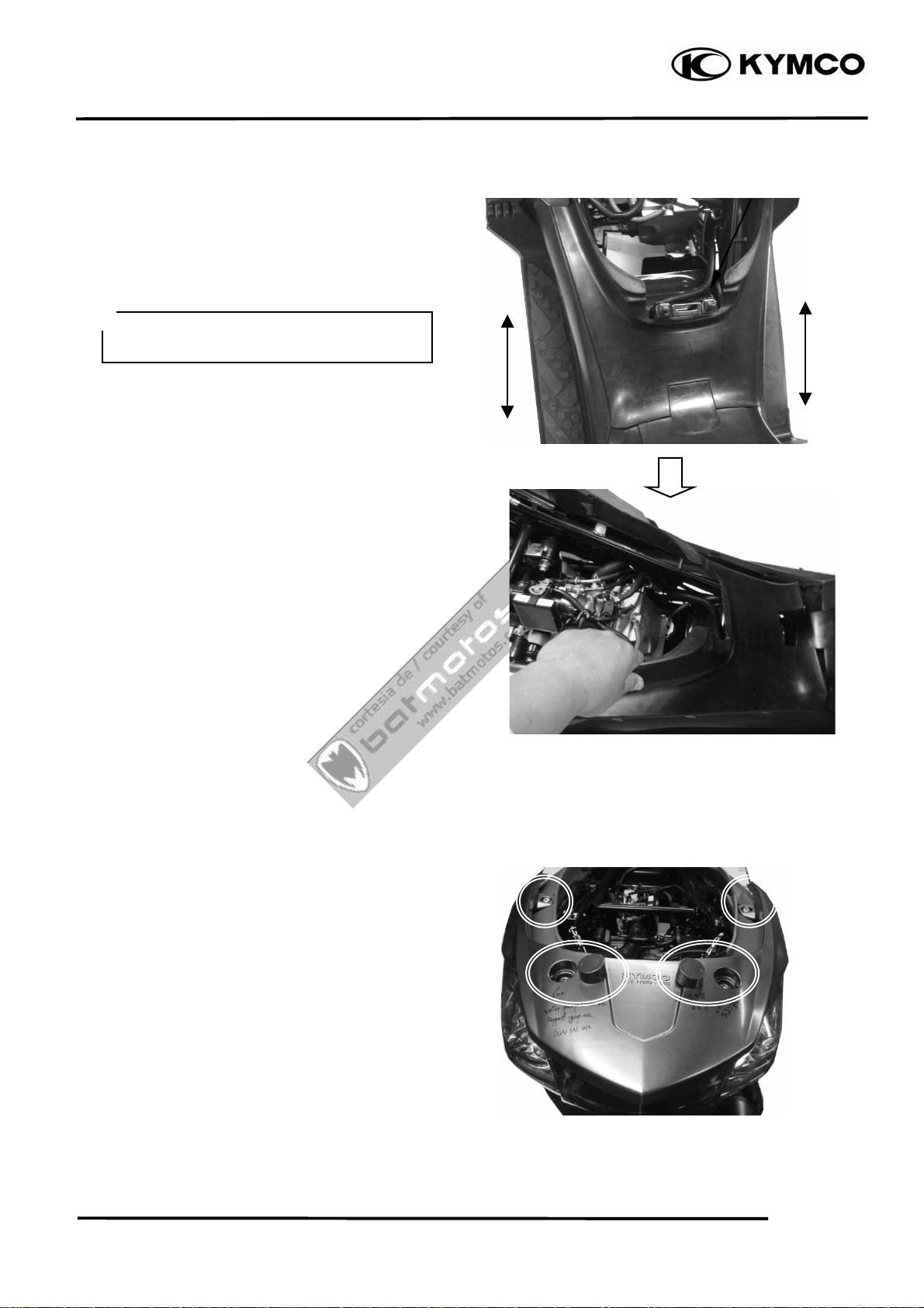
SEAT
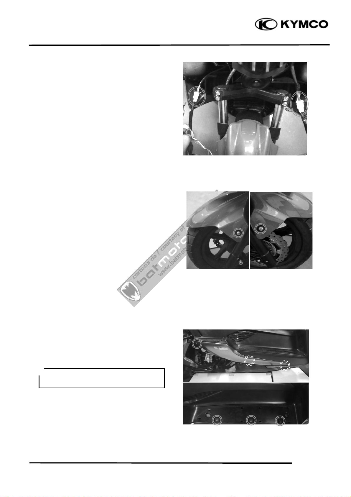
Unlock the seat with the ignition key.
Open the seat.
Remove the two nuts and the seat.
Installation is in the reverse order of removal.
DOWNTOWN 125i
LUGGAGE BOX
Unlock the seat with the ignition key.
Open the seat.
Remove four bolts, and the fastener on the
right side of luggage box, then lift luggage
box.
Disconnect the luggage box light connector,
then remove the luggage box.
Installation is in the reverse order of removal.
Luggage Box Light Connecto
2-3
Page 21
2
r
Cortesia de/ Courtesy of: www.batmotos.com
Cortesia de/ Courtesy of: www.batmotos.com
. EXHAUST MUFFLER/FRAME COVERS
DOWNTOWN 125i
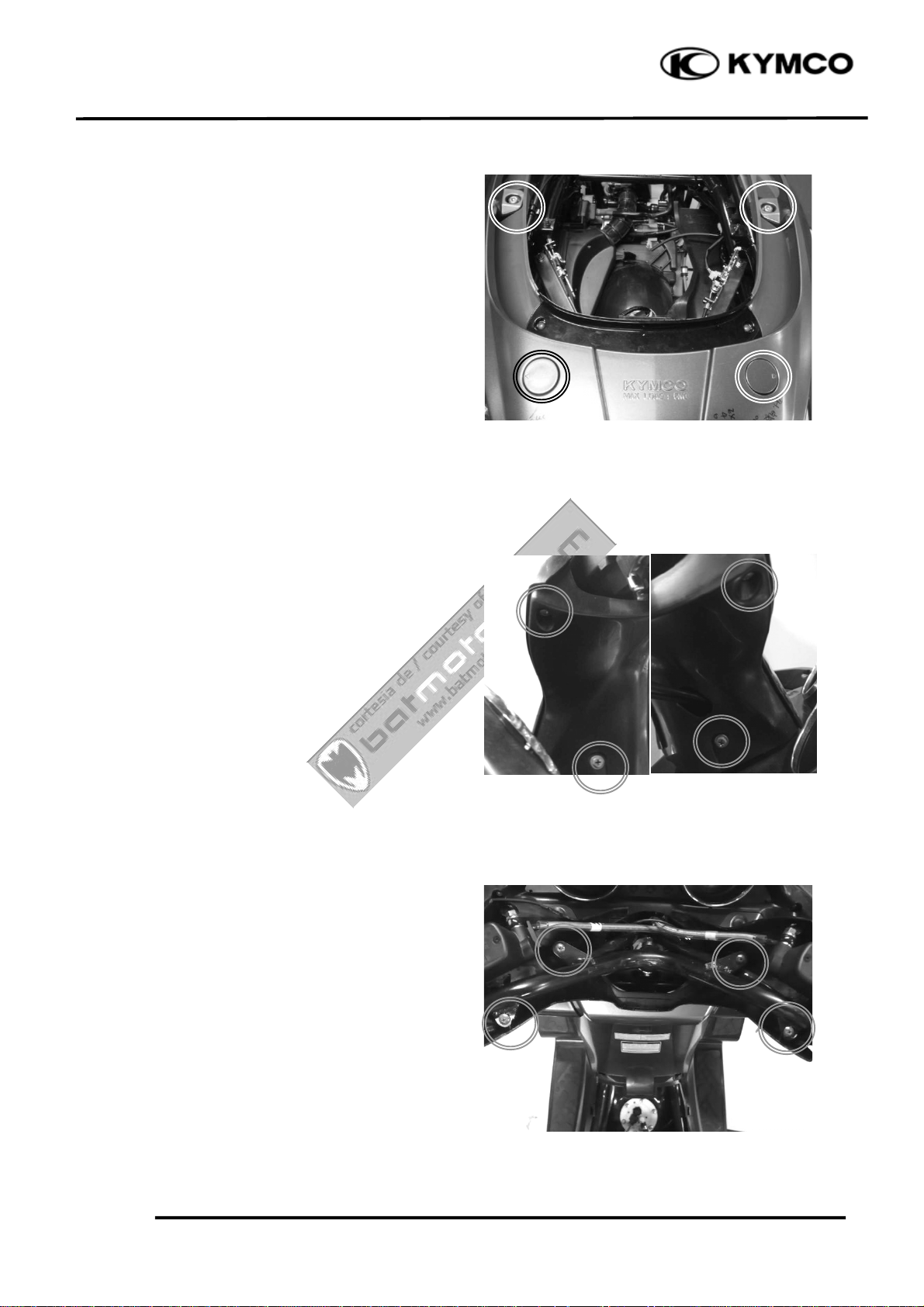
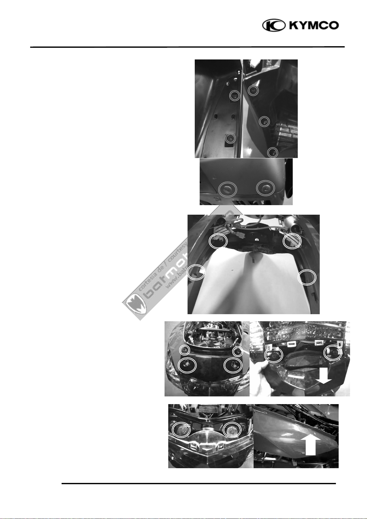
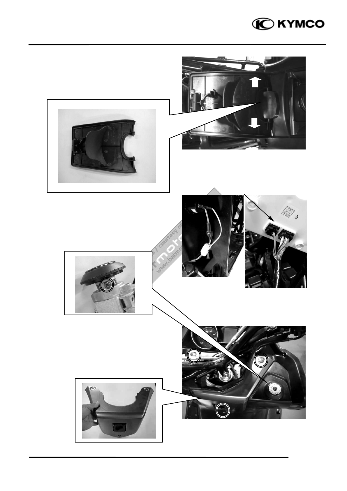
CENTER COVER
Remove the luggage box.
Remove the center cover.
*
During removal, do not pull the joint
claws forcedly to avoid damage.
Installation is in the reverse order of removal.
Center Cove
Remove four bolts and , then remove the rear
carrier.
2-4
Page 22
2
Cortesia de/ Courtesy of: www.batmotos.com
Cortesia de/ Courtesy of: www.batmotos.com
. EXHAUST MUFFLER/FRAME COVERS
Installation is in the reverse order of removal.
DOWNTOWN 125i
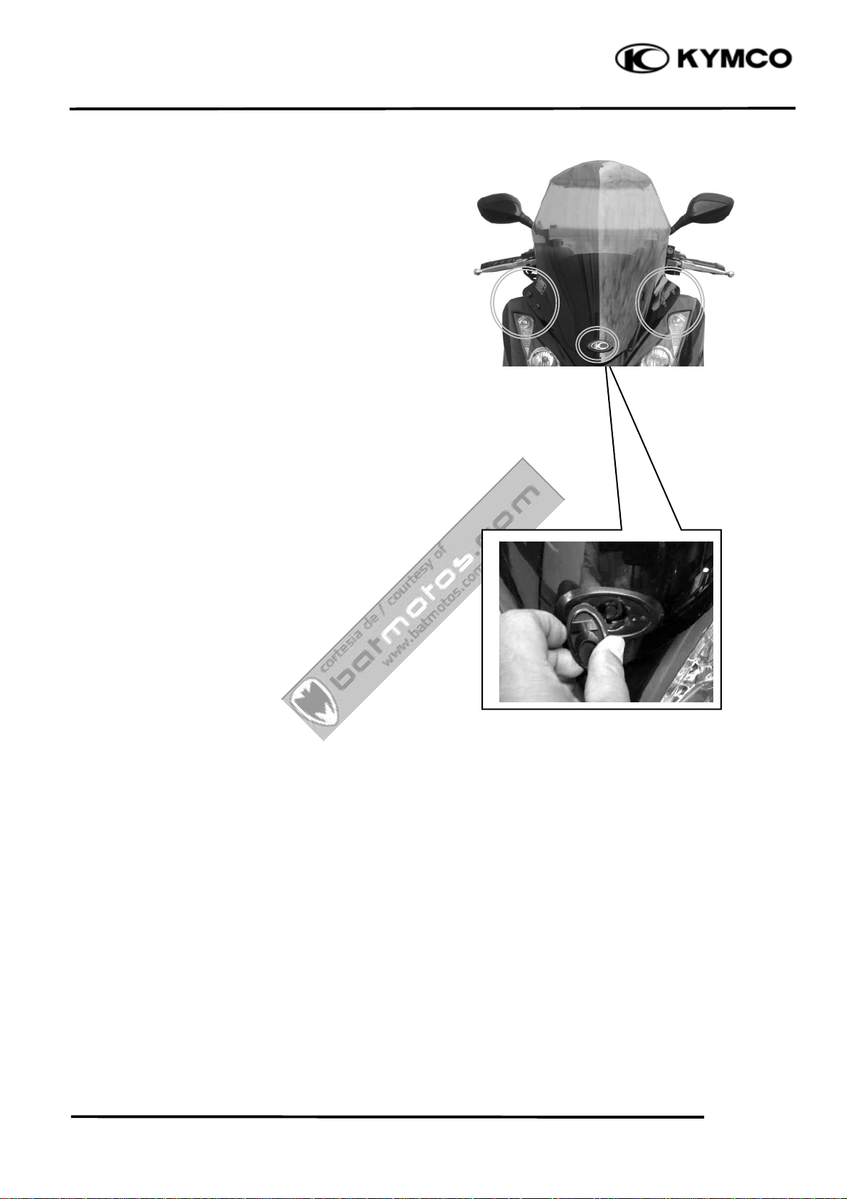
UPPER/LOWER HANDLEBAR COVER
Remove the four screws. then remove upper
handlebar cover.
Remove the four screws, then remove the
bottom handlebar cover.
Disconnect the throttle cable refer to the
“THROTTLE BODY /TPS” section , then
pull the throttle cable out from the lower
cover. Remove the lower cover.
Installation is in the reverse order of removal.
2-5
Page 23
2
Cortesia de/ Courtesy of: www.batmotos.com
Cortesia de/ Courtesy of: www.batmotos.com
. EXHAUST MUFFLER/FRAME COVERS
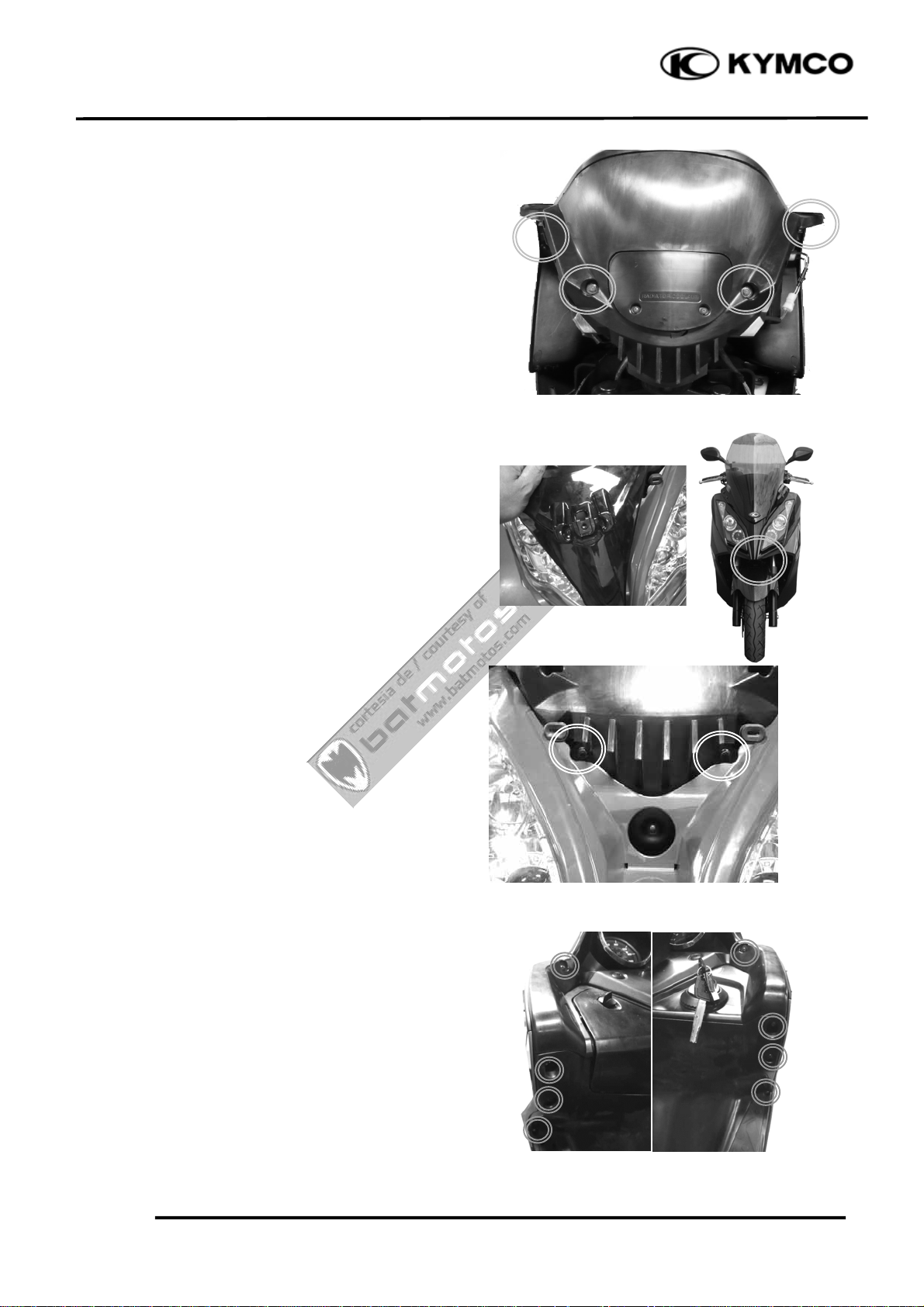
WINDSHIELD/WINDSHIELD GARNISH
Remove five bolts and windshield garnish.
DOWNTOWN 125i
2-6
Page 24
2
Cortesia de/ Courtesy of: www.batmotos.com
Cortesia de/ Courtesy of: www.batmotos.com
. EXHAUST MUFFLER/FRAME COVERS
FRONT CENTER COVER
Remove the windshield
Remove four screws, then remove the front
center cover.
Remove the front cover.
Installation is in the reverse order of removal.
FRONT COVER
Remove the small front cover(black) screw
DOWNTOWN 125i
Remove the small front cover(black)
Remove two nuts.
Remove eight screws from the inner cover.
Remove the front cover
2-7
Page 25
2
Cortesia de/ Courtesy of: www.batmotos.com
Cortesia de/ Courtesy of: www.batmotos.com
. EXHAUST MUFFLER/FRAME COVERS
Disconnect the headlight/position light
connect and right/left turn signal light
connectors.
Installation is in the reverse order of removal.
FRONT FENDER
DOWNTOWN 125i
Remove four screws.
screws and front fender.
Installation is in the reverse order of removal.
RIGHT/LEFT FOOT SKIRT
Remove the six screws attaching to the right
or left skirt.
*
During removal, do not pull the joint
claws forcedly to avoid damage.
Installation is in the reverse order of removal.
2-8
Page 26
2
Cortesia de/ Courtesy of: www.batmotos.com
Cortesia de/ Courtesy of: www.batmotos.com
. EXHAUST MUFFLER/FRAME COVERS
DOWNTOWN 125i
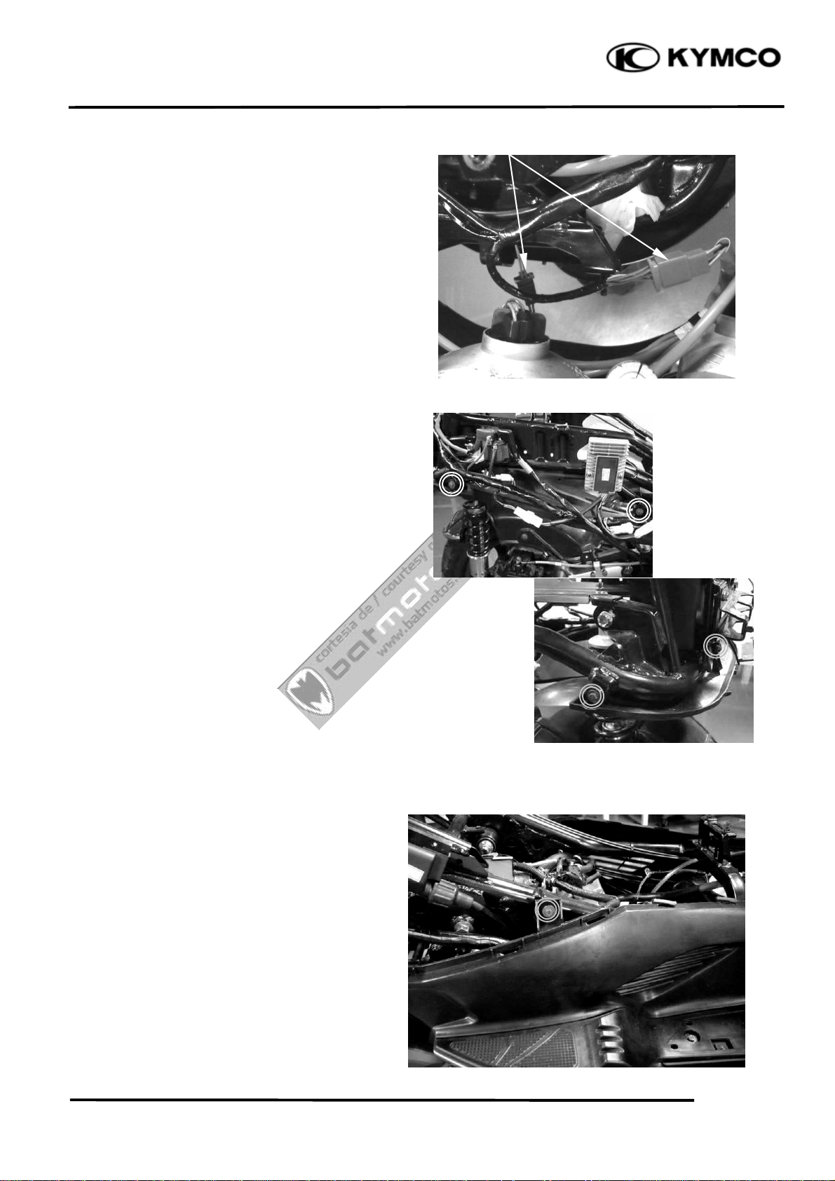
FRONT LOWER COVER
Remove the front cover
Remove the foot skirt
Remove seven screws and front lower cover.
Installation is in the reverse order of removal.
REAR FENDER
Remove the body cover and then the rear
fender .
Installation is in the reverse order of removal.
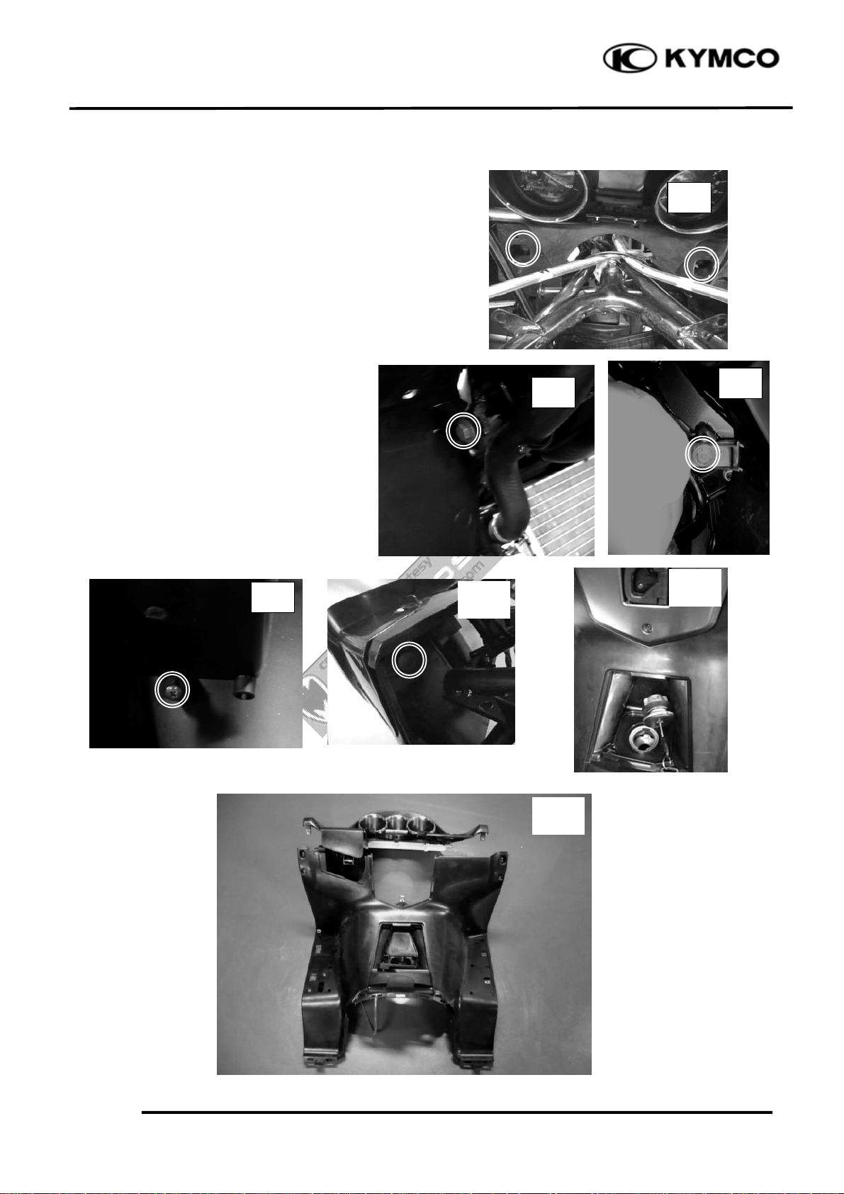
BODY COVER
Remove the rear center cover.
Remove the right and left foot skirts
Remove the rear carrier.
Remove six screws and two nuts then
remove the body cover.
2-9
Page 27
2
r
Cortesia de/ Courtesy of: www.batmotos.com
Cortesia de/ Courtesy of: www.batmotos.com
. EXHAUST MUFFLER/FRAME COVERS
DOWNTOWN 125i
Disconnect the taillight connector.
Installation is in the reverse order of removal.
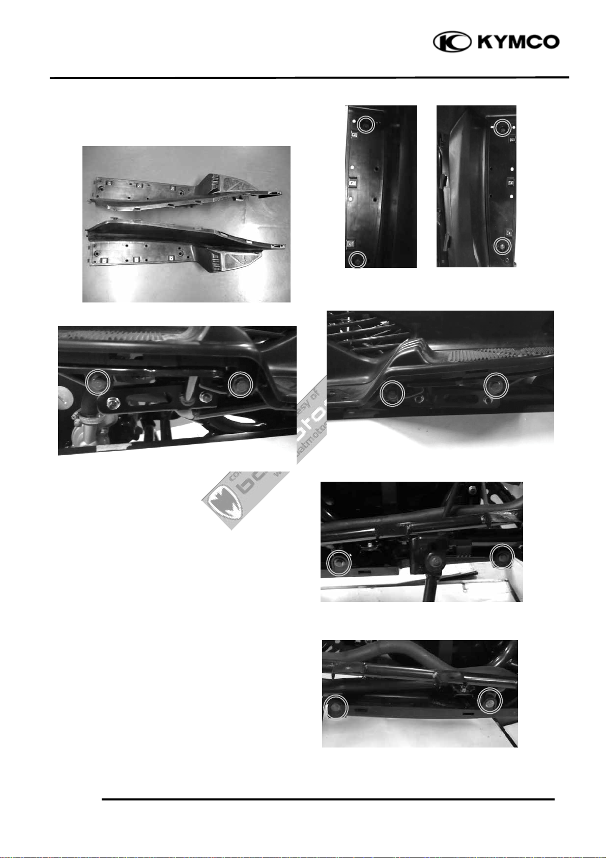
TIRE FENDER
Remove the body cover .
Remove four bolts attaching to the tire fender
Taillight Connecto
Installation is in the reverse order of removal.
FLOORBOARD
Remove the body cover
Remove the right /left skirt
Remove two screws.
2-10
Page 28
2
Cortesia de/ Courtesy of: www.batmotos.com
Cortesia de/ Courtesy of: www.batmotos.com
. EXHAUST MUFFLER/FRAME COVERS
Remove eight bolts, then remove the
floorboard.
DOWNTOWN 125i
UNDER COVER
Remove four bolts
Remove the under cover.
2-11
Page 29
2
Cortesia de/ Courtesy of: www.batmotos.com
Cortesia de/ Courtesy of: www.batmotos.com
. EXHAUST MUFFLER/FRAME COVERS
Remove the fuel tank cap cover.
Installation is in the reverse order of removal.
Speedometer Wires
METER PANEL
DOWNTOWN 125i
Disconnect the speedometer wires.
Disconnect the DC power connectors.
Remove one screws
Remove the ignition key garnish
Remove three screws from the inner cover,
then remove the handler panel.
Installation is in the reverse order of removal.
DC power Connectors
2-12
Page 30
2
Cortesia de/ Courtesy of: www.batmotos.com
Cortesia de/ Courtesy of: www.batmotos.com
. EXHAUST MUFFLER/FRAME COVERS
INNER COVER
Remove the front cover .
Remove the front lower cover .
Remove the floorboard
Remove four bolts and front glove box one
screw.
DOWNTOWN 125i
(1)
Remove two fastener bolts then remove
the fuel tank fill cap.
Remove the inner cover
(3)
(4)
(2)
(2)
(5)
2-13
(6)
Page 31

2
Cortesia de/ Courtesy of: www.batmotos.com
Cortesia de/ Courtesy of: www.batmotos.com
. EXHAUST MUFFLER/FRAME COVERS
EXHAUST MUFFLER
REMOVAL
Disconnect the O2 heater/O2 sensor
connector .
Remove the two exhaust pipe joint nuts
DOWNTOWN 125i
Remove three muffler mount bolts and
muffler and gasket.
2-14
Page 32

2
t
Cortesia de/ Courtesy of: www.batmotos.com
Cortesia de/ Courtesy of: www.batmotos.com
. EXHAUST MUFFLER/FRAME COVERS
INSTALLATION
Replace the gasket with a new one.
Install the exhaust muffler and three
mounting bolt.
Install and tighten the two exhaust pipe joint
nuts to the specified torque
Torque: 20 N•m (2 kgf•m,)
Tighten the three mounting bolts
DOWNTOWN 125i
Torque: 35 N•m (3.5 kgf•m,)
Remove the coolant tank cover.
Gaske
2-15
Page 33

3
Cortesia de/ Courtesy of: www.batmotos.com
Cortesia de/ Courtesy of: www.batmotos.com
. INSPECTION/ADJUSTMENT
DOWNTOWN 125i
3
__________________________________________________________________________________
__________________________________________________________________________________
__________________________________________________________________________________
__________________________________________________________________________________
INSPECTION/ADJUSTMENT
3
__________________________________________________________________________________
SERVICE INFORMATION------------------------------------------------ 3- 1
MAINTENANCE SCHEDULE-------------------------------------------- 3- 2
FUEL LINE------------------------------------------------------------------- 3- 4
THROTTLE OPERATION------------------------------------------------- 3- 4
ENGINE OIL ----------------------------------------------------------------- 3- 5
TRANSMISSION OIL ------------------------------------------------------ 3-11
AIR CLEANER -------------------------------------------------------------- 3-12
SPARK PLUG---------------------------------------------------------------- 3-13
VALVE CLEARANCE ----------------------------------------------------- 3-14
IDLE SPEED ----------------------------------------------------------------- 3-15
CYLINDER COMPRESSION --------------------------------------------- 3-16
DRIVE BELT ---------------------------------------------------------------- 3-16
CLUTCH SHOE WEAR---------------------------------------------------- 3-17
HEADLIGHT AIM ---------------------------------------------------------- 3-17
COOLANT ------------------------------------------------------------------- 3-18
BRAKE FLUID -------------------------------------------------------------- 3-19
BRAKE PAD WEAR ------------------------------------------------------- 3-19
NUTS/BOLTS/FASTENERS ---------------------------------------------- 3-20
WHEELS/TIRES ------------------------------------------------------------ 3-20
SUSPENSION---------------------------------------------------------------- 3-21
SIDE STAND ---------------------------------------------------------------- 3-22
3-0
Page 34

3
g
y
Cortesia de/ Courtesy of: www.batmotos.com
Cortesia de/ Courtesy of: www.batmotos.com
. INSPECTION/ADJUSTMENT
DOWNTOWN 125i
SERVICE INFORMATION
GENERAL
! WARNING
•Before running the engine, make sure that the working area is well-ventilated.
Never run the en
ine in a closed area. The exhaust contains poisonous carbon
monoxide gas which may cause death to people.
•Gasoline is extremel
flammable and is explosive under some conditions. The
working area must be well-ventilated and do not smoke or allow flames or
sparks near the working area or fuel storage area.
SPECIFICATIONS
Throttle grip free play : 2~6 mm
Spark plug : DINK 125: NGK: DPR7EA9
: DOWNTOWN125 i: NGK CR7E
Spark plug gap : 0.6~0.7 mm
Valve clearance : IN: 0.1 mm EX: 0.1 mm
Idle speed : 1850 rpm
Cylinder compression : 15 kg/cm²
Engine oil capacity:
At disassembly : 1.2L
At change : 1.0L
Gear oil capacity :
At disassembly : 0.13L
At change : 0.12L
Coolant capacity :
Reserve tank capacity: 0.49 liter
Radiator capacity : 0.87 liter
Ignition timing : ECU control
TIRE
1 Rider (75 kg) 2 Riders (150 kg)
Front 2.0 kgf/cm² 2.00 kgf/cm²
Rear 2.25 kgf/cm² 2.25 kgf/cm²
TIRE SPECIFICATION:
Front :120/80-14
Rear : 150/70-13
3-1
Page 35

3
Cortesia de/ Courtesy of: www.batmotos.com
Cortesia de/ Courtesy of: www.batmotos.com
. INSPECTION/ADJUSTMENT
TORQUE VALUES
Front axle : 2.0 kgf-m
Rear axle nut : 12 kgf-m
DOWNTOWN 125i
MAINTENANCE SCHEDULE
Perform the pre-ride inspection at each scheduled maintenance period.
This interval should be judged by odometer reading or months, whichever comes first.
I: INSPECT AND CLEAN, ADJUST, LUBRICATE OR REPLACE IF NECESSARY
C: CLEAN R: REPLACE A: ADJUST L: LUBRICATE
The following maintenance schedule specifies all maintenance required to keep your scooter in
peak operating condition. Maintenance work should be performed in accordance with standards
and specifications of KYMCO by properly trained and equipped technicians. Your KYMCO dealer
meets all of these requirements.
*Should be serviced by your KYMCO dealer, unless the owner has the proper tools and service
data and is mechanically qualified.
**In the interest of safety, we recommend these items be serviced only by your KYMCO dealer.
KYMCO recommends that your KYMCO dealer should road test your scooter after each
periodic maintenance is carried out.
3-2
Page 36

3
Cortesia de/ Courtesy of: www.batmotos.com
Cortesia de/ Courtesy of: www.batmotos.com
. INSPECTION/ADJUSTMENT
MAINTENANCE SCHEDULE
DOWNTOWN 125i
FREQUENCY
ITEM MONTH
AIR CLEANER
THROTTLE OPERATION
VALVE CLEARANCE
FUEL LINE
CRANKCASE BREATHER
ENGINE OIL
ENGINE OIL FILTER
ENGINE IDLE SPEED
TRANSMISSION OIL
DRIVE BELT
OIL STRAINER SCREEN
WHICHEVER
COMES
FIRST
X 1000 km
X 1000 mi
ODOMET E R READING
5
1
0.6
1
C
RRRR
10 15 20 25 30
36
I
I
I
I
RRR
RRR
I
912
126
R
I
I
IIII
AAA
I
CCCCCC
CC
RRR
III
I
I
R
R
II
I
15 18
302418
36
RR
RRR
RRRSPARK PLUGS
RI
I
RRRR
I
II
REFER
TO
PAGE
FREQUENCY
ITEM
CLUTCH SHOE WEAR
BRAKE FLUID
BRAKE PAD WEAR
BRAKE SYS T EM
BRAKE LIG HT SW ITCH
STEERING BEARINGS
HEADLIGHT AIM
NUTS, BOLTS, FASTENERS
WHEELS/TIRES
WHICHEVER
COMES
FIRST
X 1000 km
X 1000 mi
NOTE MONTH
ODOMETER READING [NOTE (1)]
5
1
0.6 3 6 9 12 15 18
1
10 15 20 25 30
126
I
I
III
I
R
IIII
II
IIIIII
IIIIII
IIIIII
IIIIII
III
302418
36
II
R
I
R
II
I
III
REFER
TO
PAGE
3-3
Page 37

3
Cortesia de/ Courtesy of: www.batmotos.com
Cortesia de/ Courtesy of: www.batmotos.com
. INSPECTION/ADJUSTMENT
FUEL LINE
Check the fuel lines and replace any parts which
show signs of deterioration, damage or leakage.
THROTTLE OPERATION
DOWNTOWN 125i
Check the throttle grip for smooth movement.
Measure the throttle grip free play.
Free Play: 2~6 mm
Major adjustment of the throttle grip free play is
made with the adjusting nut at the throttle body
side. Adjust by loosening the lock nut and
turning the adjusting nut.
3-4
Page 38

3
S
Cortesia de/ Courtesy of: www.batmotos.com
Cortesia de/ Courtesy of: www.batmotos.com
. INSPECTION/ADJUSTMENT
Minor adjustment is made with the adjusting
nut at the throttle grip side.
Slide the rubber cover (1) out and adjust by
loosening the lock nut (3) and turning the
adjusting nut (2).
(Chart)
ENGINE OIL VIS C OSITIE
20W-40 , 20W-50
20W-40, 20W-50
15W-40 , 15W-50
15W-40, 15W-50
10W-40
10W-40
10W-30
10W-30
20W-40 , 20W-50
5W-50
-10 0 10 20 30 40 C
0 20 40 60 80 100 F
0
0
ENGINE OIL
DOWNTOWN 125i
Engine oil recommendation
Use a premium quality 4-stroke motor oil to
ensure longer service life of your scooter. Use
only oils which are rated, SJ under the API
service classification. The recommended
viscosity is SAE 15W-40. If a SAE 15W-40
motor oil is not available, select an alternative
according to the chart.
Engine oil capacity:
At disassembly:
1.2 L (0.968 lmp qt, 1.166 US qt)
At change:
1.0 L
Engine oil level check
2. Stop the engine and put the scooter on its
center stand on level ground.
3. After a few minutes, remove the oil filler
cap/dipstick, wipe it clean, and reinsert the
oil filler cap/dipstick without screwing it
in. Remove the oil filler cap/dipstick. The
oil level should be between the upper and
lower marks on the oil filler cap/dipstick.
4. If required, add the specified oil up to the
upper level mark. Do not overfill.
5. Reinstall the oil filler cap/dipstick. Check
for oil leaks.
*
Let the engine and exhaust system cool
before working in those areas.
Check the engine oil level each day before
riding the scooter.
The level must be maintained between the
upper and lower level marks on the oil filler
cap/dipstick.
1. Start the engine and let it idle for a few
minutes.
3-5
Page 39

3
Cortesia de/ Courtesy of: www.batmotos.com
Cortesia de/ Courtesy of: www.batmotos.com
. INSPECTION/ADJUSTMENT
Engine oil replacement
Engine oil quality is the chief factor affecting
engine service life. Change the engine oil as
specified in the maintenance schedule.
When running in very dusty conditions, oil
changes should be performed more frequently
than specified in the maintenance schedule.
Please dispose of used engine oil in a manner
that is compatible with the environment. We
suggest you take it in a sealed container to
your local recycling center or service station
for reclamation. Do not throw it in the trash
or pour it on the ground or down a drain.
Used engine oil may cause skin cancer if
repeatedly left in contact with the skin for
prolonged periods. Although this is unlikely
unless you handle used oil on a daily basis, it
is still advisable to thoroughly wash your
hands with soap and water as soon as possible
after handling used oil.
DOWNTOWN 125i
Change the engine oil with the engine at
normal operating temperature and the scooter
on its center stand to assure complete and
rapid draining.
3-6
Page 40

3
Cortesia de/ Courtesy of: www.batmotos.com
Cortesia de/ Courtesy of: www.batmotos.com
. INSPECTION/ADJUSTMENT
1. Remove the oil filler cap/dipstick(1)
from the right crankcase cover.
2. Place a container under the left crankcase.
3. Remove the oil drain plug (2) to drain the
oil.
4. Reinstall the drain plug and tighten the
drain plug to specification.
Oil drain plug torque:
25 N-m (2.5 kgf-m,)
5. Fill the crankcase with the recommended
grade oil and install the oil filler cap.
Oil capacity (after draining):
1.0 L(0.95 US qt, 0.8 lmp qt)
6. Start the engine and let it idle for 2-3
minutes.
7. Stop the engine and check that the oil level
is at the upper level mark on the oil filler
cap/dipstick with the scooter upright on
firm, level ground. Make sure there are no
oil leaks.
DOWNTOWN 125i
(1)
*
Let the engine and exhaust system cool
before working in those areas.
(2)
3-7
Page 41

3
Cortesia de/ Courtesy of: www.batmotos.com
Cortesia de/ Courtesy of: www.batmotos.com
. INSPECTION/ADJUSTMENT
Oil strainer screen clean
Change the engine oil with the engine at
normal operating temperature and the scooter
on its center stand to assure complete and
rapid draining.
*
Let the engine and exhaust system cool
before working in those areas.
1. Remove the oil filler cap/dipstick (1) from
the right crankcase cover.
2. Place a drain pan under the crankcase and
remove the oil strainer screen cap (2).
The spring (3) and oil strainer screen (4)
will come out when the drain plug is
removed.
Let the engine oil drain out.
3. Clean the oil strainer screen.
4. Check that the oil strainer screen, sealing
rubber and drain plug O-ring are in good
condition.
5. Install the oil strainer screen, spring and oil
strainer screen cap.
DOWNTOWN 125i
(1)
Oil strainer screen cap torque:
15N-m (1.5 kgf-m)
6. Fill the crankcase with the recommended
grade oil and install the oil strainer screen
cap.
Oil capacity (after draining):
1.0 L
7. Start the engine and let it idle for 2-3
minutes.
8. Stop the engine and check that the oil level
is at the upper level mark on the oil filler
cap/dipstick with the scooter upright on
firm, level ground. Make sure there are no
oil leaks.
3-8
Page 42

3
Cortesia de/ Courtesy of: www.batmotos.com
Cortesia de/ Courtesy of: www.batmotos.com
. INSPECTION/ADJUSTMENT
Oil filter replacement
Change the engine oil with the engine at
normal operating temperature and the scooter
on its center stand to assure complete and
rapid draining.
*
Let the engine and exhaust system cool
before working in those areas.
1. Remove the oil filler cap/dipstick (1) from
the right crankcase cover.
2. Place a drain pan under the crankcase.
Remove three bolts and then remove the
oil filter cap (2) and O-ring (3).
The spring (4) will come out when the
filter cap is removed.
Let the engine oil drain out.
DOWNTOWN 125i
(1)
3. Remove and discard the oil filter (5).
*
Do not remain the rubber seal on the oil
filter in the oil filter housing.
4. Check that the O-ring is in good condition.
(2)
3-9
Page 43

3
r
Cortesia de/ Courtesy of: www.batmotos.com
Cortesia de/ Courtesy of: www.batmotos.com
. INSPECTION/ADJUSTMENT
5. Install the new oil filter.
*
Make sure the rubber seal on the oil filte
facing the left crankcase.
6. Install the spring, O-ring and cap.
Torque:
12 N-m (1.2 kgf-m)
DOWNTOWN 125i
Rubber Seal
7. Fill the crankcase with the recommended
grade oil and install the oil filler cap.
Oil capacity (after draining):
1.0 L
8. Start the engine and let it idle for 2-3
minutes.
9. Stop the engine and check that the oil level
is at the upper level mark on the oil filler
cap/dipstick with the scooter upright on
firm, level ground. Make sure there are no
oil leaks.
3-10
Page 44

3
Cortesia de/ Courtesy of: www.batmotos.com
Cortesia de/ Courtesy of: www.batmotos.com
. INSPECTION/ADJUSTMENT
TRANSMISSION OIL
Oil change
1. Place the scooter in its center stand.
2. Place a drain pan under the drain bolt (1).
3. Remove the transmission oil drain bolt.
4. Remove the transmission oil filler bolt (2),
slowly turn the rear wheel and drain the
oil.
After draining the oil completely, install
the oil drain bolt with a new sealing
washer and tighten it.
Torque: 13 N-m (1.3 kgf-m)
DOWNTOWN 125i
(1)
5. Fill the transmission case with
recommended oil.
Recommended transmission oil: SAE 90
Oil capacity (at draining):
0.12 L
6. Install the transmission oil filler bolt with a
new sealing washer and tighten it.
Torque: 13 N-m (1.3 kgf-m)
(2)
3-11
Page 45

3
Cortesia de/ Courtesy of: www.batmotos.com
Cortesia de/ Courtesy of: www.batmotos.com
. INSPECTION/ADJUSTMENT
AIR CLEANER
The air cleaner should be serviced at regular
intervals. Service more frequently when
riding in unusually wet or dusty areas.
Air cleaner element replacement
1. Remove the screws from the air cleaner
cover , then remove air cleaner cover.
2. Remove screws from the air cleaner
element , then remove and discard this air
cleaner element.
4. The new air cleaner element installation is
in the reverse order of removal.
DOWNTOWN 125i
Use the KYMCO genuine air cleaner element
or an equivalent air cleaner element specified
for your model. Using the wrong KYMCO air
cleaner element or a non-KYMCO air cleaner
element which is not of equivalent quality
may cause premature engine wear or
performance problems.
1. Remove the band (1).
3-12
Page 46

3
k
Cortesia de/ Courtesy of: www.batmotos.com
Cortesia de/ Courtesy of: www.batmotos.com
. INSPECTION/ADJUSTMENT
SPARK PLUG
Remove the spark plug cap and spark plug
Check the spark plug for wear and fouling
deposits.
Clean any fouling deposits with a spark plug
cleaner or a wire brush.
Specified Spark Plug:
NGK CR7E
Measure the spark plug gap.
Spark Plug Gap: 0.6~0.7 mm
DOWNTOWN 125i
Cracks
Damage
Deformation
*
When installing, first screw in the spar
plug by hand and then tighten it with a
spark plug wrench.
Torque: 0.9 kgf-m (9 N-m)
Gap
Wear
Fouling
Deposits
}
0.6~0.7mm
3-13
Page 47

3
Cortesia de/ Courtesy of: www.batmotos.com
Cortesia de/ Courtesy of: www.batmotos.com
. INSPECTION/ADJUSTMENT
VALVE CLEARANCE
*
• Inspect and adjust valve clearance
while the engine is cold (below 35℃).
Remove the four bolts , then remove cylinder
head cover.
Remove the timing hole cap and O-ring
Remove the crankshaft hole cap and O-ring .
DOWNTOWN 125i
Timing hole cap
Turn the A.C. generator flywheel to the top
dead center (TDC) on the compression stroke
so that the “T” mark on the flywheel aligns
with the index mark on the left crankcase
cover.
The punch mark on the camshaft should face
upward as shown.
If the punch mark on the camshaft are facing
downward, turn the crankshaft one full turn
(180°) and the punch mark are facing upward.
Crankshaft hole cap
Punch Mark
3-14
Page 48

3
Cortesia de/ Courtesy of: www.batmotos.com
Cortesia de/ Courtesy of: www.batmotos.com
. INSPECTION/ADJUSTMENT
Adjust by loosening the valve adjusting screw
lock-nut and turning the adjusting screw
until there is a slight drag on the thickness
gauge .
Valve Clearance: IN: 0.1 mm
EX:0.1 mm
Apply oil to the valve adjusting screw locknut threads and seating surface.
Hold the adjusting screw and tighten the lock
nut to the specified torque.
Torque: 0.9 kgf-m (9 N-m)
Special tool:
Valve adjuster A120E00036
DOWNTOWN 125i
After tightening the lock-nut, recheck the
valve clearance.
Install the removed parts in the reverse order
of removal.
IDLE SPEED
*
● It is not necessary to adjust idle speed
for DOWNTOWN125i. The throttle
body is factory preset originally, do not
loosen or tighten the painted bolts and
screws of throttle body. Loosening or
tightening them can cause throttle a idle
and valve with failure.
Warm up the engine before this operation.
Start the engine and connect a tachometer.
Turn the throttle stop screw (1) to obtain the
specified idle speed.
Idle Speed:
DINK 125: 1700 rpm
DOWNTOWN125i: 1850 rpm
When the engine misses or run erratic, adjust
the pilot screw (2).
3-15
Page 49

3
Cortesia de/ Courtesy of: www.batmotos.com
Cortesia de/ Courtesy of: www.batmotos.com
. INSPECTION/ADJUSTMENT
CYLINDER COMPRESSION
Warm up the engine before compression test.
Remove the center cover and spark plug cap.
Remove the spark plug .
Insert a compression gauge.
Open the throttle valve fully and push the
starter button to test the compression.
Compression:
Downtown125i:15 kg/cm²
If the compression is low, check for the
following:
‧Leaky valves
‧Valve clearance too small
‧Leaking cylinder head gasket
‧Worn pistons
‧Worn piston/cylinder
If the compression is high, it indicates that
carbon deposits have accumulated on the
combustion chamber and the piston head.
DOWNTOWN 125i
DRIVE BELT
Remove the left crankcase cover.
Inspect the drive belt
for cracks or excessive wear.
Replace the drive belt with a new
one if necessary and in accordance
with the Maintenance Schedule.
3-16
Page 50

3
Cortesia de/ Courtesy of: www.batmotos.com
Cortesia de/ Courtesy of: www.batmotos.com
. INSPECTION/ADJUSTMENT
CLUTCH SHOE WEAR
Start the engine and check the clutch
operation by increasing the engine speed
gradually.
If the scooter tends to creep, or the engine
stalls, check the clutch shoes for wear and
replace if necessary (refer to the “DRIVE
PULLEY, DRIVE BELT AND DRIVEN
PULLEY” section in the chapter 8).
DOWNTOWN 125i
HEADLIGHT AIM
Remove the front cover
Place the scooter on a level surface
Adjust the headlight beam adjuster.
A clockwise rotation moves the beam up
and counterclockwise rotation moves the
beam down.
Adjust the headlight beam horizontally by
turning the horizontal beam adjuster.
A clockwise rotation moves the beam toward
the right side of the rider.
Horizontally Adjusting Screw
Vertically Adjusting Screw
3-17
Page 51

3
Cortesia de/ Courtesy of: www.batmotos.com
Cortesia de/ Courtesy of: www.batmotos.com
. INSPECTION/ADJUSTMENT
COOLANT
Inspection
The reserve tank is under left foot board.
Check the coolant level through the
inspection window (1) at the front lower
cover while the engine is at the normal
operating temperature with the scooter in an
upright position. If the coolant level is below
the LOWER level mark (3), remove screw (4)
and reserve tank lid (5) and reserve tank cap
(6) and add coolant mixture until it reaches
the upper level mark (2).
Always add coolant to the reserve tank. Do
not attempt to add coolant by removing the
radiator cap.
If the reserve tank is empty, or if coolant loss
is excessive, check for leaks and see your
KYMCO dealer for repair.
DOWNTOWN 125i
3-18
Page 52

3
Cortesia de/ Courtesy of: www.batmotos.com
Cortesia de/ Courtesy of: www.batmotos.com
. INSPECTION/ADJUSTMENT
BRAKE FLUID
Brake fluid level
With the scooter in an upright position, check
the front and rear fluid level. It should be
above the lower level mark. If the level is at
or below the lower level mark "L", check the
brake pads for wear.
Worn pads should be replaced. If the pads are
not worn, have your brake system inspected
for leaks.
The recommended brake fluid is DOT 4
brake fluid from a sealed container, or an
equivalent.
Other checks
Make sure there are no fluid leaks. Check for
deterioration or cracks in the hoses and
fittings.
DOWNTOWN 125i
Front brake
BRAKE PAD WEAR
Brake pad wear depends upon the severity of
usage, the type of riding, and road conditions.
(Generally, the pads will wear faster on wet
and dirty roads.) Inspect the pads at each
regular maintenance interval.
Front brake /Rear brake
Check the cutout in each pad.
If either pad is worn to the cutout, replace
both pads as a set. See your KYMCO dealer
for this service.
Rear brake
3-19
Page 53

3
Cortesia de/ Courtesy of: www.batmotos.com
Cortesia de/ Courtesy of: www.batmotos.com
. INSPECTION/ADJUSTMENT
NUTS/BOLTS/FASTENERS
Check all important chassis nuts and bolts for
looseness.
Tighten them to their specified torque values
if any looseness is found.
WHEELS/TIRES
Tire pressure
Insufficient air pressure in the tires not only
hastens tire wear but also seriously affects the
stability of the scooter. Under inflated tires
make smooth cornering difficult and
overinflated tires decrease the amount of tire
in contact with the ground which can lead to
skids and loss of control. Be sure that the tire
pressure is within the specified limits at all
times. Tire pressure should only be adjusted
when the tires are cold.
DOWNTOWN 125i
Cold inflation tire pressure
1 Rider (75 kg) 2 Riders (150 kg)
2.0kg/cm² 2.25 kg/cm²
Front
2.0kg/cm² 2.25 kg/cm²
Rear
3-20
Page 54

3
Cortesia de/ Courtesy of: www.batmotos.com
Cortesia de/ Courtesy of: www.batmotos.com
. INSPECTION/ADJUSTMENT
SUSPENSION
Check the action of the front/rear shock
absorbers by compressing them several times.
Check the entire shock absorber assembly for
oil leaks, looseness or damage.
Jack the rear wheel off the ground and move
the rear wheel sideways with force to see if
the engine hanger bushings are worn.
Replace the engine hanger bushings if there is
any looseness.
DOWNTOWN 125i
Rear suspension adjustment
3-21
Page 55

3
Cortesia de/ Courtesy of: www.batmotos.com
Cortesia de/ Courtesy of: www.batmotos.com
. INSPECTION/ADJUSTMENT
SIDE STAND
Perform the following maintenance in
accordance with the maintenance schedule.
Functional check
Check the spring for damage or loss of
tension and the side stand assembly for
freedom of movement.
Check the side stand ignition cut-off system:
DOWNTOWN 125i
1. Place the scooter on its center stand.
2. Put the side stand up and start the engine.
3. Lower the side stand. The engine should
stop as you put the side stand down.
If the side stand system does not operate as
described, see your KYMCO dealer for
service.
Side stand up
Side stand down
3-22
Page 56

4
Cortesia de/ Courtesy of: www.batmotos.com
Cortesia de/ Courtesy of: www.batmotos.com
. LUBRICATION SYSTEM
DOWNTOWN 125i
4
__________________________________________________________________________________
__________________________________________________________________________________
__________________________________________________________________________________
__________________________________________________________________________________
__________________________________________________________________________________
4
LUBRICATION SYSTEM
__________________________________________________________________________________
LUBRICATION SYSTEM DIAGRAM---------------------------------- 4-1
SERVICE INFORMATION------------------------------------------------ 4-2
TROUBLESHOOTING----------------------------------------------------- 4-2
OIL PUMP ------------------------------------------------------------------- 4-3
4-0
Page 57

4
r
Cortesia de/ Courtesy of: www.batmotos.com
Cortesia de/ Courtesy of: www.batmotos.com
. LUBRICATION SYSTEM
LUBRICATION SYSTEM DIAGRAM
Rocker Arm Shaft
DOWNTOWN 125i
4-1
Crankshaft
Oil Straine
Screen
Oil Pump
Oil Filter Screen
Page 58

4
Cortesia de/ Courtesy of: www.batmotos.com
Cortesia de/ Courtesy of: www.batmotos.com
. LUBRICATION SYSTEM
DOWNTOWN 125i
SERVICE INFORMATION
GENERAL INSTRUCTIONS
• The maintenance of lubrication system can be performed with the engine installed in the frame.
• Drain the coolant before starting any operations.
• Be careful when removing and installing the oil pump not to allow dust and foreign matters to
enter the engine and oil line.
• Do not attempt to disassemble the oil pump. The oil pump must be replaced as a set when it
reaches its service limit.
• After the oil pump is installed, check each part for oil leaks.
SPECIFICATIONS Unit: mm
Standard
Inner rotor-to-outer rotor clearance 0.15
Outer rotor-to-pump body clearance 0.15~0.2
Rotor end-to-pump body clearance 0.04~0.09
ENGINE OIL
Engine Oil Capacity
Recommended Oil SAE15W40 API: SJ
At disassembly: 1.2 liter
At change: 1.0 liter
TROUBLESHOOTING
Oil level too low Poor lubrication pressure
• Natural oil consumption • Oil level too low
• Oil leaks • Clogged oil filter or oil passage
• Worn piston rings • Faulty oil pump
• Worn valve guide
• Worn valve guide seal
Oil contamination
• Oil not changed often enough
• Faulty cylinder head gasket
• Loose cylinder head bolts
4-2
Page 59

4
r
t
r
Cortesia de/ Courtesy of: www.batmotos.com
Cortesia de/ Courtesy of: www.batmotos.com
. LUBRICATION SYSTEM
OIL PUMP
DOWNTOWN 125i
REMOVAL
Remove the flywheel and driven gear (refer
to the “STARTER CLUTCH” section in the
chapter 10).
Remove the bolt and then oil separator cover.
*
When removing and installing the oil
pump, be careful not to allow dust or dirt
to enter the engine.
Pry the snap ring off and remove the oil pump
driven gear, then remove the oil pump drive
chain.
Bolts
Oil Separator Cove
Remove the two oil separator bolts to remove
the oil pump.
4-3
Snap Ring
Oil Separator Bol
Oil Pump Driven Gea
Oil Pump
Page 60

4
p
r
r
t
r
Cortesia de/ Courtesy of: www.batmotos.com
Cortesia de/ Courtesy of: www.batmotos.com
. LUBRICATION SYSTEM
DOWNTOWN 125i
INSTALLATION
Install the oil pump and oil separator and
tighten the two bolts.
The arrow mark must be keep upward.
*
Make sure the pump shaft rotates freely
and arrow on the oil pump is upside.
Install the pump drive chain and driven gear,
then set the snap ring securely on the pump
shaft.
Arrow Mark
Oil Separato
Pump Drive Chain Snap Ring
Bolts
Snap Ring
Install the oil separator cover properly.
*
Fit the tab of the separator cover into the
slit in the separator.
Pump Driven Gea
Oil Se
arator Cove
Bol
4-4
Page 61

4
r
r
r
t
r
r
t
Cortesia de/ Courtesy of: www.batmotos.com
Cortesia de/ Courtesy of: www.batmotos.com
. LUBRICATION SYSTEM
DISASSEMBLY
Remove the screw and disassemble the oil
pump as shown.
Pump Cove
DOWNTOWN 125i
Outer Roto
Screw
ASSEMBLY
Inner Roto
Pump Body
Dowel Pin
Pump Shaf
Install the outer rotor, inner rotor and pump
shaft into the pump body.
*
Insert the pump shaft by aligning the flat
on the shaft with the flat in the inner
rotor. Install the dowel pin.
There is one punch mark on the surface of the
inner rotor and outer rotor.
The mark is upside.
4-5
Dowel Pin
Outer Roto
Inner Roto
Pump Body
Pump Shaf
Page 62

5
Cortesia de/ Courtesy of: www.batmotos.com
Cortesia de/ Courtesy of: www.batmotos.com
. ENGINE REMOVAL/INSTALLATION
DOWNTOWN 125i
5
__________________________________________________________________________________
__________________________________________________________________________________
__________________________________________________________________________________
__________________________________________________________________________________
__________________________________________________________________________________
5
ENGINE REMOVAL/INSTALLATION
__________________________________________________________________________________
SERVICE INFORMATION------------------------------------------------ 5-1
ENGINE REMOVAL/INSTALLATION--------------------------------- 5-2
ENGINE HANGER --------------------------------------------------------- 5-8
5-0
Page 63

5. ENGINE REMOVAL/INSTALLATION
Cortesia de/ Courtesy of: www.batmotos.com
Cortesia de/ Courtesy of: www.batmotos.com
DOWNTOWN 125i
SERVICE INFORMATION
GENERAL INSTRUCTIONS
• A floor jack or other adjustable support is required to support and maneuver the engine. Be
careful not to damage the scooter body, cables and wires during engine removal.
• Use shop towels to protect the scooter body during engine removal.
• Drain the coolant before removing the engine.
• After the engine is installed, fill the cooling system with coolant and be sure to bleed air from the
water jacket. Start the engine to check for coolant leaks.
• Before removing the engine, the rear brake caliper must be removed first. Be careful not to bend
or twist the brake fluid tube.
SPECIFICATIONS
Engine oil capacity: at disassembly: 1.2 L ( 1.27 US qt)
: at change: 1.0 L ( 1.06 US qt)
Coolant capacity:
Radiator capacity : 0.87 liter
Reserve tank capacity : 0.49 liter
TORQUE VALUES
Engine hanger (Engine side) 5 kgf-m (50 N-m)
Engine hanger (Frame side) 6.5 kgf-m (65 N-m)
5-1
Page 64

5
Cortesia de/ Courtesy of: www.batmotos.com
Cortesia de/ Courtesy of: www.batmotos.com
. ENGINE REMOVAL/INSTALLATION
ENGINE
REMOVAL/INSTALLATION
REMOVAL
Remove the air cleaner
Disconnect the ECU connector (A)
Disconnect the O2 heater/O2 sensor
connector
Disconnect the throttle cable(B)
DOWNTOWN 125i
(A)
*
Remove a bolt from fuel hose guide (C).
Disconnect the fuel hose (D) from fuel
injector.
Disconnect the WTS connector (E) from
WTS.
Disconnect the coolant temperature
sensor connector (F) from coolant
temperature sensor.
Disconnect the fuel injector connector(G)
Disconnect the output water hose(H)
Disconnect the air bleed hose(I)
(B)
(G)
(C) (D) (E) (F)
(I)
(H)
5-2
Page 65

5. ENGINE REMOVAL/INSTALLATION
Cortesia de/ Courtesy of: www.batmotos.com
Cortesia de/ Courtesy of: www.batmotos.com
Loosen the rear axle nut.
Support the scooter securely on its main
stand.
Remove three bolts (1) attaching to rear brake
hose clamps.
Remove the two bolts (2), then remove the
rear brake caliper.
DOWNTOWN 125i
(1)(2)
Disconnect the alternator connector (3).
Disconnect the ignition pulse generator
connector (4).
Release the rubber cap and remove the
terminal screw (5) to disconnect the start
motor cable from the start motor.
(4) (3)
(5)
5-3
Page 66

5
Cortesia de/ Courtesy of: www.batmotos.com
Cortesia de/ Courtesy of: www.batmotos.com
. ENGINE REMOVAL/INSTALLATION
Remove the bolts and engine
ground cable.
DOWNTOWN 125i
Remove the two nuts (7), then remove the
intake manifold from cylinder head.
Remove the bolt (8), then remove the
thermostat from cylinder head.
Remove the spark plug cap .
5-4
Page 67

5. ENGINE REMOVAL/INSTALLATION
Cortesia de/ Courtesy of: www.batmotos.com
Cortesia de/ Courtesy of: www.batmotos.com
Disconnect the lower radiator hose from
lower radiator pipe.
DOWNTOWN 125i
Remove the right and left rear shock absorber
lower mount bolts .
5-5
Page 68

5
Cortesia de/ Courtesy of: www.batmotos.com
Cortesia de/ Courtesy of: www.batmotos.com
. ENGINE REMOVAL/INSTALLATION
Remove the engine mount nut
Pull out the engine mount bolt.
Remove the engine from the frame.
DOWNTOWN 125i
*
At removing the engine, be careful not to
catch your hand or finger between the
engine hanger and crankcase.
5-6
Page 69

5. ENGINE REMOVAL/INSTALLATION
Cortesia de/ Courtesy of: www.batmotos.com
Cortesia de/ Courtesy of: www.batmotos.com
INSTALLATION
Installation is in the reverse order of removal.
Tighten the engine mounting bolt/nut to the
specified torque.
Torque: 5 kgf-m (50 N-m)
Tighten the right and left rear shock absorber
lower mount bolts to the specified torque.
Torque: 4.0kgf-m (40N-m)
Install the rear brake caliper and tighten the
mount bolts to the specified torque.
Torque: 3.2 kgf-m (32 N-m, 23 lbf-ft)
DOWNTOWN 125i
After installation, inspect and adjust the
following:
• Throttle grip free play
• Fill the cooling system with coolant and
start the engine to bleed air from the system.
API/ABV Reset(Refer to chapter14 page 17)
5-7
Page 70

5
Cortesia de/ Courtesy of: www.batmotos.com
Cortesia de/ Courtesy of: www.batmotos.com
. ENGINE REMOVAL/INSTALLATION
ENGINE HANGER
REMOVAL
Remove the engine mount nut .
Pull the engine mount bolt out.
*
Be careful to put the engine down.
Remove the left engine hanger mount bolt .
Remove the right engine hanger mount bolt
and collar .
Remove the engine from frame.
INSTALLATION
Installation is in the reverse order of removal.
DOWNTOWN 125i
Tighten the engine hanger mount bolts to the
specified torque.(engine side)
Torque: 5 kgf-m (50 N-m)
Tighten the engine mount bolt/nut to the
specified torque. (frame side)
Torque: 5 kgf-m (50 N-m, 36 lbf-ft)
5-8
Page 71

6
Cortesia de/ Courtesy of: www.batmotos.com
Cortesia de/ Courtesy of: www.batmotos.com
. CYLINDER HEAD/VALVES
DOWNTOWN 125i
6 .
__________________________________________________________________________________
__________________________________________________________________________________
__________________________________________________________________________________
__________________________________________________________________________________
__________________________________________________________________________________
CYLINDER HEAD/VALVES
__________________________________________________________________________________
SCHEMATIC DRAWING ------------------------------------------------- 6- 1
SERVICE INFORMATION------------------------------------------------ 6- 2
TROUBLESHOOTING----------------------------------------------------- 6- 3
CYLINDER HEAD COVER----------------------------------------------- 6- 4
CAMSHAFT HOLDER----------------------------------------------------- 6- 5
CAMSHAFT ----------------------------------------------------------------- 6- 8
CYLINDER HEAD---------------------------------------------------------- 6- 13
6
6-0
Page 72

6
Cortesia de/ Courtesy of: www.batmotos.com
Cortesia de/ Courtesy of: www.batmotos.com
. CYLINDER HEAD/VALVES
SCHEMATIC DRAWING
DOWNTOWN 125i
6-1
Page 73

6
m
d
Cortesia de/ Courtesy of: www.batmotos.com
Cortesia de/ Courtesy of: www.batmotos.com
. CYLINDER HEAD/VALVES
DOWNTOWN 125i
SERVICE INFORMATION
GENERAL INSTRUCTIONS
• The cylinder head can be serviced with the engine installed in the frame. Coolant in the radiator
and water jacket must be drained first.
• When assembling, apply molybdenum disulfide grease or engine oil to the valve guide movable
parts and valve arm sliding surfaces for initial lubrication.
• The valve rocker arms are lubricated by engine oil through the cylinder head engine oil passages.
Clean and unclog the oil passages before assembling the cylinder head.
• After disassembly, clean the removed parts and dry them with compressed air before inspection.
• After removal, mark and arrange the removed parts in order. When assembling, install them in
the reverse order of removal.
SPECIFICATIONS
Ite
Valve clearance (cold)
Cylinder head compression pressure
Cylinder head warpage ⎯
Camshaft cam height EX 25.810
Valve rocker arm I.D.
Valve rocker arm shaft IN 9.972~9.987
O.D. EX 9.972~9.987
Valve stem O.D.
Valve guide I.D.
Valve stem-to-guide IN 0.010~0.037
clearance EX 0.030~0.057
IN 0.1
EX 0.1
15kg/cm²
IN 25.965
IN 10.0~10.015
EX 10.0~10.015
IN 4.975~4.970
EX 4.975~4.970
IN 5.0~5.012
EX 5.0~5.012
Standar
Unit: mm
TORQUE VALUES
Cylinder head cover bolt 0.8~0.9 kgf-m
Tensioner mounting bolt 0.9 kgf-m
Tensioner sealing bolt 0.9 kgf-m
Cylinder head cap nut 2 kgf-m
Cylinder head bolt 0.7~1.1 kgf-m
Apply engine oil to threads
6-2
Page 74

6
Cortesia de/ Courtesy of: www.batmotos.com
Cortesia de/ Courtesy of: www.batmotos.com
. CYLINDER HEAD/VALVES
SPECIAL TOOLS
Valve spring compressor A120E00040
DOWNTOWN 125i
TROUBLESHOOTING
• The poor cylinder head operation can be diagnosed by a compression test or by tracing engine
Poor performance at idle speed White smoke from exhaust muffler
• Compression too low • Worn valve stem or valve guide
• Damaged valve stem oil seal
Compression too low
• Incorrect valve clearance adjustment Abnormal noise
• Burned or bend valves • Incorrect valve clearance adjustment
• Incorrect valve timing • Sticking valve or broken valve spring
• Broken valve spring • Damaged or worn camshaft
• Poor valve and seat contact • Worn cam chain tensioner
• Leaking cylinder head gasket • Worn camshaft and rocker arm
• Warped or cracked cylinder head
• Poorly installed spark plug
Compression too high
• Excessive carbon build-up in combustion
chamber
6-3
Page 75

6
Cortesia de/ Courtesy of: www.batmotos.com
Cortesia de/ Courtesy of: www.batmotos.com
. CYLINDER HEAD/VALVES
CYLINDER HEAD COVER
REMOVAL
Remove four bolts then remove the cylinder
head cover.
DOWNTOWN 125i
INSTALLATION
Install a new cylinder head cover O-ring and
install the cylinder head cover.
*
Be sure to install the O-ring into the
groove properly.
Install and tighten the cylinder head cover
bolts to the specified torque in a crisscross
pattern.
Torque: 0.8~0.9kgf-m
6-4
Page 76

6
Cortesia de/ Courtesy of: www.batmotos.com
Cortesia de/ Courtesy of: www.batmotos.com
. CYLINDER HEAD/VALVES
CAMSHAFT HOLDER
REMOVAL
Turn the A.C. generator flywheel so that the
T mark on the flywheel aligns with the index
mark on the crankcase.
Hold the round hole on the camshaft gear
facing up and location is the top dead center
on the compression stroke.
Remove two bolts attaching cam chain
tensioner.
Remove four nuts of camshaft holder and
remove the sprocket fixed nut then remove
the sprocket.
DOWNTOWN 125i
Remove the camshaft gear bolt.
INSTALLATION
Install the camshaft gear bolt and holder
washers and nuts.
Tighten four cylinder head nuts to the
specified torque.
Torque:
0.7~1.1 kgf-m (Holder nuts)
1.0~1.4 kgf-m (Cam shaft set plate)
1.8~2.2 kgf-m (Cylinder head M8X1.25)
*
• Install the camshaft holder with the
“EX” mark face exhaust valve side.
• Apply engine oil to the threads of the
cylinder head cap nuts.
• Diagonally tighten the cylinder head
nuts in 2~3 times.
6-5
Page 77

6
r
Cortesia de/ Courtesy of: www.batmotos.com
Cortesia de/ Courtesy of: www.batmotos.com
. CYLINDER HEAD/VALVES
DISASSEMBLY
Take out the valve rocker arm shafts
Remove the valve rocker arms.
INSPECTION
DOWNTOWN 125i
Rocker Arm Shafts
Camshaft Holde
Inspect the camshaft holder, valve rocker
arms and rocker arm shafts for wear or
damage.
*
If the valve rocker arm contact surface is
worn, check each cam lobe for wear or
damage.
Inspect the rocker arm bore, cam lobe contact
surface and adjuster surface for
wear/pitting/scratches/blue discoloration.
Rocker Arm Shafts
Rocker Arm Bore
If any defects are found, replace the rocker
arm shaft with a new one, then inspect
lubrication system.
Contact SurfaceAdjuster Surface
6-6
Page 78

6
m
Cortesia de/ Courtesy of: www.batmotos.com
Cortesia de/ Courtesy of: www.batmotos.com
. CYLINDER HEAD/VALVES
ASSEMBLY
Apply engine oil to the rocker arms and
rocker arm shafts.
Install the rocker arms and shafts into the
camshaft holder.
• Install the exhaust valve rocker ar
shaft on the “EX” side of the camshaft
holder
• Clean the intake valve rocker arm shaft
off any grease before installation.
DOWNTOWN 125i
Rocker Arm Shafts
6-7
Page 79

6
t
t
Cortesia de/ Courtesy of: www.batmotos.com
Cortesia de/ Courtesy of: www.batmotos.com
. CYLINDER HEAD/VALVES
CAMSHAFT
REMOVAL
Turn the A.C. generator flywheel so that the
“T” mark on the flywheel aligns with the
index mark on the crankcase.
Hold the round hole on the camshaft gear
facing up and the location is the top dead
center on the compression stroke.
Remove the tensioner sealing bolt and spring.
Remove the two bolts from cam chain
tensioner and then remove the tensioner and
gasket.
DOWNTOWN 125i
Tensioner Sealing Bol
Round Hole
Remove the camshaft gear and bolt.
Remove the camshaft from the cylinder head
Camshaf
6-8
Page 80

6
Cortesia de/ Courtesy of: www.batmotos.com
Cortesia de/ Courtesy of: www.batmotos.com
. CYLINDER HEAD/VALVES
INSPECTION
Camshaft
Inspect camshaft lobes for
pitting/scratches/blue discoloration.
If any defects are found, replace the camshaft
with a new one, then inspect lubrication
system.
DOWNTOWN 125i
Camshaft Bearings
Check each camshaft bearing for play or
damage. Replace the camshaft assembly with
a new one if the bearings are noisy or have
excessive play.
6-9
Page 81

6
t
t
r
Cortesia de/ Courtesy of: www.batmotos.com
Cortesia de/ Courtesy of: www.batmotos.com
. CYLINDER HEAD/VALVES
DOWNTOWN 125i
INSTALLATION
Turn the A.C. generator flywheel so that the
“T” mark on the flywheel aligns with the
index mark on the crankcase.
Keep the round hole on the camshaft gear
facing up and align the punch marks on the
camshaft gear with the cylinder head surface
(Position the intake and exhaust cam lobes
down.) and install the cam chain onto the
camshaft gear.
Install the rocker arms shafts fixed bolt .
Punch Marks
Round Hole
Cam shaf
Install the camshaft gear
Bol
Camshaft Gea
6-10
Page 82

6
r
Cortesia de/ Courtesy of: www.batmotos.com
Cortesia de/ Courtesy of: www.batmotos.com
. CYLINDER HEAD/VALVES
DOWNTOWN 125i
DISASSEMBLY
Remove the valve spring cotters, retainers,
springs, spring seats, oil seals and valves
using a valve spring compressor.
*
• Be sure to compress the valve springs
with a valve spring compressor.
• Mark all disassembled parts to ensure
correct reassembly.
Special tool:
Valve Spring Compressor A120E00040
Valve Spring Compresso
Valves
6-11
Page 83

6
t
r
r
Cortesia de/ Courtesy of: www.batmotos.com
Cortesia de/ Courtesy of: www.batmotos.com
. CYLINDER HEAD/VALVES
INSPECTION
DOWNTOWN 125i
Remove carbon deposits from the exhaust
port and combustion chamber.
*
Be careful not to damage the cylinde
head mating surface.
Valve /Valve guide
Inspect each valve for bending, burning,
scratches or abnormal stem wear.
If any defects are found, replace the valve
with a new one.
Service limits:
IN: 0.08 mm
EX: 0.1 mm
Combustion Chambe
Exhaust Por
*
If the stem-to-guide clearance exceeds
the service limits, replace the cylinder
head is necessary.
Valve spring
Measure the free length of the inner and outer
valve springs.
6-12
Page 84

6
r
r
Cortesia de/ Courtesy of: www.batmotos.com
Cortesia de/ Courtesy of: www.batmotos.com
. CYLINDER HEAD/VALVES
Cylinder head
Check the spark plug hole and valve areas for
cracks.
Check the cylinder head for warpage with a
straight edge and feeler gauge.
Service Limit: 0.05 mm
ASSEMBLY
Install the valve spring seats and oil seal.
*
Be sure to install the new oil seals.
DOWNTOWN 125i
Valve Spring Compresso
Lubricate each valve with engine oil and
insert the valves into the valve guides.
Install the valve springs and retainers.
Compress the valve springs using the valve
spring compressor, then install the valve
cotters.
• When assembling, a valve spring
compressor must be used.
Special tool:
Valve Spring Compressor A120E00040
Tap the valve stems gently with a plastic
hammer for 2~3 times to firmly seat the
cotters.
*
Be careful not to damage the valves.
Plastic Hamme
6-13
Cylinder Head
Page 85

7
Cortesia de/ Courtesy of: www.batmotos.com
Cortesia de/ Courtesy of: www.batmotos.com
. CYLINDER/PISTON
DOWNTOWN 125i
7
__________________________________________________________________________________
__________________________________________________________________________________
__________________________________________________________________________________
__________________________________________________________________________________
__________________________________________________________________________________
CYLINDER/PISTON
__________________________________________________________________________________
SCHEMATIC DRAWING ------------------------------------------------- 7-1
SERVICE INFORMATION------------------------------------------------ 7-2
TROUBLESHOOTING----------------------------------------------------- 7-3
CYLINDER AND PISTON ------------------------------------------------ 7-4
7
7-0
Page 86

7
Cortesia de/ Courtesy of: www.batmotos.com
Cortesia de/ Courtesy of: www.batmotos.com
. CYLINDER/PISTON
SCHEMATIC DRAWING
DOWNTOWN 125i
7-1
Page 87

7
m
d
Cortesia de/ Courtesy of: www.batmotos.com
Cortesia de/ Courtesy of: www.batmotos.com
. CYLINDER/PISTON
DOWNTOWN 125i
SERVICE INFORMATION
GENERAL INSTRUCTIONS
• When installing the cylinder, use a new cylinder gasket and make sure that the dowel pins are
correctly installed.
• After disassembly, clean the removed parts and dry them with compressed air before inspection.
SPECIFICATIONS
Ite
I.D.
Cylinder
Piston,
piston ring
Piston pin O.D
Piston-to-piston pin clearance
Connecting rod small end I.D. bore
Warpage
Cylindricity
True roundness
Ring-to-groove Top
clearance
Ring end gap Second
Piston O.D.
Piston O.D. measuring position
Piston-to-cylinder clearance
Piston pin hole I.D.
Second
Top
Oil side rail
Unit: mm
Standar
52.4~52.41
⎯
⎯
⎯
0.015~0.055
0.015~0.055
0.10~0..25
0.10~0..25
0.2~0.7
52.37~52.39
9 mm from bottom of skirt
0.01~0.04
15.002~15.008
14.994~15
0.002~0.014
15.016~15.034
7-2
Page 88

7
Cortesia de/ Courtesy of: www.batmotos.com
Cortesia de/ Courtesy of: www.batmotos.com
. CYLINDER/PISTON
DOWNTOWN 125i
TROUBLESHOOTING
• When hard starting or poor performance at low speed occurs, check the crankcase breather for
white smoke. If white smoke is found, it means that the piston rings are worn, stuck or broken.
Compression too low or uneven
compression Excessive smoke from exhaust muffler
• Worn or damaged cylinder and piston rings • Worn or damaged piston rings
• Worn, stuck or broken piston rings • Worn or damaged cylinder and piston
Compression too high Abnormal noisy piston
• Excessive carbon build-up in combustion • Worn cylinder, piston and piston rings
chamber or on piston head • Worn piston pin hole and piston pin
• Incorrectly installed piston
7-3
Page 89

7
Cortesia de/ Courtesy of: www.batmotos.com
Cortesia de/ Courtesy of: www.batmotos.com
. CYLINDER/PISTON
CYLINDER AND PISTON
REMOVAL
Remove the cylinder head (refer to
“CYLINDER HEAD” section in the chapter
6).
Remove the water hose attached the cylinder.
Remove the two cylinder bolts/washers (2).
Remove the cylinder.
DOWNTOWN 125i
(4)
Remove the cylinder gasket (4) and dowel
pins (3).
Clean any gasket material onto the cylinder
surface.
Remove the piston pin clip
*
Place a clean shop towel in the crankcase
to keep the piston pin clip from falling
into the crankcase.
(3)
Press the piston pin out of the piston and
remove the piston .
7-4
Page 90

7
Cortesia de/ Courtesy of: www.batmotos.com
Cortesia de/ Courtesy of: www.batmotos.com
. CYLINDER/PISTON
Spread each piston ring and remove it by
lifting up at a point opposite the gap
*
Do not damage the piston ring by
spreading the ends too far.
Clean carbon deposits from the piston ring
grooves.
INSPECTION
DOWNTOWN 125i
Piston ring
Inspect the piston rings for movement by
rotating the rings. The rings should be able to
move in their grooves without catching.
Push the ring until the outer surface of the
piston ring is nearly flush with the piston and
measure the ring-to-groove clearance.
Insert each piston ring into the bottom of the
cylinder squarely.
*
Use the piston head to push each piston
ring into the cylinder.
Measure the piston ring end gap.
7-5
Page 91

7
m
Cortesia de/ Courtesy of: www.batmotos.com
Cortesia de/ Courtesy of: www.batmotos.com
. CYLINDER/PISTON
Piston/Piston pin
Measure the piston O.D. at the point (A) from
the bottom and 90° to the piston pin hole.
10 m
(A)
DOWNTOWN 125i
Service Limit: 15.04 mm (0.6016 in)
Service Limit: 0.02 mm (0.0008 in)
7-6
Page 92

7
Cortesia de/ Courtesy of: www.batmotos.com
Cortesia de/ Courtesy of: www.batmotos.com
. CYLINDER/PISTON
Cylinder
Check the cylinder for warpage with a
straight edge and feeler gauge in the
directions shown.
Se
Check the cylinder wall for wear or damage.
Measure and record the cylinder I.D. at three
levels in an X and Y axis. Take the maximum
reading to determine the cylinder wear.
DOWNTOWN 125i
TOP
Measure the piston-to-cylinder clearance.
Take a maximum reading to determine the
clearance.
Measure the taper and out-of-round at three
levels in an X and Y axis. Take the maximum
reading to determine them.
Measure the connecting rod small end I.D.
vi
Measure the connecting rod-to-piston pin
clearance.
MIDDLE
BOTTOM
7-7
Page 93

7
d
Cortesia de/ Courtesy of: www.batmotos.com
Cortesia de/ Courtesy of: www.batmotos.com
. CYLINDER/PISTON
Inspect the exhaust side and intake side chain
guides.
Wear/Damage → Replace.
DOWNTOWN 125i
Intake Side Guide
Exhaust Side Guide
INSTALLATION
Piston ring
Carefully install the piston rings into the
piston ring grooves with the markings facing
up.
*
Be careful not to damage the piston an
rings.
Do not confuse the top and second rings.
To install the oil ring, install the oil ring,
then install the side rails.
Stagger the piston ring end gaps 120° degrees
apart from each other.
Stagger the side rail end gaps as shown.
7-8
Page 94

7
Cortesia de/ Courtesy of: www.batmotos.com
Cortesia de/ Courtesy of: www.batmotos.com
. CYLINDER/PISTON
Cylinder/Piston
Clean any gasket material attached the
cylinder mating surfaces of the crankcase and
oil passage.
Apply engine oil to the piston pin.
Apply engine oil to the connecting rod small
end and piston pin hole.
Install the piston with the “IN” mark face
intake side and piston pin.
DOWNTOWN 125i
Place a clean shop towel over the crankcase
prevent the clip from falling into the
crankcase.
Install the new pin clip.
*
Make sure that the piston pin clips are
seated securely.
Do not align the piston pin clip end gap
with the piston cut-out
Install the dowel pins and gasket.
Gasket
7-9
Dowel pins
Page 95

7
Cortesia de/ Courtesy of: www.batmotos.com
Cortesia de/ Courtesy of: www.batmotos.com
. CYLINDER/PISTON
Apply engine oil to the cylinder wall, piston
and piston ring outer surfaces.
Pass the cam chain through the cylinder and
install the cylinder over the piston.
*
Be careful not to damage the piston rings
and cylinder walls.
Install the cylinder head and camshaft holder
has installed (refer to the “CYLINDER
HEAD” section in the chapter 6),
Connect the water hose
.
DOWNTOWN 125i
7-10
Page 96

8
Cortesia de/ Courtesy of: www.batmotos.com
Cortesia de/ Courtesy of: www.batmotos.com
. DRIVE AND DRIVEN PULLEYS
DOWNTOWN 125i
8
__________________________________________________________________________________
__________________________________________________________________________________
__________________________________________________________________________________
__________________________________________________________________________________
__________________________________________________________________________________
DRIVE AND DRIVEN PULLEYS
__________________________________________________________________________________
SCHEMATIC DRAWING ------------------------------------------------- 8- 1
SERVICE INFORMATION------------------------------------------------ 8- 2
TROUBLESHOOTING----------------------------------------------------- 8- 3
LEFT CRANKCASE COVER --------------------------------------------- 8- 4
DRIVE PULLEY, DRIVE BELT AND DRIVEN PULLEY ---------- 8- 5
8
8-0
Page 97

8
Cortesia de/ Courtesy of: www.batmotos.com
Cortesia de/ Courtesy of: www.batmotos.com
. DRIVE AND DRIVEN PULLEYS
SCHEMATIC DRAWING
DOWNTOWN 125i
8-1
Page 98

8
m
d
Cortesia de/ Courtesy of: www.batmotos.com
Cortesia de/ Courtesy of: www.batmotos.com
. DRIVE AND DRIVEN PULLEYS
DOWNTOWN 125i
SERVICE INFORMATION
GENERAL INSTRUCTIONS
• The drive pulley, clutch and driven pulley can be serviced with the engine installed.
• Avoid getting grease and oil on the drive belt and pulley faces. Remove any oil or grease from
them to minimize the slipping of drive belt and drive pulley.
SPECIFICATIONS Unit: mm
Ite
Movable drive face bushing I.D.
Drive face collar O.D.
Clutch outer I.D.
Driven face O.D.
Movable driven face I.D.
Weight roller O.D.
TORQUE VALUES
Drive face nut ( 5.5~6.5 kgf-m
Clutch outer nut 5.0~6.0 kgf-m
Clutch plate comp 5.0~6.0 kgf-m
SPECIAL TOOLS
Standar
24.011~24.052
23.960~23.974
130~130.2
33.965~33.985
34~34.025
17.920~18.080
Bearing installer A120E00014
Universal holder A120E00017
Clutch spring compressor A120E00034
8-2
Page 99

8
Cortesia de/ Courtesy of: www.batmotos.com
Cortesia de/ Courtesy of: www.batmotos.com
. DRIVE AND DRIVEN PULLEYS
TROUBLESHOOTING
Engine starts but motorcycle fail to move Lack of power
• Worn drive belt • Worn drive belt
• Broken ramp plate • Weak driven face spring
• Worn or damaged clutch lining • Worn weight roller
• Broken driven face spring • Faulty driven face
Engine stalls or motorcycle creeps
• Broken clutch weight spring
DOWNTOWN 125i
8-3
Page 100

8
Cortesia de/ Courtesy of: www.batmotos.com
Cortesia de/ Courtesy of: www.batmotos.com
. DRIVE AND DRIVEN PULLEYS
LEFT CRANKCASE COVER
REMOVAL
Remove ten left crankcase cover bolts
and then remove the left crankcase cover.
Remove the gasket and dowel pins.
DOWNTOWN 125i
INSTALLATION
Install the dowel pins and gasket.
Install the left crankcase cover.
Dowel Pins
Install and tighten ten bolts diagonally to
specified torque.
8-4
 Loading...