

Page 1

5. ENGINE REMOVAL/INSTALLATION
5-0
YUP 25 0
5
__________________________________________________________________________________
__________________________________________________________________________________
__________________________________________________________________________________
__________________________________________________________________________________
__________________________________________________________________________________
ENGINE REMOVAL/INSTALLATION
__________________________________________________________________________________
SERVICE INFORMATION -------------------------------------------- 5-1
ENGINE HANGER REMOVAL --------------------------------------- 5-2
ENGINE REMOVAL --------------------------------------------------- 5-3
5
Page 2
5. ENGINE REMOVAL/INSTALLATION
5-1
YUP 25 0
SERVICE INFORMATION
GENERAL INSTRUCTIONS
• A floor jack or other adjustable support is required to support and maneuver the engine. Be
careful not to damage the motorcycle body, cables and wires during engine removal.
• Use shop towels to protect the motorcycle body during engine removal.
• Drain the coolant before removing the engine.
• After the engine is installed, fill the cooling system with coolant and be sure to bleed air from the
water jacket. Start the engine to check for coolant leaks.
• Before removing the engine, the rear brake caliper must be removed first. Be careful not to bend
or twist the brake fluid tube.
SPECIFICATIONS
Engine oil capacity: at disassembly: 1.1 liter
Coolant capacity:
Total capacity : 1165cc
Radiator capacity : 825cc
Reserve tank capacity : 340cc
TORQUE VALUES
Rear axle nut 110_ 130
Rear shock absorber lower bolt 35_ 45
Engine hanger bolt (frame side) 45_ 55
Engine hanger bolt (engine side) 45_ 55
Rear caliper bolt 29_ 35
Exhaust muffler pipe nut 18_ 22
Exhaust muffler bolt 32_ 38
Rear fork bolt 29_ 35
Page 3
5. ENGINE REMOVAL/INSTALLATION
5-2
YUP 25 0
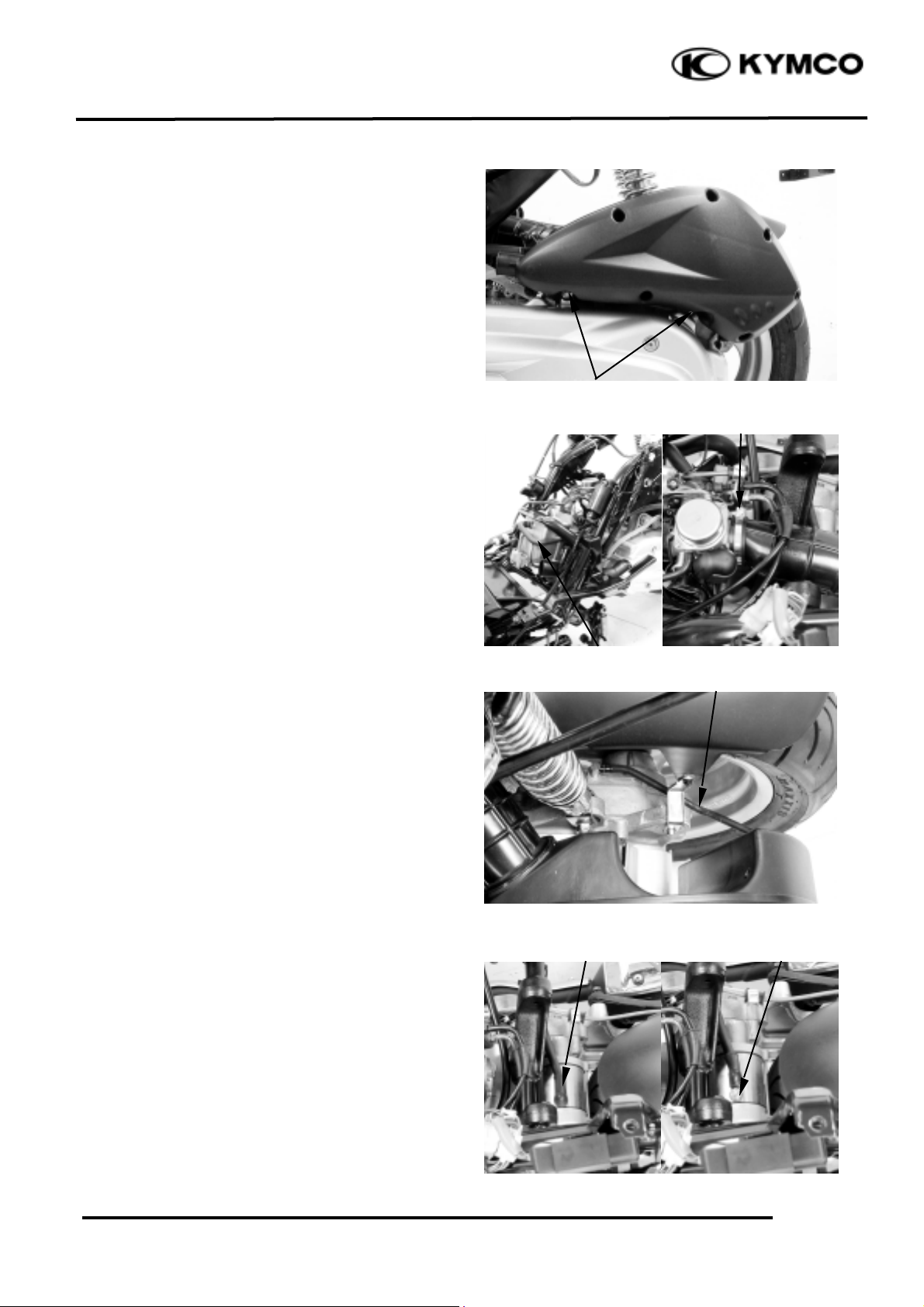
ENGINE HANGER REMOVAL
Remove rear carrier (
!2-6
), met-in box (
!2-
6
), center cover (
!2-7
), rear fender A (
!2-
8
), and rear body cover. (
!2-8
)
Remove two bolts on air cleaner.
Disconnect the oil vapor recovery tube and
loosen air cleaner tube band.
Disconnect the transmission case breather
hose, then remove air cleaner.
Open the rubber sheath and remove the nut,
then disconnect the starter motor wire.
Oil Vapor Recovery Tube
Bolts
Air Cleaner Tube Band
Intake Manifold Band
Transmission Case Breather Hose
Rubber Sheath
Nut
Page 4

5. ENGINE REMOVAL/INSTALLATION
5-3
YUP 25 0
Remove two bolts, then remove the starter
motor.
Remove the engine hanger nut, then remove
the engine hanger bolt (engine side).
Remove the engine hanger bolts (frame side)
and collar, then remove the engine hanger.
Inspect the engine hanger bushings and
stopper rubber for wear or damage.
Install the engine hanger in the reverse order
of remove.
Tighten the engine hanger bolt. (frame side)
Torque: 45_ 55N-m
Tighten the engine hanger bolt. (engine side)
Torque: 45_ 55N-m
ENGINE REMOVAL
Remove rear carrier (
!2-6
), met-in box (
!2-
6
), center cover (
!2-7
), rear fender A (
!2-
8
), rear body cover, (
!2-8
) and air cleaner.
(
!5-2
)
Disconnect the A.C. generator coupler and
relax the wire fetter.
A.C. Generator Coupler
Engine Hanger Bolts (frame side)
Bushing
Engine Hanger
Engine Hanger Bolts (engine side)
Nut
Bolts
Starter Motor
Wire Fetter
Collar
Bolt
Bolt
Page 5

5. ENGINE REMOVAL/INSTALLATION
5-4
YUP 25 0
Open the rubber sheath and remove the nut,
then disconnect the starter motor lead.
Disconnect rear brake fluid tube from clamps.
Remove the bolt on right crankcase cover for
disconnect ground wire lead.
Remove the two exhaust muffler joint lock
nuts.
Remove the three exhaust muffler lock bolts
to remove the exhaust muffler.
Remove the exhaust muffler and joint packing
collar.
Remove two bolts on the rear fork, then
remove rear brake caliper.
Rubber Sheath
Nut
Rear Brake Fluid Tube
Clamps
Bolts
Ground Wire Lead on Engine
Bolts
Nuts
Bolts
Rear Brake Caliper
Page 6

5. ENGINE REMOVAL/INSTALLATION
5-5
YUP 25 0
Remove three screws, then remove rear fender
C.
Remove the right rear shock absorber lower
bolt, rear axle nut, collar and two rear fork
bolt.
Remove the rear fork.
Disconnect two water hoses from water
ducts.
Disconnect oil pressure switch lead.
Disconnect secondary air vacuum tube and
fuel pump vacuum tube from intake manifold.
Disconnect secondary air cleaner fresh air
outlet hose from secondary air cleaner.
Disconnect thermo unit wire and radiator air
ventilated tube from thermostat.
Rear Fender C
Screw
Screws
Rear Axle Nut
Right Rear Shock Absorber Lower Bolt
Rear Fork Bolts
Water Hose
Oil Pressure Switch Lead
Fuel Pump
Vacuum Tube
Secondary Air
Vacuum Tube
Secondary Air Cleaner
Fresh Air Outlet Hose
Thermo
Unit Wire
Radiator Air
Ventilated Tube
Page 7

5. ENGINE REMOVAL/INSTALLATION
5-6
YUP 25 0
Loosen band screw, then disconnect
carburetor.
Remove the left rear shock absorber lower
bolt.
Remove engine hanger nut and bolt (engine
side).
Remove and pull the engine assembly to back
of the machine.
Put the engine assembly to below of the
machine.
Carburetor
Screw
Bolt
Bolt
Nut
Page 8

5. ENGINE REMOVAL/INSTALLATION
5-7
YUP 25 0
Move the engine assembly by rear wheel.
ENGINE ASSEMBLY
INSTALLATION
Install the engine assembly in the reverse
order of removal.
Tighten bolts and nuts
TORQUE VALUES
Rear axle nut
110_ 1
30
Rear shock absorber lower bolt 35_ 45
Engine hanger bolt (frame side) 45_ 55
Engine hanger bolt (engine side) 45_ 55
Rear caliper bolt 29_ 35
Exhaust muffler pipe nut 18_ 22
Exhaust muffler bolt 32_ 38
Rear fork bolt 29_ 35
After installation, inspect and adjust the
following:
• Throttle grip free play (!3-3)
• Fill the cooling system with coolant and
start the engine to bleed air from the system.
Bushes
• Apply grease onto the bushes before
install the engine assembly.
*
 Loading...