

Kymco MO X500 Service Manual - chap 14 (sterzo ruota ant ammortizzatore)

14.STEERING HANDLEBAR/FRONT WHEEL/
FRONT SHOCK ABSORBER
XCITING 500
14
__________________________________________________________________________________
__________________________________________________________________________________
__________________________________________________________________________________
__________________________________________________________________________________
14
__________________________________________________________________________________
STEERING HANDLEBAR/FRONT WHEEL/
FRONT SHOCK ABSORBER
__________________________________________________________________________________
SCHEMATIC DRAWING ------------------------------------------------- 14- 1
SERVICE INFORMATION------------------------------------------------ 14- 2
TROUBLESHOOTING----------------------------------------------------- 14- 3
FRONT WHEEL------------------------------------------------------------- 14- 4
FORK-------------------------------------------------------------------------- 14-12
STEERING HANDLEBAR ------------------------------------------------ 14-14
STEERING STEM----------------------------------------------------------- 14-20
14-0
14.STEERING HANDLEBAR/FRONT WHEEL/
FRONT SHOCK ABSORBER
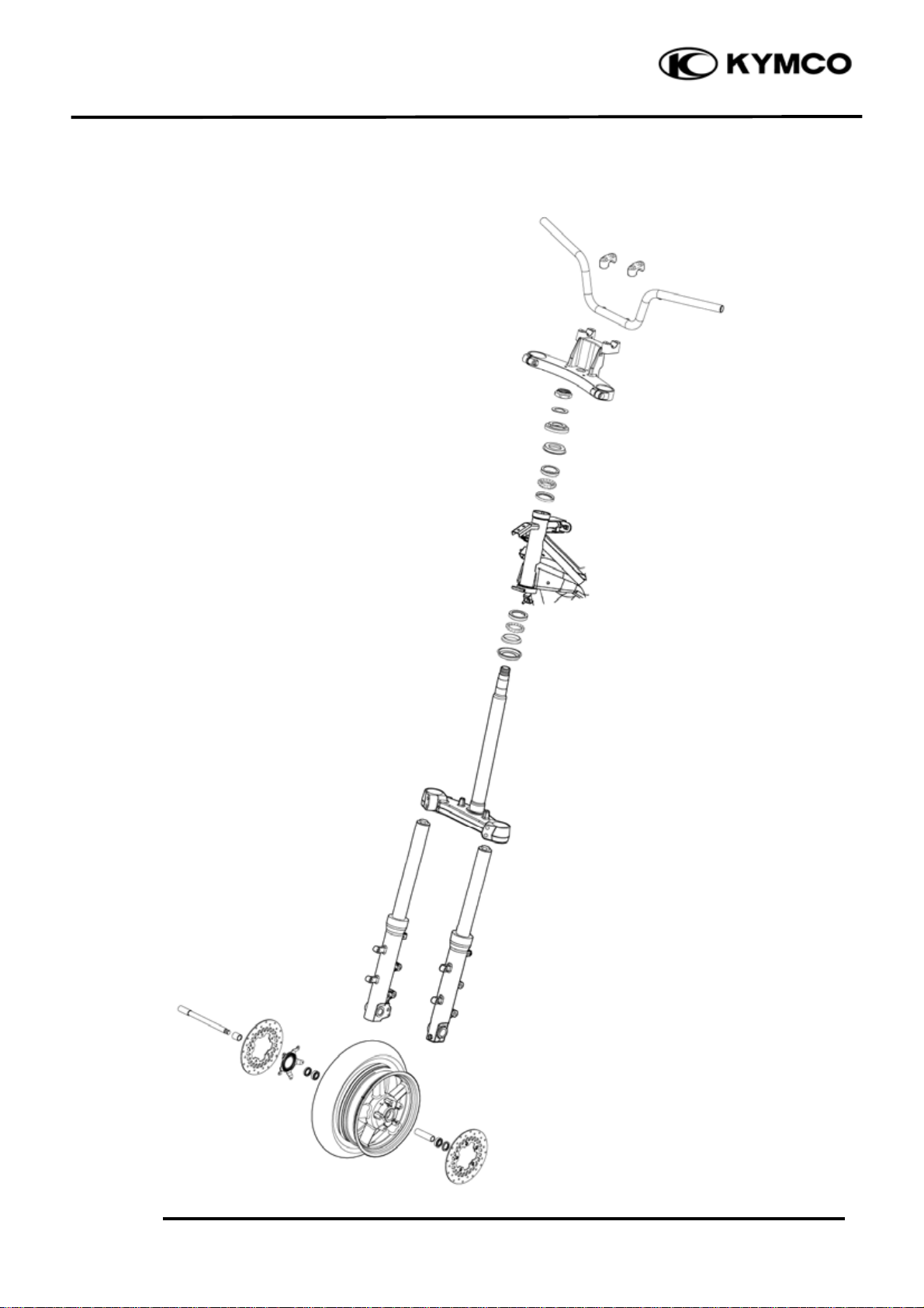
SCHEMATIC DRAWING
XCITING 500
14-1
14.STEERING HANDLEBAR/FRONT WHEEL/
⎯
)
y
m
)
⎯
m
)
⎯
⎯
)
⎯
)
⎯
)
FRONT SHOCK ABSORBER
SERVICE INFORMATION
GENERAL INSTRUCTIONS
• A contaminated brake disc or pad reduces stopping power. Discard contaminated parts and clean
a contaminated disc with a high quality brake degreasing agent.
• This section covers of the front wheel , fork, handlebar, and steering.
• A jack or other support is required to support the vehicle.
• Do not twist or bend the brake hose and pipe when servicing.
• Use genuine KYMCO replacement bolts and nuts for all suspension pivots and mounting points
• Refer to section 16 for brake system information.
SPECIFICATIONS
ITEM STANDARD SERVICE LIMIT
Minimum tire tread depth
2
, 29 psi
2
, 32psi
Cold tire pressure
Axle runout
Wheel rim runout
Driver onl
Driver and passenger225 kPa (2.25kgf/c
Radial
Axial
200 kPa (2.00 kgf/c
XCITING 500
Unit: mm (in)
1.6 (0.06
0.2 (0.008
2.0 (0.08
2.0 (0.08
TORQUE VALUES
Handlebar bolt 23 N•m (2.3 kgf•m, 17 lbf•ft)
Steering stem nut 62 N•m (6.2 kgf•m, 45 lbf•ft)
Steering stem lock nut 45 N•m (4.5 kgf•m, 32 lbf•ft)
Steering top thread 17 N•m (1.7 kgf•m, 12 lbf•ft)
Steering stem pinch bolt 23 N•m (2.3 kgf•m, 17 lbf•ft)
Front axle bolt 55 N•m (5.5 kgf•m, 40 lbf•ft)
Front brake disc bolt 42 N•m (4.3 kgf•m, 31 lbf•ft)
Lock bolt: replace with a new one.
Front fork bolt 23 N•m (2.3 kgf•m, 17 lbf•ft)
SPECIAL TOOLS
Long socket wrench E015
Bearing remover E037
Oil seal & bearing install driver E014
14-2

14.STEERING HANDLEBAR/FRONT WHEEL/
FRONT SHOCK ABSORBER
TROUBLESHOOTING
Hard steering Wheel turns hard
• Steering stem top thread too tight • Faulty front wheel bearings
• Worn or damaged steering bearings • Bent front axle
• Worn or damaged steering bearing races • Brake drug
• Bent steering stem
• Insufficient tire pressure Soft suspension
• Faulty front tire • Weak fork spring
• Insufficient fluid in fork
Steers to one side or does not track straight • Deteriorated fork fluid
• Damaged or loose steering bearings • Incorrect fork fluid weight
• Bent fork • Low tire pressure
• Bent front axle: wheel installed incorrectly
• Bent frame Hard suspension
• Faulty front tire • Bent fork tube
• Worn or damaged front wheel bearings • Too much fluid in fork
• Worn or damaged engine mounting bushings • Incorrect fork fluid weight
• Clogged fork fluid passage
Front wheel wobbling • High tire pressure
• Bent rim
• Worn or damaged front wheel bearings Front suspension noise
• Faulty front tire • Worn slider or fork tube bushing
• Loose front axle fasteners • Insufficient fluid in fork
• Loose fork fastener
XCITING 500
14-3
14.STEERING HANDLEBAR/FRONT WHEEL/
t
FRONT SHOCK ABSORBER
Holder bol
FRONT WHEEL
REMOVAL
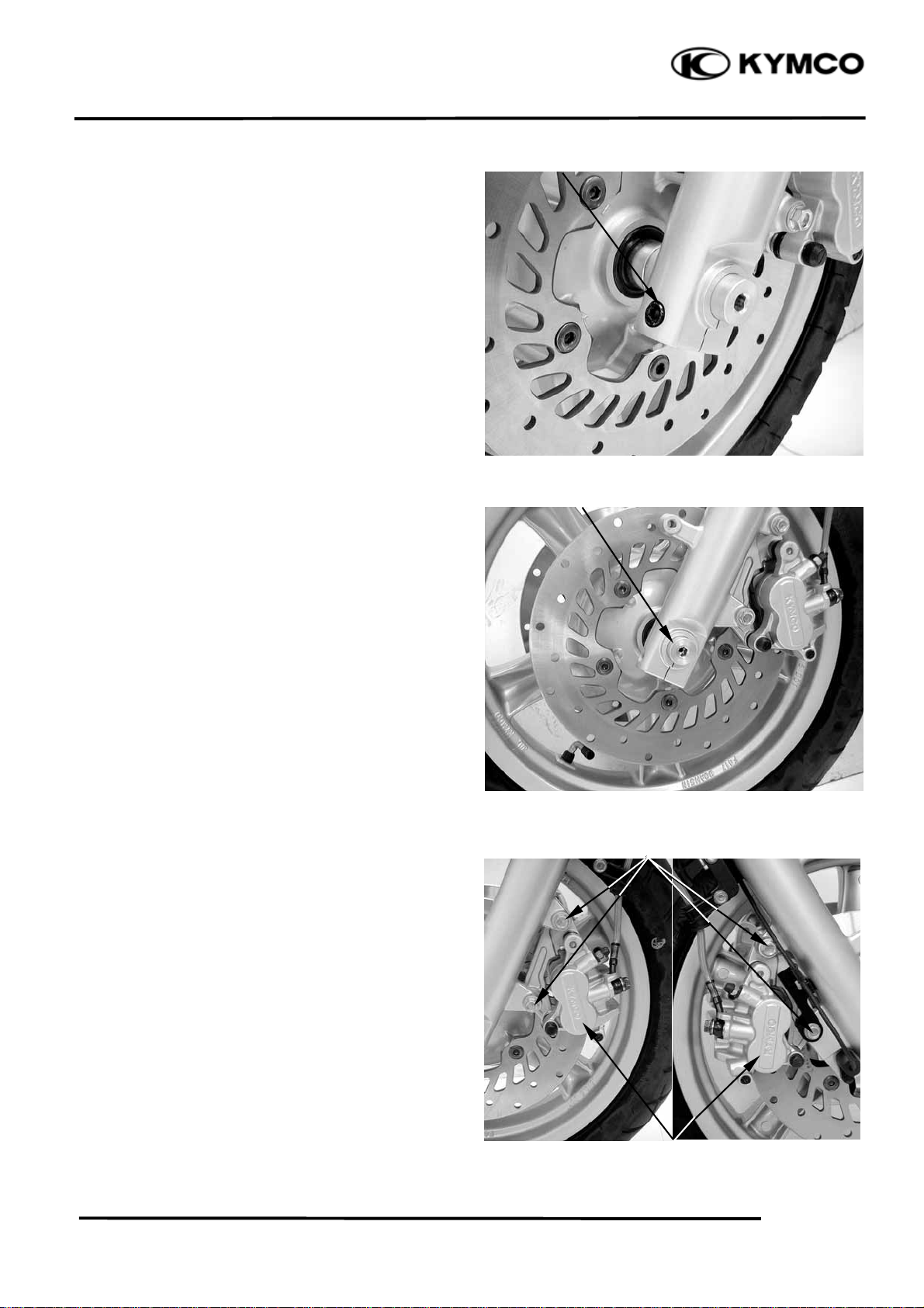
Loosen the front axle holder bolt.
Front Axle
Loosen the front axle bolt.
XCITING 500
Support the scooter securely using a hoist or
equivalent and raise the front wheel off the
ground.
Remove the right and left mount bolts and
front brake calipers.
Pull off the front axle out and remove the
front wheel.
NOTE:
Do not operate the front and rear brake
lever after removing the front wheel.
Bolts
Calipers
14-4

14.STEERING HANDLEBAR/FRONT WHEEL/
r
FRONT SHOCK ABSORBER
Remove the right and left side collar from the
wheel hub.
XCITING 500
Side Colla
INSTECTION
Axle
Place the axle in V-blocks and measure the
runout.
Actual runout is 1/2 the total indicator
reading.
Service limit: 0.20 mm (0.008 in)
Wheel
Check the rim runout by placing the wheel in
a truing stand.
Spin the wheel slowly and read the runout
using a dial indicator.
Actual runout is 1/2 the total indicator
reading.
Service limit: Radial: 0.20 mm (0.008 in)
Axial: 0.20 mm (0.008 in)
14-5
14.STEERING HANDLEBAR/FRONT WHEEL/
FRONT SHOCK ABSORBER
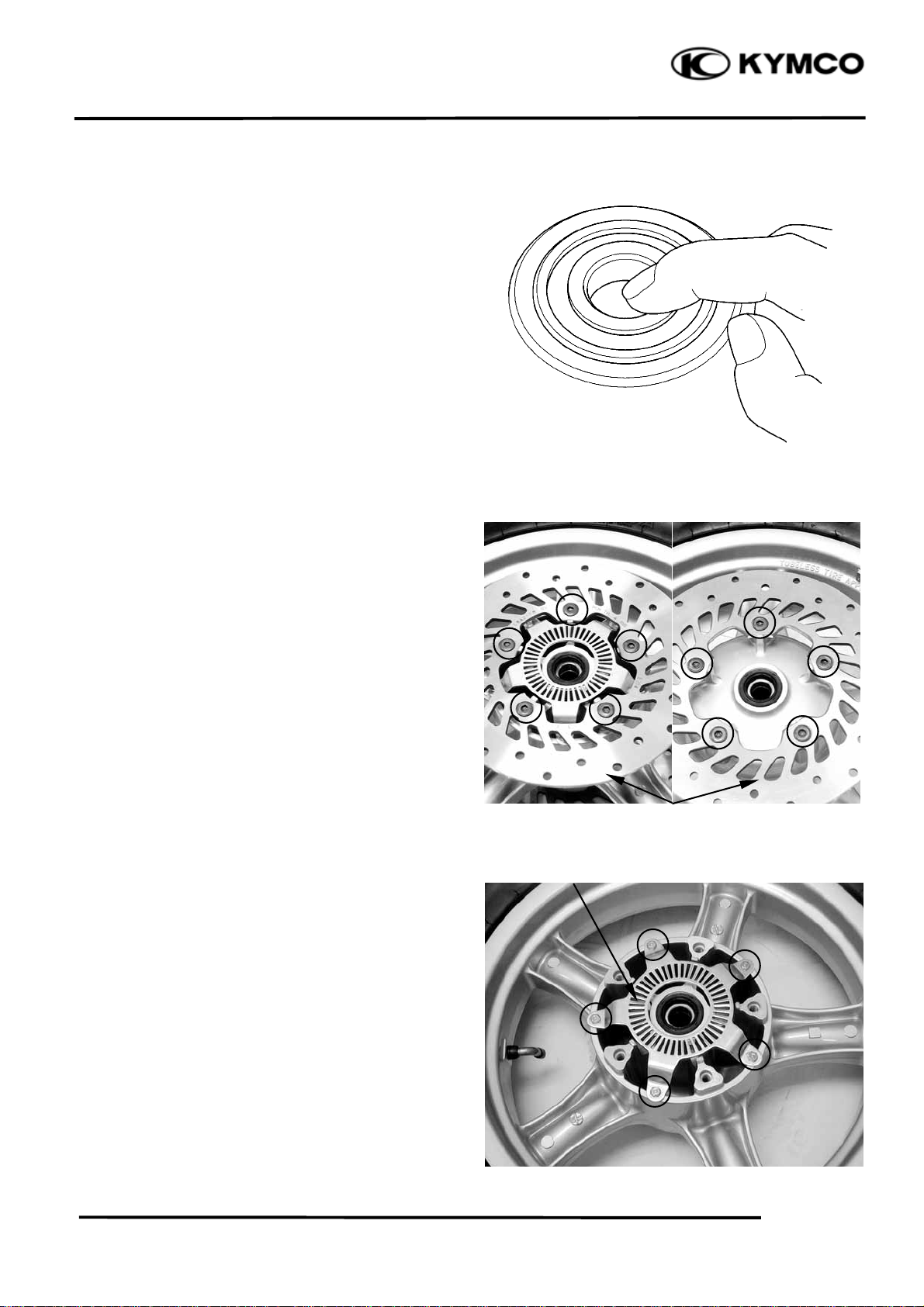
Wheel Bearing
Turn the inner race of each bearing with your
finger.
The bearings should turn smoothly and
quietly. Also check that the bearing outer race
fits tightly in the hub.
DIASSEMBLY
XCITING 500
Remove the right and left disc bolts and brake
discs.
Remove the bolts and speed sensor guide.
Discs
Speed Sensor Guide
Wheel Bearing
14-6
14.STEERING HANDLEBAR/FRONT WHEEL/
FRONT SHOCK ABSORBER
XCITING 500
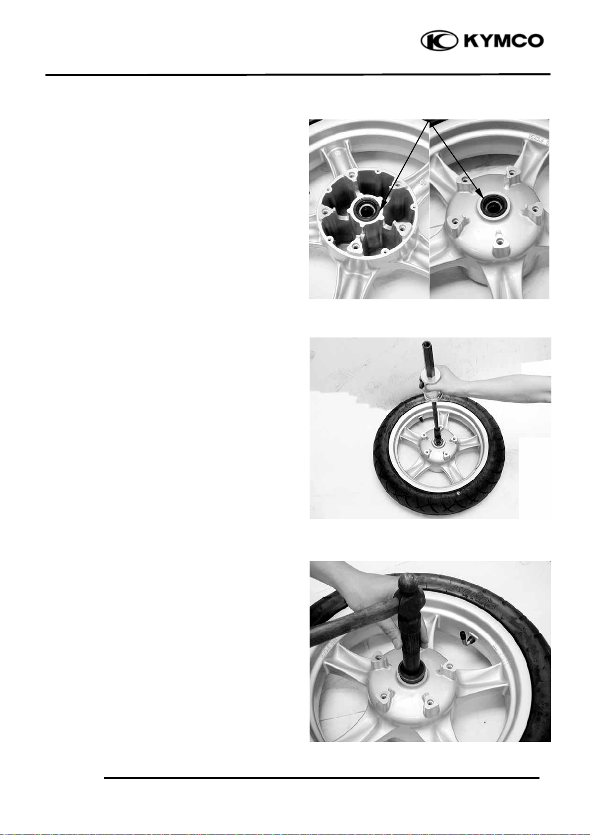
Remove the dust seals
Install the bearing remover into the bearing.
Drive the bearing out of the wheel hub.
Remove the distance collar and drive out the
other bearing.
Dust Seals
Special tool: Bearing remover E037
NOTE:
Replace the wheel bearings in pairs.
Do not reuse old bearings.
ASSEMBLY
Pack a new bearing cavities with grease.
Drive the new left bearing squarely with the
sealed side facing up until it is fully seated.
Special tool:
Oil seal & bearing install driver E014
14-7

14.STEERING HANDLEBAR/FRONT WHEEL/
r
FRONT SHOCK ABSORBER
XCITING 500
Install the distance collar.
Pack a new bearing cavities with grease.
Drive the new right bearing squarely with the
sealed side facing up until it is fully seated.
Distance Colla
Special tool:
Oil seal & bearing install driver E014
Apply grease to the new dust seal lips.
Install the dust seals into the wheel hub until
there are flush with the wheel hubs.
Dust Seals
14-8
 Loading...