

Page 1

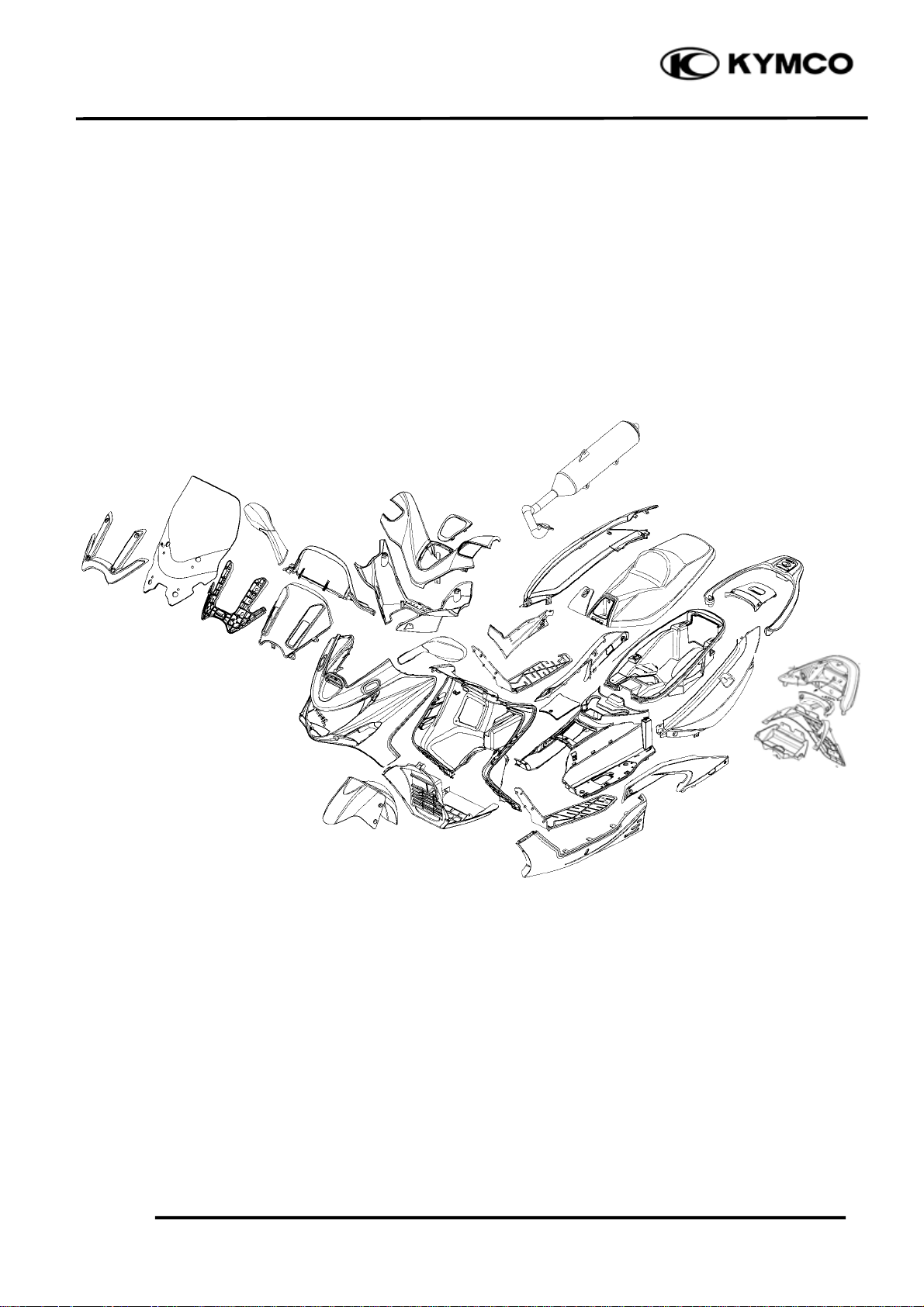
2. FRAME COVERS/ EXHAUST MUFFLER
XCITING 500
2
__________________________________________________________________________________
__________________________________________________________________________________
__________________________________________________________________________________
__________________________________________________________________________________
__________________________________________________________________________________
FRAME COVERS/EXHAUST MUFFLER
__________________________________________________________________________________
SCHEMATIC DRAWING ------------------------------------------------- 2- 1
SERVICE INFORMATION------------------------------------------------ 2- 2
2
TROUBLESHOOTING----------------------------------------------------- 2- 2
FRAME COVERS REMOVAL ------------------------------------------- 2- 3
EXHAUST MUFFLER ----------------------------------------------------- 2-15
2-0
Page 2
2. EXHAUST MUFFLER/FRAME COVERS
SCHEMATIC DRAWING
XCITING 500
2-1
Page 3

2. FRAME COVERS/ EXHAUST MUFFLER
XCITING 500
SERVICE INFORMATION
GENERAL INSTRUCTIONS
• When removing frame covers, use care not to pull them by force because the cover joint claws
may be damaged.
• Make sure to route cables and harnesses according to the Cable & Harness Routing.
TORQUE VALUES
Muffler mount bolt 35 N•m (3.5 kgf•m, 25 lbf•ft)
Exhaust pipe joint nut 20 N•m (2 kgf•m, 14 lbf•ft)
Exhaust pipe band bolt 21 N•m (2.1 kgf•m, 15 lbf•ft)
TROUBLESHOOTING
Noisy exhaust muffler
• Damaged exhaust muffler
• Exhaust muffler joint air leaks
Lack of power
• Caved exhaust muffler
• Clogged exhaust muffler
• Exhaust muffler air leaks
2-2
Page 4
2. EXHAUST MUFFLER/FRAME COVERS
N
r
N
t
N
r
XCITING 500
FRAME COVERS REMOVAL
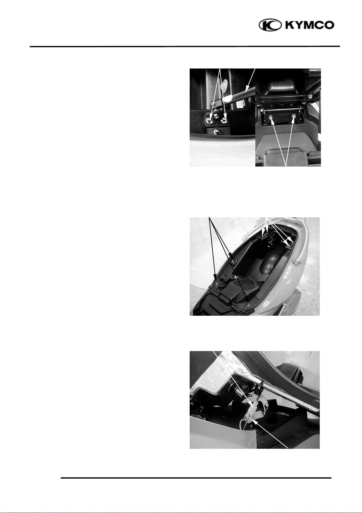
SEAT
REMOVAL
Unlock the seat with the ignition key.
Open the seat.
Remove the two nuts and seat damper unit.
Remove the two nuts and the seat.
INSTALLATION
Installation is in the reverse order of the
removal.
After installation, check the seat installation
by moving the seat.
LUGGAGE BOX
REMOVAL
Remove the seat (page 2-3).
uts
uts
Damper Uni
uts
Screws
Remove the four screws and three nuts.
Raise the luggage box, disconnect the
luggage box light and accessory socket
connectors.
INSTALLATION
Installation is in the reverse order of removal.
Luggage Box Light Connecto
Accessory Socket Connecto
2-3
Page 5
2. FRAME COVERS/ EXHAUST MUFFLER
t
XCITING 500
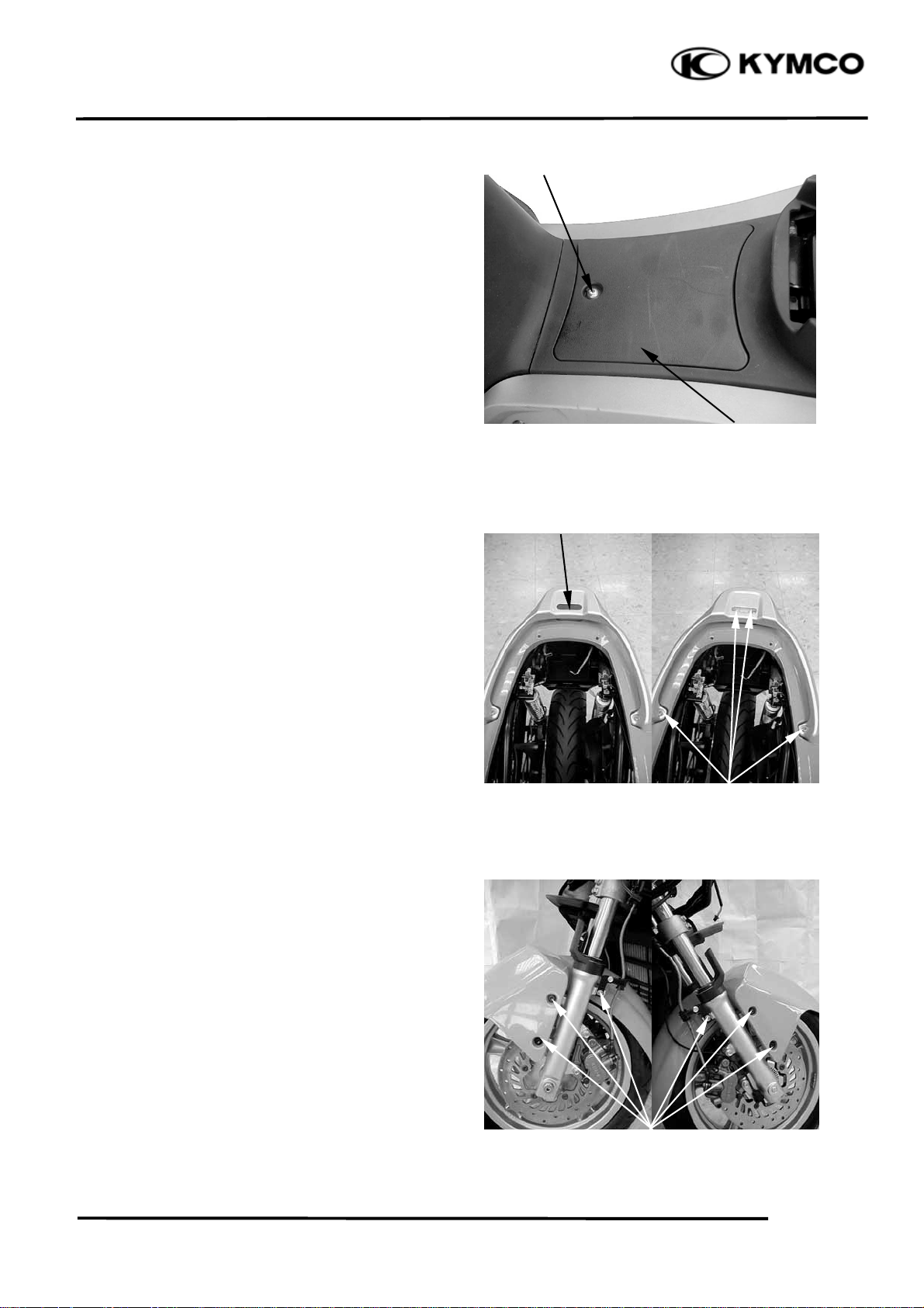
SPARK PLUG MAINTENANCE LID
REMOVAL
Remove the bolt and lid.
INSTALLATION
Installation is in the reverse order of removal.
REAR SPOILER
REMOVAL
Unlock the seat with the ignition key.
Open the seat.
Bol
Spark Plug Maintenance Lid
Rubber Cap
Remove the rubber cap.
Remove four bolts and rear spoiler.
INSTALLATION
Installation is in the reverse order of removal.
FRONT FENDER
RE MOVAL
Remove the six bolts and front fender.
INSTALLATION
Installation is in the reverse order of removal.
Bolts
Bolts
2-4
Page 6
2. EXHAUST MUFFLER/FRAME COVERS
r
t
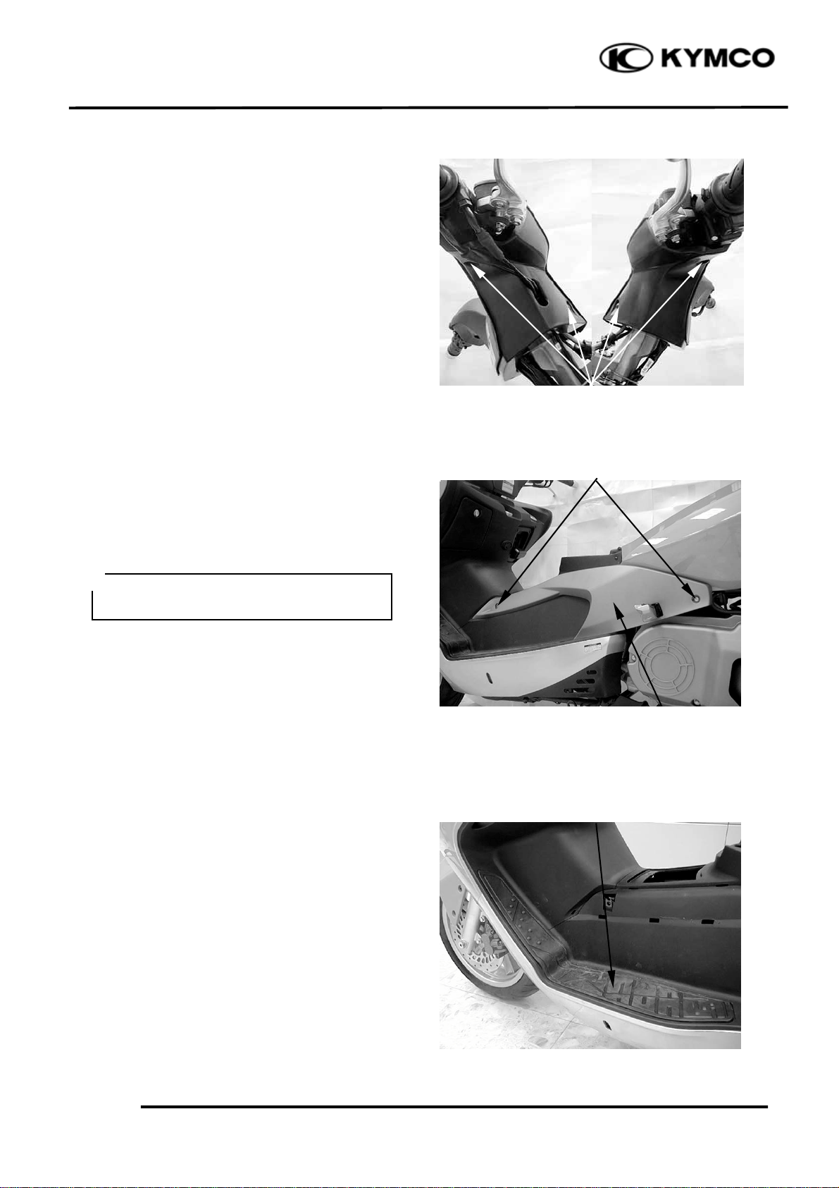
UPPER HANDLEBAR COVER
REMOVAL
Remove four screws and upper handlebar
cover.
INSTALLATION
Installation is in the reverse order of removal.
Bolts
RIGHT/LEFT CENTER BODY COVER
REMOVAL
Remove the two bolts and right/left center
body cover.
XCITING 500
Screws
*
Be careful not to damage the tabs on the
center body cover.
INSTALLATION
Installation is in the reverse order of removal.
RIGHT/LEFT FLOOR SKIRT
REMOVAL
Remove the floor mat.
Remove the center body cover (page 2-5).
Center Body Cove
Floor Ma
2-5
Page 7

2. FRAME COVERS/ EXHAUST MUFFLER
Screws
Remove the seven screws.
Screws
Remove two screws.
XCITING 500
Remove the floor skirt.
*
Be careful not to damage the tabs on the
floor skirt.
INSTALLATION
Installation is in the reverse order of removal.
FLOORBOARD
REMOVAL
Remove right and left center body cover
(page 2-5).
Remove the right and left floor skirt (page 2-
5).
Remove the luggage box (page 2-3).
Bolts
Remove six bolts, four screws and
floorboard.
INSTALLATION
Installation is in the reverse order of removal.
Screws
2-6
Page 8

2. EXHAUST MUFFLER/FRAME COVERS
r
t
XCITING 500
LICENCE LIGHT
REMOVAL
Remove two screws.
Disconnect the license light connector and
remove the license light.
INSTALLATION
Installation is in the reverse order of removal.
REAR FENDER
REMOVAL
Remove the licence light (page 2-7).
Remove two screws.
Screws Connecto
Remove two nuts and rear fender.
INSTALLATION
Installation is in the reverse order of removal.
2-7
Screws
Nu
s
Page 9

2. FRAME COVERS/ EXHAUST MUFFLER
r
XCITING 500
RIGHT/LEFT SIDE BODY COVER
REMOVAL
Remove the luggage box (page 2-3).
Remove the floorboard (page 2-6).
Remove the rear spoiler (page 2-4).
Remove two bolts.
Raise the side body cover, disconnect the
taillight/rear turn signal light connector and
remove the side body cover.
Bolts
INSTALLATINON
Installation is in the reverse order of removal
REAR BODY COVER
REMOVAL
Remove the luggage box (page 2-3).
Remove the rear spoiler (page 2-4).
Remove two screws and rear body cover.
*
Be careful not to damage the tabs on the
rear body cover.
Taillight/Rear Turn Signal Light Connecto
Screws
INSTALLATION
Installation is in the reverse order of removal.
2-8
Page 10

2. EXHAUST MUFFLER/FRAME COVERS
r
XCITING 500
TAILIGHT/REAR TURN SIGNAL
LIGHT
REMOVAL
Remove the side and rear body cover (page 2-
8).
Remove eight screw and taillight/rear turn
signal light.
INSTALLATION
Installation is in the reverse order of removal.
REAR LOWER COVER
REMOVAL
Remove the side body cover (page 2-8).
Screws
Screws
Remove the rear lower cover.
REARVIEW MIRROR
REMOVAL
Remove bolts lid.
Remove three bolts and rearview mirror.
Rear Lower Cove
2-9
Lid Bolts
Page 11

2. FRAME COVERS/ EXHAUST MUFFLER
r
t
Rearview Mirror Holde
Remove the two bolts, rearview mirror holder
and seat.
INSTALLATION
Installation is in the reverse order of removal
Bolts Holder Sea
Screws
WINDSHIELD
XCITING 500
REMOVAL
Remove four screws and windshield garnish.
Remove four bolts and windshield.
*
Be careful not to scratch or damage the
windshield surface.
INSTALLATION
Installation is in the reverse order of removal.
Windshield Garnish
Windshield
2-10
Page 12

2. EXHAUST MUFFLER/FRAME COVERS
r
XCITING 500
FRONT COVER
REMOVAL
Remove the rearview mirrors (page 2-9).
Remove six screws.
Remove two screws.
Screws
Screws
Remove one screw.
Disconnect headlight and turn signal light
connectors.
INSTALLATION
Installation is in the reverse order of removal.
2-11
Turn Signal Light Connectors
Screw Headlight Connecto
Page 13

2. FRAME COVERS/ EXHAUST MUFFLER
r
XCITING 500
HEADLIGHT
REMOVAL
Remove the front cover (page 2-11).
Remove six screws and headlight.
INSTALLATION
Installation is in the reverse order of removal.
TURN SIGNAL LIGHT
REMOVAL
Remove the front cover (page 2-11).
Screws
Remove three screws and turn signal light.
INSTALLATION
Installation is in the reverse order of removal.
FRONT METER VISOR
REMOVAL
Remove the windshield (page 2-10).
Remove the front cover (page 2-11).
Remove four bolts and windshield holder.
Screws
Windshield Holde
Bolts
2-12
Page 14

2. EXHAUST MUFFLER/FRAME COVERS
r
XCITING 500
Remove two screws and front meter visor.
INSTALLATION
Installation is in the reverse order of removal.
MEER PANEL
REMOVAL
Remove the front cover (page 2-11).
Remove the front meter visor (page 2-12).
Screw
Remove four screws.
Disconnect the speedometer connector and
remove meter panel.
INSTALLATION
Installation is in the reverse order of removal.
Screws
Speedometer Connecto
2-13
Bolts
Page 15

2. FRAME COVERS/ EXHAUST MUFFLER
r
Screws
METER
REMOVAL
Remove the meter panel (page 2-13).
Remove two screws and meter.
Shutte
INNER COVER
REMOVAL
Remove the front cover (page 2-11).
Remove the floorboard (page 2-6).
Remove the meter panel (page 2-13).
XCITING 500
Remove the shutter screw and shutter.
Turn the fuel fill cap garnish
counterclockwise and remove it.
Remove three screws and disconnect the fuel
fill duct.
Screw
Cap Garnish
Screws
2-14
Page 16

2. EXHAUST MUFFLER/FRAME COVERS
r
XCITING 500
Remove four fasteners.
Remove the inner cover.
INSTALLATION
Installation is in the reverse order of removal.
FRONT LOWER COVER
REMOVAL
Remove the front cover (page 2-11).
Remove the right and left floor skirt (page 2-
5).
Fasteners
Remove two bolts and front lower cover.
EXHAUST MUFFLER
REMOVAL
Remove four screws and muffler protector.
Bolts
Muffler Protecto
2-15
Screws
Page 17

2. FRAME COVERS/ EXHAUST MUFFLER
XCITING 500
Loosen the exhaust pipe band bolt.
Remove three muffler mount bolts and
muffler from the exhaust pipe.
Remove the exhaust pipe joint nuts and
exhaust pipe.
Band Bolt Mount bolts
Remove the gaskets.
INSTALLATION
Replace the gaskets with new ones.
Install the exhaust pipe and tighten the joint
nuts.
Torque: 20 N•m (2 kgf•m, 14 lbf•ft)
Install the muffler and tighten the mount
bolts.
Torque: 35 N•m (3.5 kgf•m, 25 lbf•ft)
Install and tighten the band bolts.
Torque: 21 N•m (2.1 kgf•m, 15 lbf•ft)
Joint Nuts
Gaskets
2-16
 Loading...