

Page 1

19. ELECTRIC STARTER
XCITING 500
19
__________________________________________________________________________________
__________________________________________________________________________________
__________________________________________________________________________________
__________________________________________________________________________________
__________________________________________________________________________________
ELECTRIC STARTER
__________________________________________________________________________________
STARTING SYSTEM LAYOUT ----------------------------------------- 19-1
SERVICE INFORMATION------------------------------------------------ 19-2
TROUBLESHOOTING----------------------------------------------------- 19-2
STARTER MOTOR --------------------------------------------------------- 19-5
STARTER RELAY SWITCH---------------------------------------------- 19-7
19
19-0
Page 2
19. ELECTRIC STARTER
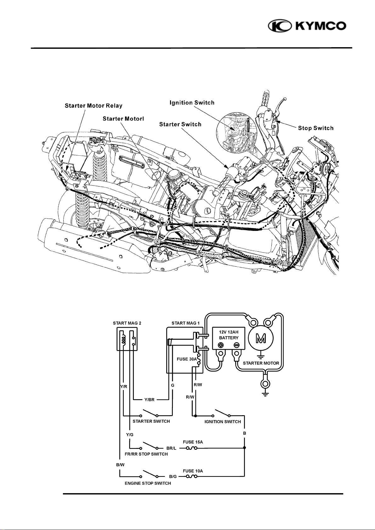
STARTING SYSTEM LAYOUT
XCITING 500
STARTING CIRCUIT
19-1
Page 3
19. ELECTRIC STARTER
N
XCITING 500
SERVICE INFORMATION
GENERAL
• Always turn the ignition switch to “OFF” before servicing the starter motor. The motor could
suddenly start, causing serious injury.
• The starter motor can be serviced with the engine in the frame.
• When checking the starter system, always follow the steps in the troubleshooting flow chart
(page 19-2).
• A weak battery may be unable to turn the starter motor quickly enough, or supply adequate
ignition current.
• If the current is kept flowing through the starter motor to turn it while the engine is not cranking
over, the starter motor may be damaged.
• See section 12 for starter clutch servicing.
• See section 20 for following components:
ä Ignition switch
ä Starter switch
ä Brake light switch
TROUBLESHOOTING
• Check for the following before troubleshooting:
─ Blown main fuse (30A) and sub fuse (10 A)
─ Loose battery and starter motor cable
─ Discharged battery
• The starter motor can turn with the following conditions:
─ Ignition switch ON
─ Engine stop switch in RUN
─ Rear brake lever fully squeezed
─ Side stand retracted
─ Starter switch pushed
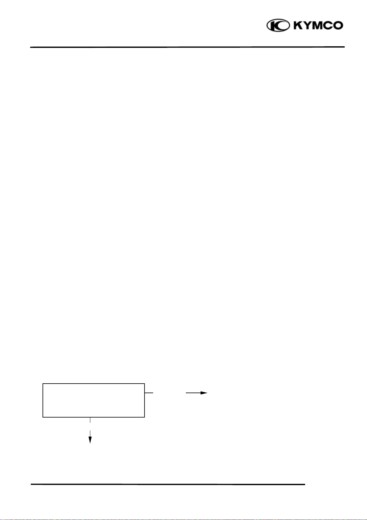
Starter motor will not turn
Check for loose or poorly
connected battery terminals
and opened or shorted battery
cable.
ormal
Abnormal
•Poorly connected battery terminals.
•Open or short circuit in battery.
(Go to following page)
19-2
Page 4

19. ELECTRIC STARTER
r
N
N
N
N
(From previous page)
XCITING 500
Check for loose or poorly
connected starter relay switch
terminals.
ormal
Check for loose or poorly
connected or broken starter
motor cable.
ormal
With the ignition switch
turned to “ON”, push the
starter switch and check for a
click sound from the starter
relay switch.
o clicks
Abnormal
Abnormal
Clicks
•Poorly connected terminal
•Poorly connected starter motor cable.
•Open circuit in starter motor cable.
Connect the starter motor terminal
directly to the battery positive
terminal (Because a large amount of
current flows, do not use a thin wire).
Starter motor turns
Starter moto
does not turn
Check the starter relay coil
ground line (page 19-7)
ormal
(Go to following page)
Abnormal
•Faulty starter motor.
•Loose or disconnected starter motor cable.
•Faulty starter relay switch.
•Faulty side stand switch.
•Loose or poor contact of connector.
•Open or short circuit in wire harness.
19-3
Page 5

19. ELECTRIC STARTER
N
N
(From previous page)
XCITING 500
Check the starter relay voltage
(page 19-7).
Battery voltage registers
Check the starter relay voltage
(page 19-7).
ormal
•Loose or poor starter relay connector contact.
o voltage
Abnormal
•Faulty engine stop switch.
•Faulty starter switch.
•Loose or poor contact of connector.
•Open circuit in wire harness.
•Faulty starter relay.
19-4
Page 6

19. ELECTRIC STARTER
t
r
STARTER MOTOR
INSPECTION
Remove the luggage box (page 2-3).
Disconnect the starter motor cable from the
starter relay switch.
Turn the ignition switch to “ON”.
Connect the starter motor cable directly to the
battery positive terminal.
If the starter motor does not turn, the starter
motor is faulty.
REMOVAL
Remove the carburetor (page 5-5).
XCITING 500
Starter Motor Cable
Nu
Turn the ignition switch turned to “OFF”
Release the rubber cap and remove the terminal
nut to disconnect the starter motor cable from
the starter motor.
Remove the two bolts and starter motor.
Rubber Cap
Starter Moto
19-5
Bolts
Page 7

19. ELECTRIC STARTER
t
r
XCITING 500
INSTALLATION
Coat a new O-ring with engine oil and install it
into the starter motor groove.
Install the starter motor into the crankcase.
Install the two bolts and tighten them securely.
O-ring
Starter Moto
Connect the starter motor cable to motor
terminal with the terminal nut and tighten it.
Bolts
Starter Motor Cable
Nu
19-6
Page 8

19. ELECTRIC STARTER
r
STARTER RELAY SWITCH
INSPECTION
Remove the luggage box (page 2-3).
Retracted the side stand.
Turn the ignition switch to “ON” and engine
stop switch on.
Squeeze the rear brake lever fully and push the
starter switch.
The coil is normal if the starter relay switch
clicks.
If you do not hear the switch click. Inspect the
relay switch using the procedure below.
GROUND LINE INSPECTION
Disconnect the starter relay switch connector.
Check for continuity between the Green wire
terminal and ground.
XCITING 500
Starter Relay Switch
There should be continuity.
VOLTAGE INSPECTION
Connect the starter relay switch connector.
Turn the ignition switch ON and engine stop
switch to RUN.
Measure the starter relay switch Yellow/Red
wire terminal and ground.
If the battery voltage appears only when the rear
brake lever is squeezed fully and starter switch
is pushed, the circuit is normal.
Starter Relay Connecto
19-7
Starter Relay Switch
Page 9

19. ELECTRIC STARTER
XCITING 500
CONTINUTY INSPECTION
Disconnect the starter relay switch connector
and cables.
Connect a fully charged 12 V battery positive
wire to the relay switch Yellow/Red wire
terminal and negative wire to the Green wire
terminal.
There should be continuity between the cable
terminals while the battery is connected, and no
continuity when the battery is disconnected.
Starter Relay Switch
19-8
 Loading...