

Page 1

6. COOLING SYSTEM
XCITING 500
6
__________________________________________________________________________________
__________________________________________________________________________________
__________________________________________________________________________________
__________________________________________________________________________________
__________________________________________________________________________________
COOLING SYSTEM
__________________________________________________________________________________
SYSTEM FLOW PATTERN----------------------------------------------- 6- 1
SERVICE INFORMATION------------------------------------------------ 6- 2
TROUBLESHOOTING----------------------------------------------------- 6- 4
COOLING SYSTEM TESTING------------------------------------------- 6- 5
COOLANT REPLACEMENT --------------------------------------------- 6- 5
THERMOSTAT-------------------------------------------------------------- 6- 8
WATER PUMP -------------------------------------------------------------- 6-10
RADIATOR ------------------------------------------------------------------ 6-13
FAN MOTOR SWITCH ---------------------------------------------------- 6-16
WATER TEMPERATURE SENSOR ------------------------------------ 6-17
RAIDATOR RESERVE TANK ------------------------------------------- 6-18
6
6-0
Page 2
6. COOLING SYSTEM
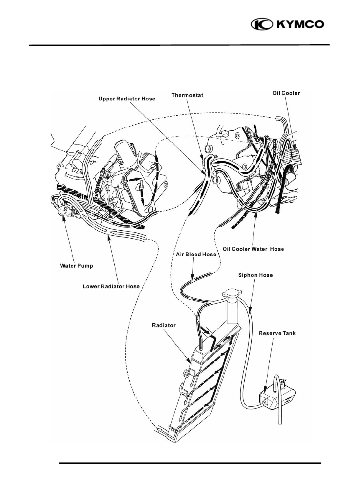
SCHEMATIC DRAWING
XCITING 500
6-1
Page 3

6. COOLING SYSTEM
XCITING 500
SERVICE INFORMATION
GENERAL INSTRUCTIONS
WARING:
Removing the radiator cap while the engine is hot can allow the coolant to spray out,
seriously scalding you. Always let the engine and radiator cool down before removing the
radiator cap.
CAUTION:
Radiator coolant is toxic. Keep it away from eyes, mouth, skin and clothes.
• If any coolant gets in your eyes, rinse them with water and consult a physician immediately.
• If any coolant in swallowed, induce vomiting, gargle and consult a physician immediately.
• If any coolant gets on your skin or clothes, rinse thoroughly with plenty of water.
NOTE:
Use coolant with silicate inhibitors may cause premature wear of water pump seals or blockage of
radiator passages. Using tap water may cause engine damage.
• This section covers service of the cooling system.
• These services can be done with the engine installed in the frame.
• Add coolant at the reserve tank. Do not remove the radiator cap except to refill or drain the
system.
• All cooling system services can be done with the engine in the frame.
• Avoid spilling coolant on painted surfaces.
• After servicing the system, check for leaks with a cooling system tester.
6-2
Page 4
6. COOLING SYSTEM
p
SPECIFICATIONS
ITEM SPECIFICATIONS
Radiator and engine 2 liter (2.1 US qt, 1.76 lmp qt)Coolant capacity
Reserve tank 0.37 liter (0.4 US qt, 0.33 lmp qt)
Radiator cap relief pressure 108 kPa (1.1 kgf/cm2, 16 psi)
Thermostat
Standard coolant concentration 1:1 mixture with soft water
COOLANT GRAVITY CHART
Tem
. ℃
Coolant
concentration
5% 1.009 1.009 1.008 1.008 1.007 1.006 1.005 1.003 1.001 0.009 0.997
10% 1.018 1.107 1.017 1.016 1.015 1.014 0.013 1.011 1.009 1.007 1.005
15% 1.028 1.027 1.026 1.025 1.024 1.022 1.020 1.018 1.016 1.014 1.012
20% 1.036 1.035 1.034 1.033 1.031 1.029 1.027 1.025 1.023 1.021 1.019
25% 1.045 1.044 1.043 1.042 1.040 1.038 1.036 1.034 1.031 1.028 1.025
30% 1.053 1.051 1.051 1.049 1.047 1.045 1.043 1.041 1.038 1.035 1.032
35% 1.063 1.062 1.060 1.058 1.056 1.054 1.052 1.049 1.046 1.043 1.040
40% 1.072 1.070 1.068 1.066 1.064 1.062 1.059 1.056 1.053 1.050 1.047
45% 1.080 1.078 1.076 1.074 1.072 1.069 1.056 1.063 1.062 1.057 1.054
50% 1.086 1.084 1.082 1.080 1.077 1.074 1.071 1.068 1.065 1.062 1.059
55% 1.095 1.093 1.091 1.088 1.085 1.082 1.079 1.076 1.073 1.070 1.067
60% 1.100 1.098 1.095 1.092 1.089 1.086 1.083 1.080 1.077 1.074 1.071
Begin to open 80 - 84°C (176 - 183°F)
Fully open 95°C (203°F)
Valve lift 8 mm (0.3 in) minimum
0 5 10 15 20 25 30 35 40 45 50
XCITING 500
COOLANT MIXTURE (WITH ANTI-RUST AND ANTI-FREEZING EFFECTS)
Freezing Point Mixing Rate KYMCO SIGMA Coolant Concentrate Distilled Water
-9℃ 20%
-15℃ 30% 425cc 975cc
-25℃ 40%
-37℃ 50%
-44.5℃ 55%
Cautions for Using Coolant:
• Use coolant of specified mixing rate. (The mixing rate of 425cc KYMCO SIGMA coolant
concentrate + 975cc distilled water is 30%.)
• Do not mix coolant concentrate of different brands.
• Do not drink the coolant which is poisonous.
• The freezing point of coolant mixture shall be 5℃lower than the freezing point of the riding
area.
6-3
Page 5

6. COOLING SYSTEM
TORQUE VALUES
Water pump cover bolt 13 N•m (1.3 kgf•m, 9 lbf•ft)
Fan motor bolt 5 N•m (0.53 kgf•m, 3.8 lbf•ft)
Radiator shroud mounting nut 9 N•m (0.9 kgf•m, 6.5 lbf•ft)
TROUBLESHOOTING
Engine temperature too high
• Faulty radiator cap
• Faulty temperature gauge or thermosensor
• Air in system
• Thermostat stuck closed
• Insufficient coolant
• Passages blocked in radiator, hoses or water jacket
• Faulty cooling fan motor
• Faulty fan motor switch
• Faulty water pump
XCITING 500
Engine temperature too low
• Faulty temperature gauge or thermosensor
• Thermostat stuck open
• Faulty fan motor switch
Coolant leak
• Faulty water pump mechanical seal
• Deteriorated O-rings
• Faulty radiator cap
• Damaged or deteriorated cylinder head gasket
• Loose hose connection or clamp
• Damaged or deteriorated hoses
6-4
Page 6
6. COOLING SYSTEM
r
r
COOLING SYSTEM TESTING
XCITING 500
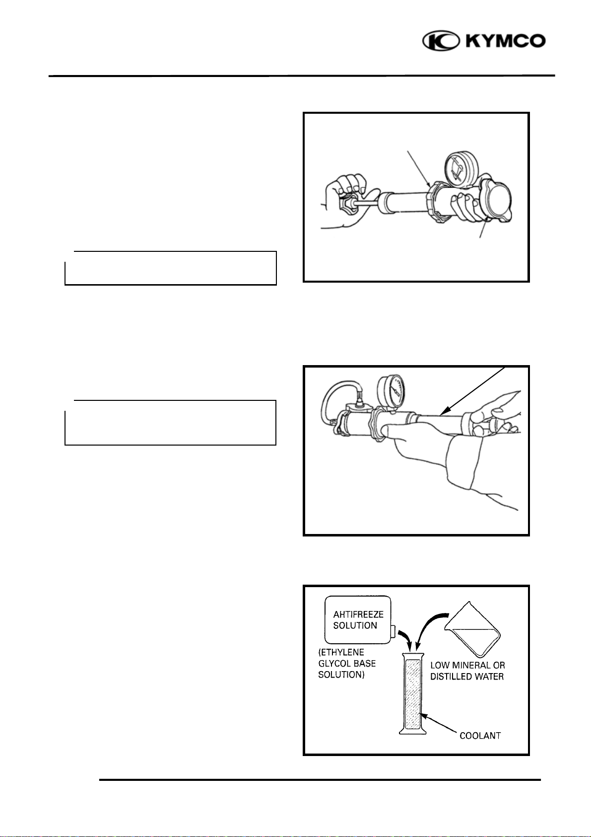
RADIATOR CAP INSPECTION
Remove the radiator cap (page 6-6).
Pressure test the radiator cap.
Replace the radiator cap if it does not hold
pressure, or if relief pressure is too high or
too low.
It must hold the specified pressure for at
least six seconds.
*
Before installing the cap in the tester,
wet the sealing surfface.
Radiator Cap Relief Pressure:
108 kPa (1.1 kg/cm², 16 psi)
Pressurize the radiator, engine and hoses,
and check for leaks.
*
Excessive pressure can damage the
cooling system components. Do not
exceed 137 kPa (1.4 kg/cm², 20 psi).
Cap Teste
Radiator Cap
Cap Teste
Repair or replace components if the system
will not hold the specified pressure for at
least six seconds.
COOLANT REPLACEMENT
PREPARATION
● The effectiveness of coolant decreases
with the accumulation of rest or if there is
a change in the mixing proportion during
usage. Therefore, for best performance
change the coolant regularly as specified
in he maintenance schedule.
● Mix only distilled, low mineral water
with the antifreeze.
Recommended mixture:
1:1 (Distilled water and antifreeze)
6-5
Page 7

6. COOLING SYSTEM
t
XCITING 500
REPLACEMENT/AIR BLEEDING
Remove the front cover (page 2-11).
Remove the front lower cover (page 2-15).
*
When filling the system or reserve tank
with coolant (checking the coolant
level), place the scooter in a vertical
position on a flat, level surface.
Remove the radiator cap.
Disconnect the water lower hose and drain
the coolant from the system.
Radiator Cap
Remove the floor mat.
Remove the screw and reserve tank lid.
Water Lower Hose
Reserve Tank Lid Screw
Floor Ma
6-6
Page 8

6. COOLING SYSTEM
Remove the reserve tank cap and drain the
coolant from the reserve tank.
Reconnect the water lower hose securely.
Place the scooter on its center stand on a
flat, level surface.
Fill the reserve tank to the upper level line.
XCITING 500
Reserve Tank Cap
Fill the system with the recommended
coolant through the filler opening up to the
filler neck.
6-7
Upper Level Line
Filler Neck
Page 9

6. COOLING SYSTEM
t
r
Bleed air from the system as follow:
1. Start the engine and let it idle for 2−3
minutes.
2. Snap the throttle three to four times to
bleed air from the system.
3. Stop the engine and add coolant to the
proper level if necessary. Reinstall the
radiator cap.
4. Check the level of coolant in the reserve
tank and fill to the upper level if it is
low.
THERMOSTAT
REMOVAL
Remove the floorboard (page 2-6).
Remove the ignition coil (page 18-5).
XCITING 500
Nu
Remove the nut and thermostat housing
stay from the frame.
Remove the bolts, housing stay and
thermostat housing cover.
Housing stay
Housing Stay Housing Cove
Bolts
6-8
Page 10

6. COOLING SYSTEM
r
t
t
Remove the O-ring from the housing cover.
Remove the thermostat.
INSPECTION
Visually inspect the thermostat for damage.
XCITING 500
Thermosta
O-ring
Thermosta
Heat the water with an electric heating
element to operating temperature for five
minutes.
Suspend the thermostat in heated water to
check its operation.
*
● Keep flammable materials away from
the electric heating element.
● Do not let the thermostat or
thermometer touch the pan, or you will
get false readings.
Replace the thermostat if the valve stays
open at room temperature, or if it respond at
temperatures other than those specified.
Thermostat begin to open:
80−84°C (176−183°F)
Valve lift:
8 mm (0.3 in) minimum at 95°C (203°F)
Thermostat
Thermomete
6-9
Page 11

6. COOLING SYSTEM
INSTALLATION
Install the thermostat into the housing with
its air bleed hole facing up and aligning
bleed hole with the tab in the housing.
Install a new O-ring into the housing cover
groove.
XCITING 500
Air Bleed Hole
Tab Align
Install the housing cover and housing stay
to the housing.
Tighten the bolts securely.
Install the housing stay to the frame.
Tighten the nut securely.
Fill the system with recommended coolant
and bleed the air (page 6-6).
WATER PUMP
MECHANICAL SEAL INSPECTION
Inspect the telltale hole for sign of coolant
leakage.
If there is leakage, the mechanical seal is
defective, and water pump should be
replaced
O-ring
Telltale Hole
6-10
Page 12

6. COOLING SYSTEM
r
XCITING 500
REMOVAL
Remove the exhaust muffler (page 2-15)
Drain the coolant (page 6-6).
Loosen the hose bands and disconnect the
water hoses and bypass hose from the water
pump.
Remove he bolts and water pump cover.
Water Hoses
Bypass Hose Bolts
Water Pump Cove
Remove the O-ring from the water pump
cover.
6-11
Bolts
Water Hoses
Page 13

6. COOLING SYSTEM
XCITING 500
Remove the water pump body from the
crankcase.
INSTALLATION
Apply engine oil to a new O-ring and install
it onto the stepped portion of the water
pump.
Water Pump Body
Align
Install the water pump into the crankcase
while aligning the water pump shaft groove
with oil pump shaft end.
Align the mounting bolt holes in the water
pump and crankcase and make sure the
water pump is securely installed.
Install a new O-ring into the groove in the
water pump cover.
Install the water pump cover and tighten the
bolts to the specified toque.
Torque: 13 N•m (1.3 kgf•m, 9 lbf•ft)
O-ring
Connect the water hoses and bypass hose,
then tighten the hose bands.
Fill the system with recommended coolant
and bleed the air (page 6-6).
6-12
Page 14

6. COOLING SYSTEM
r
RADIATOR
REMOVAL
Drain the coolant (page 6-6).
Remove the inner cover (page 2-14).
Remove the front lower cover (page 2-15)
Disconnect the fan motor connector.
Loosen the hose band and disconnect the
radiator lower hose from the radiator.
XCITING 500
Fan Moto
Loosen the hose band and disconnect the
coolant filler hose from the radiator.
6-13
Lower Hose
Filler Hose
Page 15

6. COOLING SYSTEM
r
XCITING 500
Disconnect the fan motor switch
connectors.
Disconnect the air bleed hose.
Remove the four nuts and radiator from the
frame.
*
Be careful not to damage the radiato
core.
Fan Motor Switch Connectors
Air Bleed Hose
Loosen the hose band and disconnect the
radiator upper hose from the radiator.
Nuts
Upper Hose
6-14
Page 16

6. COOLING SYSTEM
XCITING 500
DISSASSEMBLY
Remove the four bolts and fan
motor/shroud assembly.
Check the fan motor to operate using an
available battery.
Bolts
ASSEMBLY
Install the fan motor/shroud assembly to the
radiator with the fan motor wire facing up.
Install and tighten the bolts securely.
6-15
Fan Motor Wire
Page 17

6. COOLING SYSTEM
FAN MOTOR SWITCH
REMOVAL
Disconnect the fan motor switch connector
(page 6-14).
Remove the fan motor switch.
INSPECTION
Place the fan motor switch in oil contained
in a pan as shown and raise the oil
temperature gradually to check for the
temperature at which the switch starts to
operate.
If the switch operating temperature is not
within the specified range, replace the
switch with a new one.
OFF→ON Over 88−92°C
ON→OFF Lower 88−92°C
XCITING 500
Fan Motor Wire
*
● Handle the cooling fan motor switch
carefully as it is vulnerable to impact.
● Do not allow the cooling fan motor
switch Îand the thermometer Ïto
come in contact with the bottom of the
pan.
INSTALLATION
Fit the O-ring.
Tighten the cooling fan motor switch to
specified torque.
Torque: 17 N•m (1.8 kgf•m, 13 lbf•ft)
*
● Replace the O-ring a new one.
● Do not coat grease to the O-ring.
O-ring
6-16
Page 18

6. COOLING SYSTEM
r
r
r
WATER TEMPERATURE
SENSOR
REMOVAL
Remove the side body cover (page 2-8)
Disconnect the water temperature sensor
connector.
Remove the water temperature sensor.
XCITING 500
Water Temperature Senso
INSPECTION
Connect the water temperature sensor to the
ohmmeter and dip it in oil contained in a
pan which is placed on an electric heater.
Gradually raise oil temperature while
reading the thermometer in the pan and the
ohmmeter connected. If the resistance
measured is out of specification, replace the
temperature gauge with a new one.
Temperature Standard resistance
50℃ 140–310Ω
115℃ 24.1–28.2Ω
*
● Handle the water temperature sensor
carefully as it is vulnerable to impact.
● Do not allow the water temperature
sensor and the thermometer to come in
contact with the bottom of the pan.
After the water temperature sensor has been
installed, fill coolant and perform air
bleeding (page 6-6).
Water Temperature Senso
Thermomete
INSTALLATION
With thread lock applied to the threaded
part, tighten the water temperature sensor.
Torque: 8 N•m (0.8 kgf•m, 5.8 lbf•ft)
6-17
Page 19

6. COOLING SYSTEM
RADIATOR RESERVE TANK
REMOVAL
Remove the floorboard (page 2-6).
Remove the two nuts and radiator reserve
tank from the frame.
Open the reserve tank cap and drain the
coolant from the reserve tank.
XCITING 500
Nuts
Disconnect the siphon hose.
INSTALLATION
Installation is in the reverse order of
removal.
Pour the recommended coolant to the upper
level line with the center stand applied
Siphon Hose
6-18
 Loading...