

Page 1

5. FUEL SYSTEM/FUEL PUMP
/FUEL TANK/CARBURETOR
XCITING 500
5
__________________________________________________________________________________
__________________________________________________________________________________
__________________________________________________________________________________
__________________________________________________________________________________
__________________________________________________________________________________
FUEL SYSTEM/FUEL PUMP/
FUEL TANK/CARBURETOR
__________________________________________________________________________________
SCHEMATIC DRAWING-------------------------------------------------- 5- 1
FUEL SYSTEM -------------------------------------------------------------- 5- 2
FUEL PUMP CONSTRUCTION ------------------------------------------ 5- 2
SERVICE INFORMATION ------------------------------------------------ 5- 3
TROUBLESHOOTING ----------------------------------------------------- 5- 4
CARBURETOR -------------------------------------------------------------- 5- 5
FUEL FILTER/FUEL PUMP-----------------------------------------------5-16
FUEL TANK------------------------------------------------------------------5-18
5
5-0
Page 2
5. FUEL SYSTEM /FUEL PUMP
/FUEL TANK/CARBURETOR
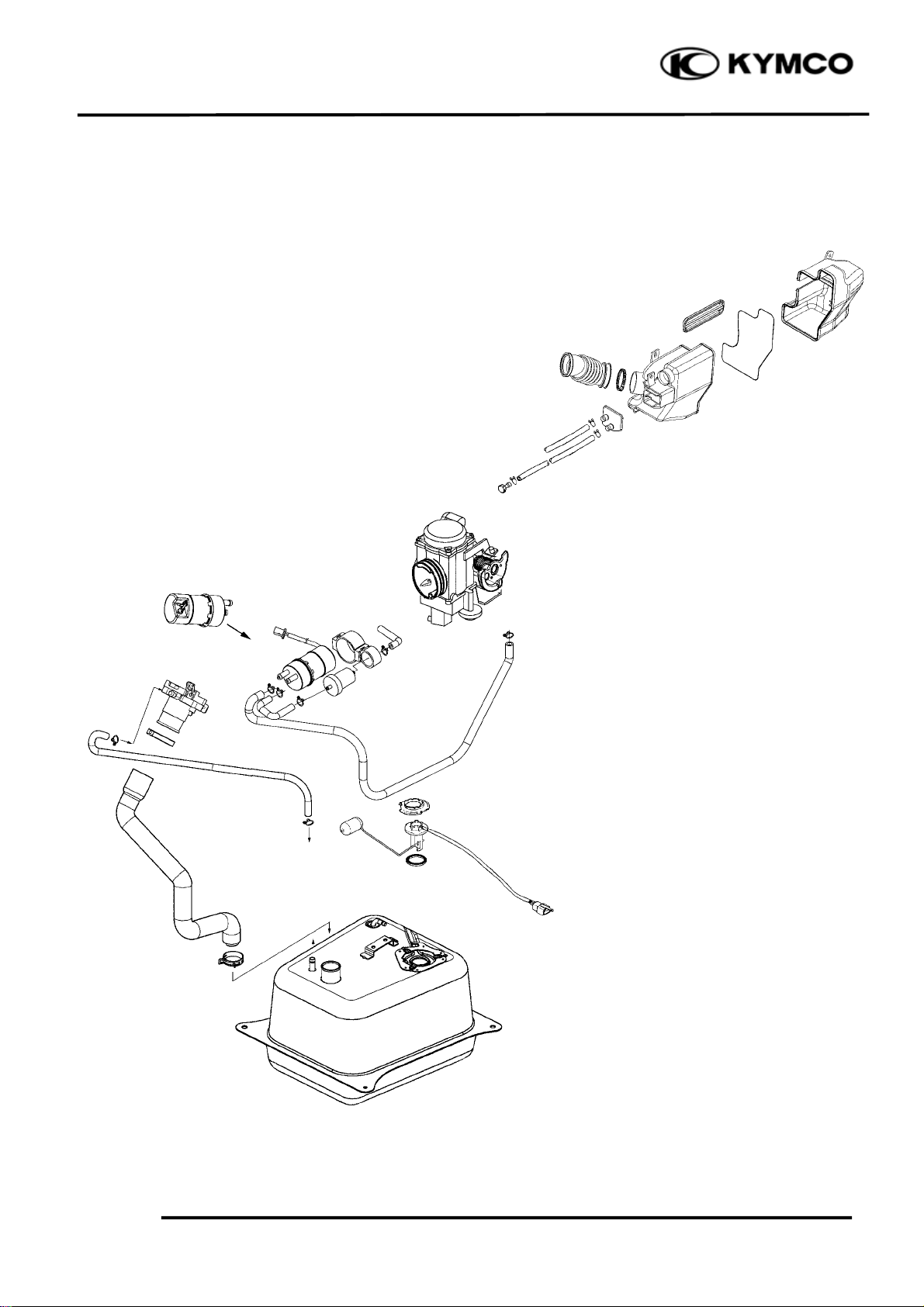
SCHEMATIC DRAWING
XCITING 500
5-1
Page 3
5. FUEL SYSTEM/FUEL PUMP
/FUEL TANK/CARBURETOR
XCITING 500
FUEL SYSTEM
The fuel pump is operated by an electromagnetic force and its electrical energy is supplied from the
battery. The fuel sent under pressure by the fuel pump flows into the float chamber when the float of
the carburetor has dropped and the needle valve is open. When the needle valve closes, the pressure of
the fuel in the hose connecting the carburetor and the fuel pump increases, and when the set pressure
is reached, the operation of the fuel pump is stopped by the fuel pressure to prevent excessive supply.
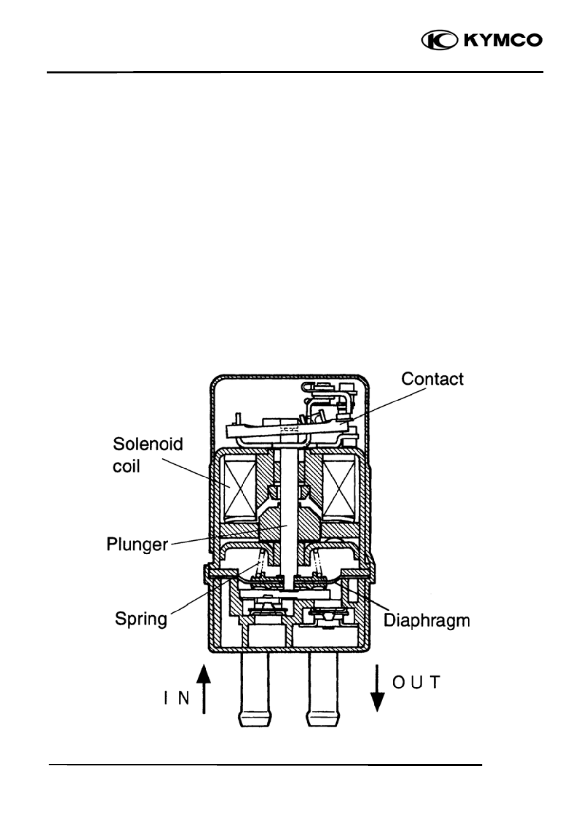
FUEL PUMP CONSTRUCTION
When voltage is applied between the fuel pump terminals, current flows into the solenoid coil which
then pulls up the plunger together with the diaphragm allowing fuel to be drawn into the pump. At this
time, the contact which is linked with the plunger opens and interrupts current causing the coil to be
de-energized. This allows the diaphragm to go down by the spring force, thereby pressurizing and
delivering fuel to the outlet. When the fuel pressure builds up and overcomes the spring force, the
plunger stops at pulled up position with the contact in open position.
5-2
Page 4
5. FUEL SYSTEM /FUEL PUMP
/FUEL TANK/CARBURETOR
XCITING 500
SERVICE INFORMATION
GENERAL INSTRUCTIONS
• When working with gasoline, keep away from sparks and flames.
• Note the locations of O-rings when disassembling and replace them with new ones during
assembly.
• Before float chamber disassembly, drain the residual gasoline from the float chamber.
• Do not try to disassemble the automatic choke.
• When assembling the vacuum chamber and air cut-off valve, be careful not to damage the
diaphragms.
• All cables, fuel lines and wires must be routed and secured at correct locations.
• When removing the fuel tank, keep sparks and flames away from the working area.
• When removing the fuel tank, the remaining fuel in the tank must be lower than 1/2 of the fuel
tank capacity to avoid gasoline overflowing.
• Fuel tank capacity: 12.8 liters
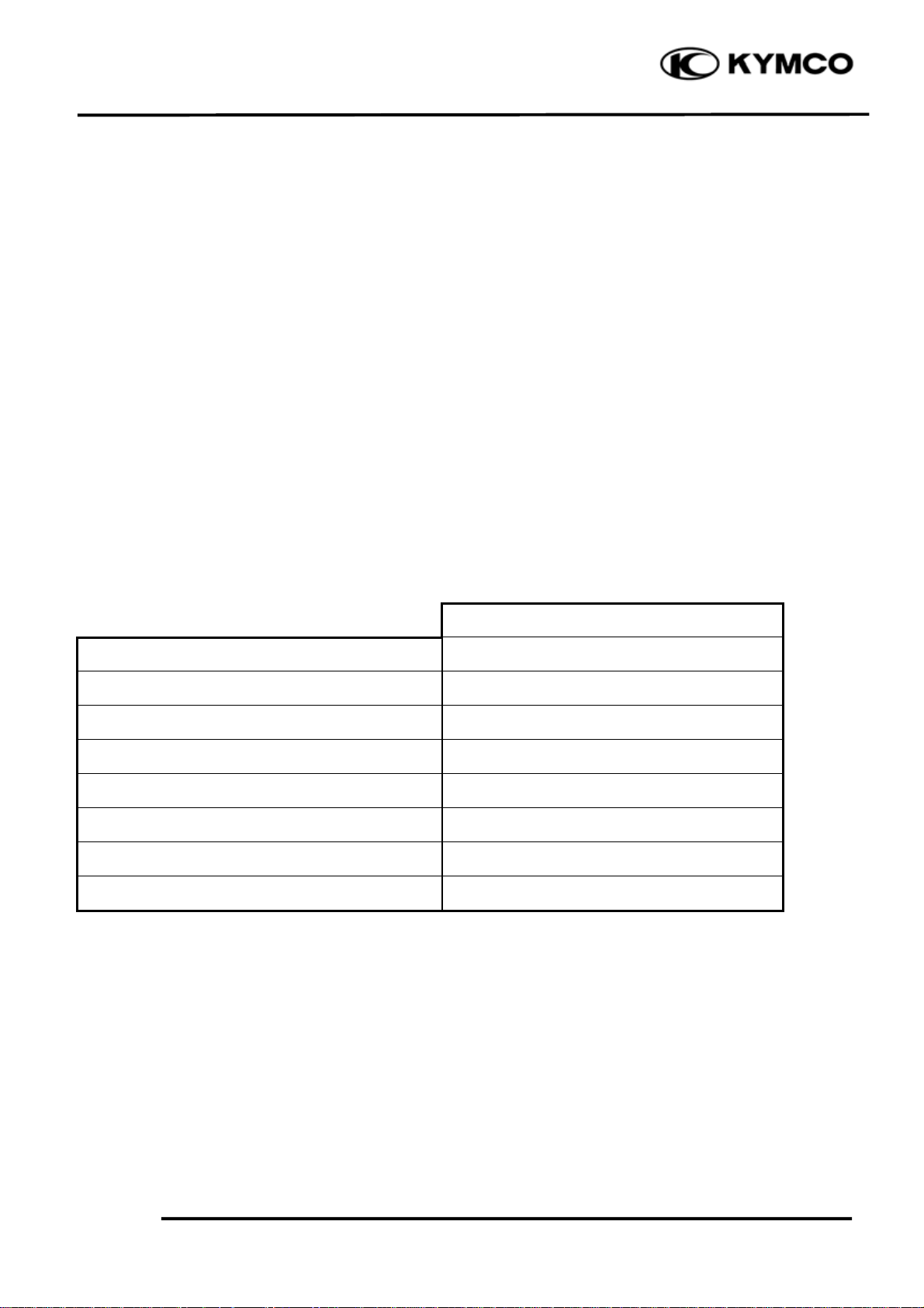
SPECIFICATIONS
XCITING 500
Type CVK
Carburetor identification number 15F8 SD8
Size of bore (mm) Ø36
Main jet #108
Slow jet #38
Idle speed 1400±100
Pilot screw opening 3½ ± ½ turns out
Fuel pump flow (at 12V) 370 ml (12.6 US oz, 13 lmp oz)/min
5-3
Page 5

5. FUEL SYSTEM/FUEL PUMP
/FUEL TANK/CARBURETOR
XCITING 500
TROUBLESHOOTING
Engine does not start Engine idles roughly, stalls or runs poorly
• No fuel in tank • Incorrect idle speed
• Restricted fuel line • Rich mixture
• Too much fuel getting to cylinder • Lean mixture
• Clogged air cleaner • Clogged air cleaner
• Contaminated fuel • Intake air leak
• Faulty fuel pump • Contaminated fuel
• Faulty air-cut off valve
• Damaged vacuum tube and connectors
• Damaged carburetor insulator
Throttle does not open fully, so engine stalls Rich mixture
• Damaged vacuum piston diaphragm • Automatic valve opens excessively
• Clogged diaphragm hole • Faulty float valve
• Float level too high
Lean mixture • Clogged air jets
• Clogged fuel jets • Automatic choke valve set plate installed in
• Clogged fuel tank cap breather hole
• Clogged fuel filter •Clogged air cleaner
• Bent, kinked or restricted fuel line
• Faulty float valve
• Float level too low
• Faulty fuel pump or insufficient output
the wrong groove
Engine is hard to start
• No fuel in tank
• Restricted fuel line
• Clogged fuel strainer
• Faulty fuel pump
• Broken or clogged vacuum tube
• Faulty or clogged charcoal canister
Lean mixture
• Clogged charcoal canister
• Bent, kinked or restricted fuel line
• Clogged fuel strainer
• Float level too low
5-4
Page 6

5. FUEL SYSTEM /FUEL PUMP
r
r
/FUEL TANK/CARBURETOR
CARBURETOR
REMOVAL
Remove the luggage box (page 2-3)
Loosen the air cleaner clamp screw.
Loosen the carburetor clamp screw.
Disconnect the vacuum hose from the
carburetor.
Pull the carburetor out from the air cleaner
and intake manifold.
.
Disconnect the fuel hose from the
carburetor.
Disconnect the carburetor heater connector.
XCITING 500
Carburetor Clamp Screw
Air Cleaner Clamp Screw Vacuum Hose
Fuel Hose
Disconnect the throttle cables.
Disconnect the automatic choke connector.
Disconnect the T.P.S connector.
Remove the carburetor.
5-5
Carburetor Heater Connecto
T.P.S Connector Throttle Cables
Automatic Choke Connecto
Page 7

5. FUEL SYSTEM/FUEL PUMP
r
/FUEL TANK/CARBURETOR
DISASSEMBLY
With the automatic choke cover removed,
remove the screw and automatic choke
assembly.
*
The automatic choke assembly is a nondisassemblable type
Remove the carburetor heater.
XCITING 500
Automatic Choke Assembly
Automatic Choke Cover Screw
Carburetor Heate
Remove the four screws and top cap.
Top Cap
Screws
5-6
Page 8

5. FUEL SYSTEM /FUEL PUMP
r
g
r
/FUEL TANK/CARBURETOR
Remove the spring , spring retainer, jet needle
and throttle valve.
Remove the two screws and casting
enrichment valve cover and then take out the
spring.
XCITING 500
Throttle Valve Spring Retaine
Jet Needle Sprin
Casting Enrichment Valve Cove
Remove the casting enrichment valve and Oring.
5-7
Screws
O-ring
Casting Enrichment Valve
Page 9

5. FUEL SYSTEM/FUEL PUMP
r
r
m
/FUEL TANK/CARBURETOR
Remove the three screws and accelerating
pump cover.
Remove the accelerating pump diaphragm
and O-ring.
XCITING 500
Screws
Accelerating Pump Cove
O-ring
Remove the four screws and float chamber.
Accelerating Pump Diaphrag
Float Chambe
Screws
5-8
Page 10

5. FUEL SYSTEM /FUEL PUMP
r
t
/FUEL TANK/CARBURETOR
Pull float pin outs, then remove the float and
float valve.
Remove the slow jet.
Remove the main jet.
XCITING 500
Float Float Valve
Float Pin
Main Jet Slow Je
Remove the needle jet holder.
5-9
Needle Jet Holde
Page 11

5. FUEL SYSTEM/FUEL PUMP
t
t
/FUEL TANK/CARBURETOR
Remove the needle jet.
XCITING 500
Needle Je
Pilot Screw
Remove the pilot screw, spring, washer and
O-ring.
*
Before pilot screw removal, slowly turn
the pilot screw clockwise and count the
number of turns until the screw is lightly
seated. Make a note of how many turns
were made so the screw can be reset
correctly.
FLOAT/FLOAT VALVE INSPECTION
Inspect the float for deformation or damage.
Floa
5-10
Page 12

5. FUEL SYSTEM /FUEL PUMP
t
t
/FUEL TANK/CARBURETOR
Check the float valve and valve seat for
foreign substance, clogging or damage.
Check the tip of the float valve, where it
contacts the valve seat, for stepped wear or
contamination.
Check the operation of the float valve.
CARBURETOR BODY/JETS
INSPECTION AND CLEANING
Check carburetor body and each jet for wear
or damage.
Clean all jets with a spray-type carburetor
cleaner and dry them using compressed air.
Clean all circuits of the carburetor
thoroughly-not just the perceived problem
area. Clean the circuits in the carburetor
body with a spray-type cleaner and allow
each circuit to soak, if necessary, to loosen
dirt and varnish. Blow the body dry using
compressed air.
XCITING 500
Main Jet/Needle Jet Holder/Needle Je
*
● Some carburetor cleaning chemicals ,
especially dip type soaking solutions,
are very corrosive and must be handled
carefully. Always follow the chemical
manufacturer’s instructions on proper
use, handling and storage.
● Do not use a wire to clean the jets or
passageways. A wire can damage the
jets and passageways. If the
components cannot be cleaned with a
spray cleaner it may be necessary to
use a dip-type cleaning solution and
allow them to soak. Always follow the
chemical manufacturer’s instructions
for proper use and cleaning of the
carburetor components.
After cleaning, reassemble the carburetor
with new seals.
5-11
Slow Je
Page 13

5. FUEL SYSTEM/FUEL PUMP
e
e
m
/FUEL TANK/CARBURETOR
PILOT SCREW INSPECTION
Remove the O-ring from the pilot screw.
Check the pilot screw for wear or damage.
*
The pilot screw is factory pre-set and
should not be removed unless the
carburetor is overhauled.
Damage to the pilot screw is tightened
against the seat.
THROTTLE VALVE/JET NEEDLE
INSPECTION
Check the throttle valve and jet needle for
scratches, wear or damage.
XCITING 500
Pilot Screw O-ring
Wash Spring
Throttle Valv
CASTING ENRICHMENT
VALVE/ACCELERATING PUMP
DIAPHRAGM INSPECTION
Check the casting enrichment
valve/accelerating pump diaphragm for
damage and clogging.
If any abnormal condition is found, wash the
part clean. If damage or clogging is found,
replace the part with a new one.
Jet Needl
Accelerating Pump Diaphrag
Casting Enrichment Valve
5-12
Page 14

5. FUEL SYSTEM /FUEL PUMP
e
r
/FUEL TANK/CARBURETOR
FLOAT LEVEL INSPECTION
Check the float level after checking the float
valve, valve seat and float.
Set the carburetor so that the float valve end
just contacts the float arm lip. Make sure the
float valve tip is securely in contact with the
valve seat.
Measure the float level with the float level
gauge.
Float level (A): 18.5mm (0.74 in)
The float level cannot be adjusted.
Replace the float assembly if the float level
is out of specification.
AUTO-BYSTARTER INSPECTION
Disconnect the connector.
Remove the automatic choke cover.
XCITING 500
(A)
Automatic Chok
Connect the positive (+) terminal of a 12 V
battery to Yellow lead and the negative (-)
terminal to the other Yellow lead.
Check that the automatic choke section is
heated in 5 minutes after the battery has
been connected.
To inspect the function, check for change of
temperature from the cold condition.
*
Do not attempt to disassemble the
automatic choke for the purpose of
checking temperature.
CARBURETOR HEATER INSPECTION
Disconnect the carburetor heater terminal
leads.
Carburetor Heate
5-13
Carburetor Heater Terminal Leads
Page 15

5. FUEL SYSTEM/FUEL PUMP
r
/FUEL TANK/CARBURETOR
Connect the positive (+) terminal of a 12 V
battery to the terminal of the carburetor
heater and the battery negative (-) terminal
to the terminal.
Check that the heater section is heated in 5
minutes after the battery has been connected.
REASSEMBLY
Carburetor reassembly can be performed in
the reverse order of disassembly. When
reassembling, carefully observe the
following instructions.
XCITING 500
Carburetor Heate
*
● Assemble the parts taking
consideration of their function.
● Replace O-rings and seals with new
ones.
Fit a new O-ring in to the float chamber
groove securely.
O-ring
5-14
Page 16

5. FUEL SYSTEM /FUEL PUMP
m
/FUEL TANK/CARBURETOR
Assemble the accelerating pump diaphragm
and new O-ring.
*
Install the accelerating pump diaphragm
with the small convex facing up.
Assemble the coasting enrichment valve and
new O-ring.
XCITING 500
O-ring Small Convex
Accelerating Pump Diaphrag
O-ring
Assemble the jet needle, spring retainer,
spring and throttle valve
Apply thermo-grease to the threads and
tighten the carburetor heater securely.
After cleaning, reinstall the pilot screw to
the original setting by turn the screw in until
it lightly seats, and then backing it out the
same number of turns counted during
disassembly.
*
Replace the O-ring with a new one.
Casting Enrichment Valve
After the assembly and installation on the
engine have been completed, perform the
following adjustment.
Throttle cable adjustment (page 3-5)
Idle speed adjustment (page 3-14)
INSTALLATION
Installation is in the reverse order of
removal.
5-15
Page 17

5. FUEL SYSTEM/FUEL PUMP
r
/FUEL TANK/CARBURETOR
FUEL FILTER/FUEL PUMP
FUEL FILTER INSPECTION
Visually check the fuel filter. If
accumulation of sediment or clogging is
found, replace the fuel filter with a new one.
Install the fuel filter with the arrow mark
facing forward.
FUEL PUMP INSPECTION
XCITING 500
Fuel Filter Arrow Mark
Fuel Pump Couple
Measure resistance between the terminals of
fuel pump lead wire coupler.
If the measurement is out of specification
replace the fuel pump.
Fuel pump resistance: 1-2.5Ω
As shown in the right illustration, connect
the battery to the fuel pump and measure the
pump discharge amount per minute using
kerosene.
Battery (+) to Black/Red
Battery (-) to Green
Discharge amount per minute:
370 ml (12.6 US oz, 13 lmp oz)
Fuel Pump
If the measurement is less than the standard
value, replace the fuel pump with a new one.
*
Do not use gasoline in this test as its is
highly combustible.
5-16
Page 18

5. FUEL SYSTEM /FUEL PUMP
r
t
t
/FUEL TANK/CARBURETOR
REMOVAL
Remove the floorboard (page 2-6)
Disconnect the fuel hoses.
Disconnect the fuel pump connector.
Remove the fuel pump and filter.
INSTALLATION
Installation is in the reverse order of
removal.
XCITING 500
Fuel Pump Connector Fuel Hoses
“Arrow” Mark Inlet Duc
*
● Install the fuel pump with the arrow
mark facing up.
● Connect the fuel inlet hose between the
inlet duct of the fuel pump and fuel
filter.
● Connect the fuel outlet hose between
the outlet duct of the fuel pump and
carburetor.
FUEL TANK
REMOVAL
Remove the floorboard (page
Remove the inner cover (page 2-14).
Remove the front lower cover (page 2-15).
Remove the fuel pump and fuel filter (page
5-17).
2-6
).
Outlet Duc
Remove the front heat insulation cover.
5-17
Heat Insulation Cove
Page 19

5. FUEL SYSTEM/FUEL PUMP
r
r
/FUEL TANK/CARBURETOR
Disconnect the fuel unit connector.
Remove the four nuts from the fuel tank.
Disconnect the ground wire connector.
Disconnect the fuel filler cap open cable.
XCITING 500
Fuel Unit Connecto
Nuts
Ground Wire Connecto
Remove the two nuts and left floorboard set
holder from the frame.
Remove the AICV control solenoid valve
from the left floorboard set holder.
Fuel Filler Cap Open Cable
ACIV Control Solenoid Valve
Nuts
5-18
Page 20

5. FUEL SYSTEM /FUEL PUMP
/FUEL TANK/CARBURETOR
Remove the fuel tank from the frame left
side.
XCITING 500
Fuel Tank
INSTALLATION
Installation is in the reverse order of
removal.
5-19
Fuel Tank
Fuel Tank
 Loading...