

Page 1

10. DRIVE AND DRIVEN PULLEY
XCITING 500
10
__________________________________________________________________________________
__________________________________________________________________________________
__________________________________________________________________________________
__________________________________________________________________________________
__________________________________________________________________________________
DRIVE AND DRIVEN PULLEY
__________________________________________________________________________________
SCHEMATIC DRAWING ------------------------------------------------- 10- 1
SERVICE INFORMATION------------------------------------------------ 10- 2
TROUBLESHOOTING----------------------------------------------------- 10- 2
LEFT CRANKCASE COVER--------------------------------------------- 10- 3
DRIVE PULLEY ------------------------------------------------------------ 10- 5
CLUTCH/DRIVEN PULLEY---------------------------------------------- 10-13
10
10-0
Page 2
10. DRIVE AND DRIVEN PULLEY
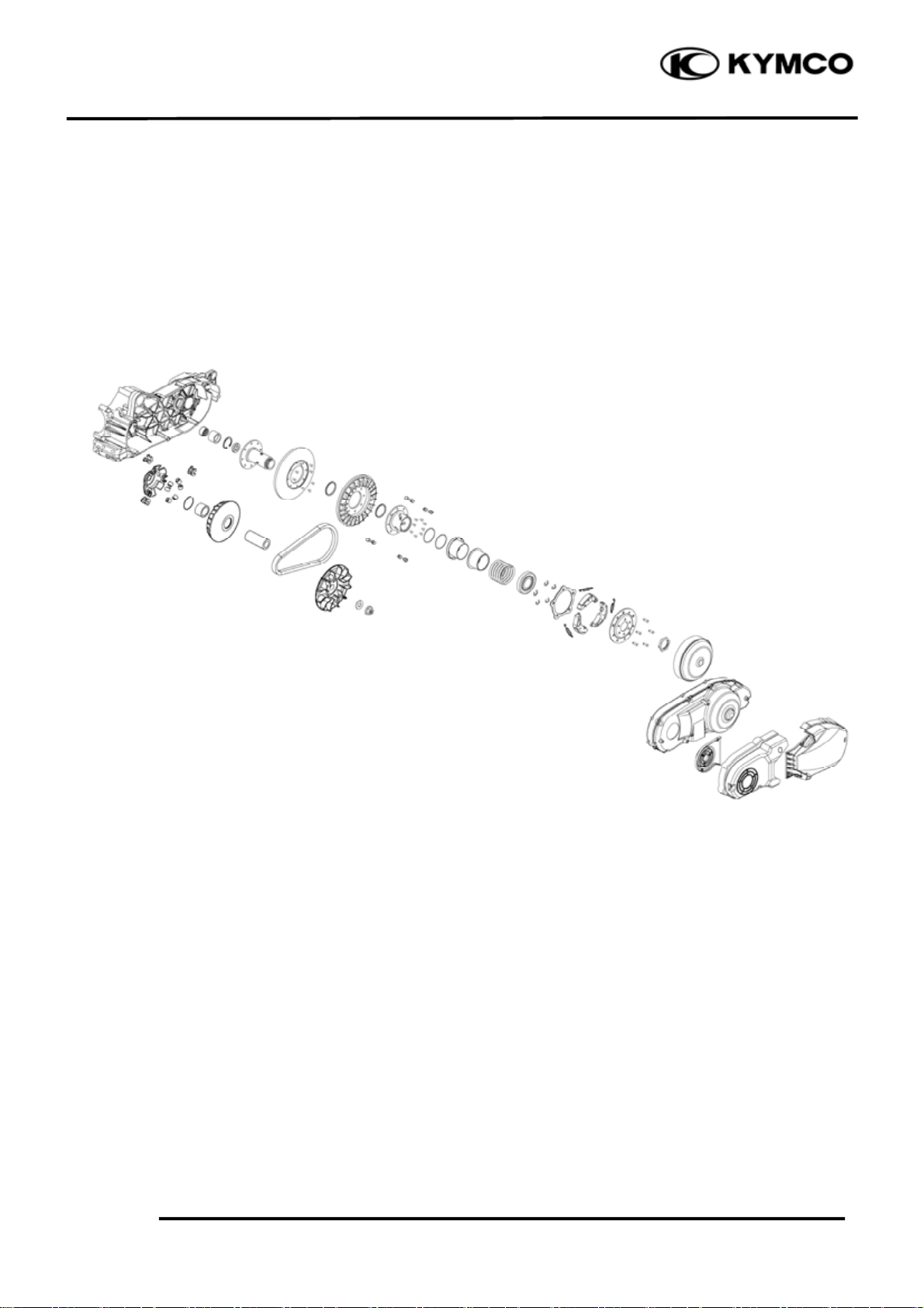
SCHEMATIC DRAWING
XCITING 500
10-1
Page 3
10. DRIVE AND DRIVEN PULLEY
m
d
XCITING 500
SERVICE INFORMATION
GENERAL INSTRUCTIONS
• The drive pulley, clutch and driven pulley can be serviced with the engine installed.
• Avoid getting grease and oil on the drive belt and pulley faces. Remove any oil or grease from
them to minimize the slipping of drive belt and drive pulley.
• Do not apply grease to the movable drive face and weight rollers.
SPECIFICATIONS Unit: mm (in)
Ite
Movable driven face bushing I.D.
Driven face collar O.D.
Drive belt width
Clutch lining thickness
Clutch outer I.D.
Drive pulley collar O.D.
Weight roller O.D.
TORQUE VALUES
Drive face nut 135 N•m (13.5 kgf•m, 97 lbf•ft)
Clutch outer nut 80 N•m (8 kgf•m, 58 lbf•ft)
Clutch drive plate nut 78 N•m (7.8 kgf•m, 56 lbf•ft)
SPECIAL TOOLS
Universal holder E017
Clutch spring compressor E053
Oil seal & bearing install E014
48 (1.89)~48.025 (1.891) 48.06 (1.892)
47.965 (1.888)~47.985 (1.889) 47.94 (1.887)
28.9 (1.156) 27.9 (1.116)
4 (0.16) 1 (0.04)
160 (6.3)~160.2 (6.31) 160.5 (6.32)
28.96 (1.158)~28.974 (1.159) 28.9 (1.156)
29.98 (1.1992)~30.08 (1.203) 29.5 (1.18)
Standar
Service Limit
TROUBLESHOOTING
Engine starts but motorcycle won‘t move Lack of power
• Worn drive belt • Worn drive belt
• Broken ramp plate • Weak driven face spring
• Worn or damaged clutch lining • Worn weight roller
• Broken driven face spring • Faulty driven face
Engine stalls or motorcycle creeps
• Broken clutch weight spring
10-2
Page 4
10. DRIVE AND DRIVEN PULLEY
Bolts
LEFT CRANKCASE COVER
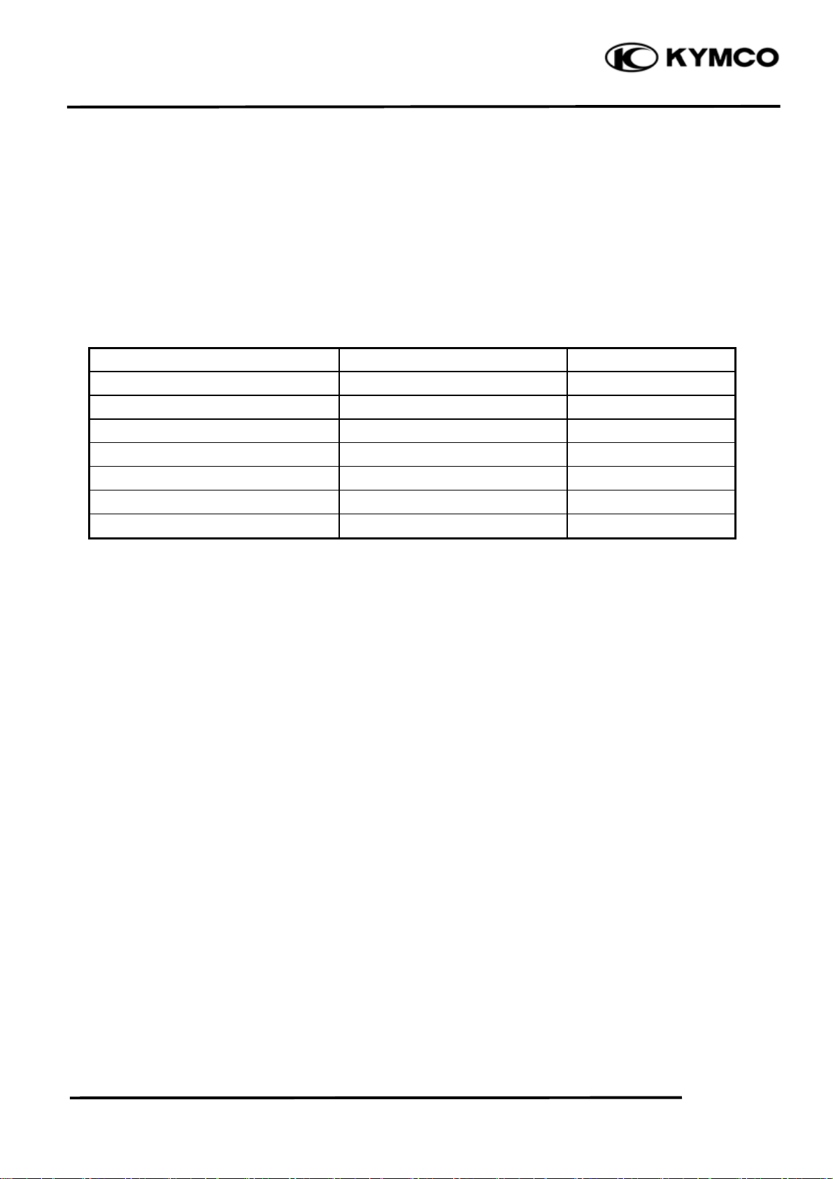
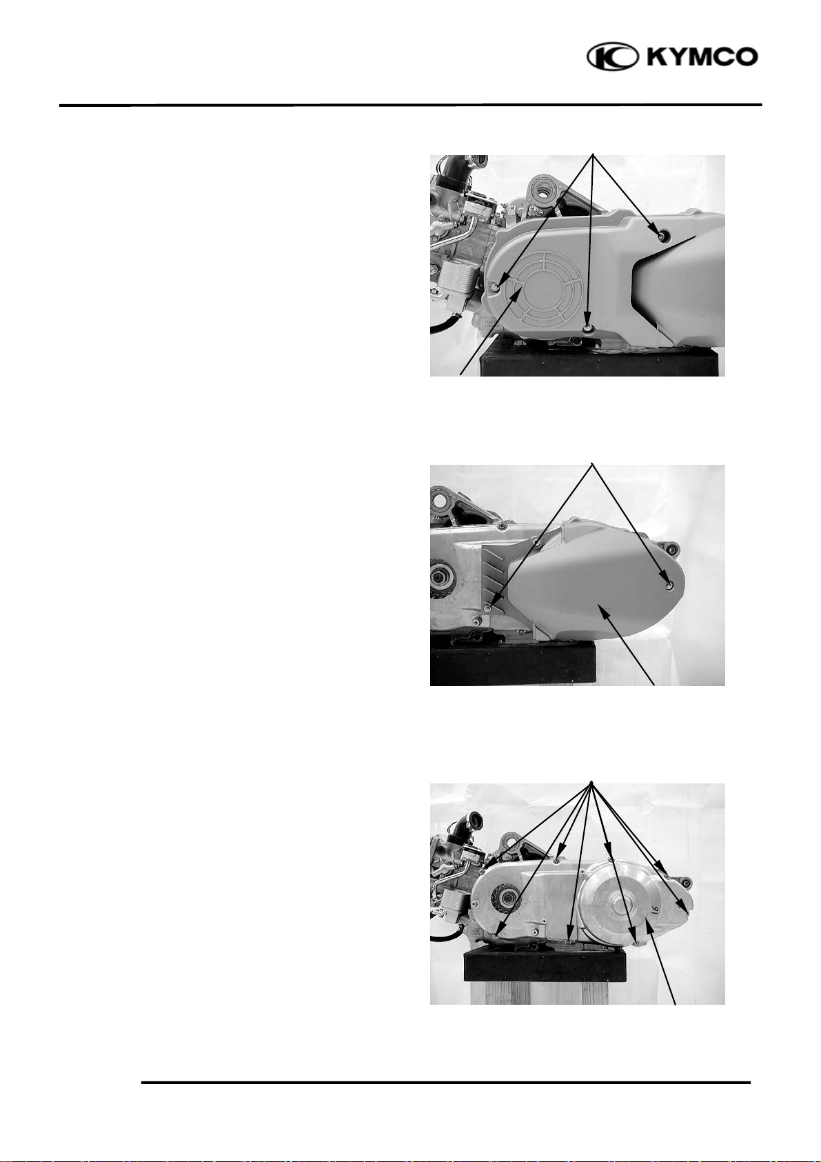
REMOVAL
Remove the left center body cover (page 2-5).
Remove the three bolts and the left front
cover.
Left Front Cover
.
XCITING 500
Remove the two bolts and left rear cover
Remove the eight bolts and left crankcase
cover.
Bolts
Left Rear Cover
Bolts
10-3
Crankcase
Page 5
10. DRIVE AND DRIVEN PULLEY
r
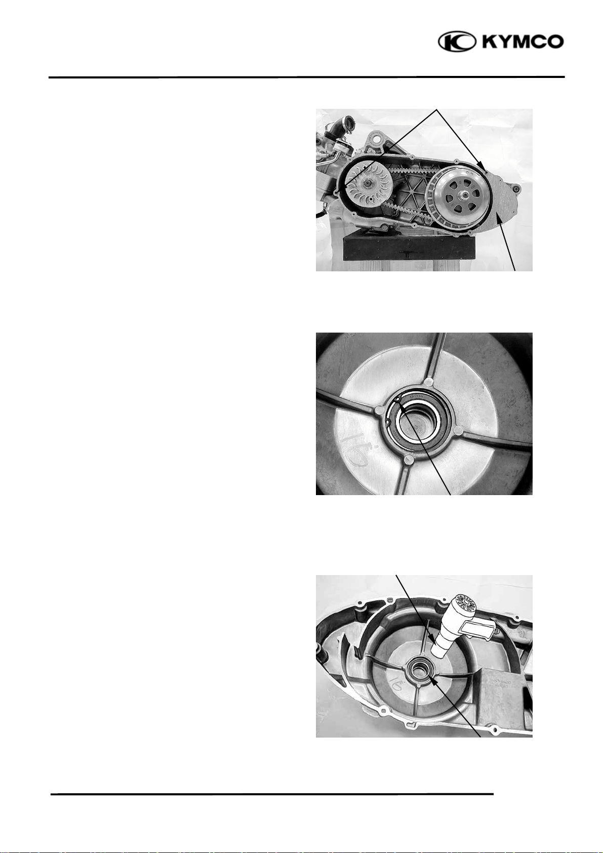
Dowel Pins
Remove the dowel pins and gasket.
Gasket
XCITING 500
DRIVESHAFT BEARING
REPLACEMENT
Remove the snap ring.
Heat the left crankcase cover around the
driveshaft bearing with industrial dryer.
Remove the driveshaft bearing from the left
crankcase cover.
Clip
Industrial Drye
Bearing
10-4
Page 6
10. DRIVE AND DRIVEN PULLEY
/
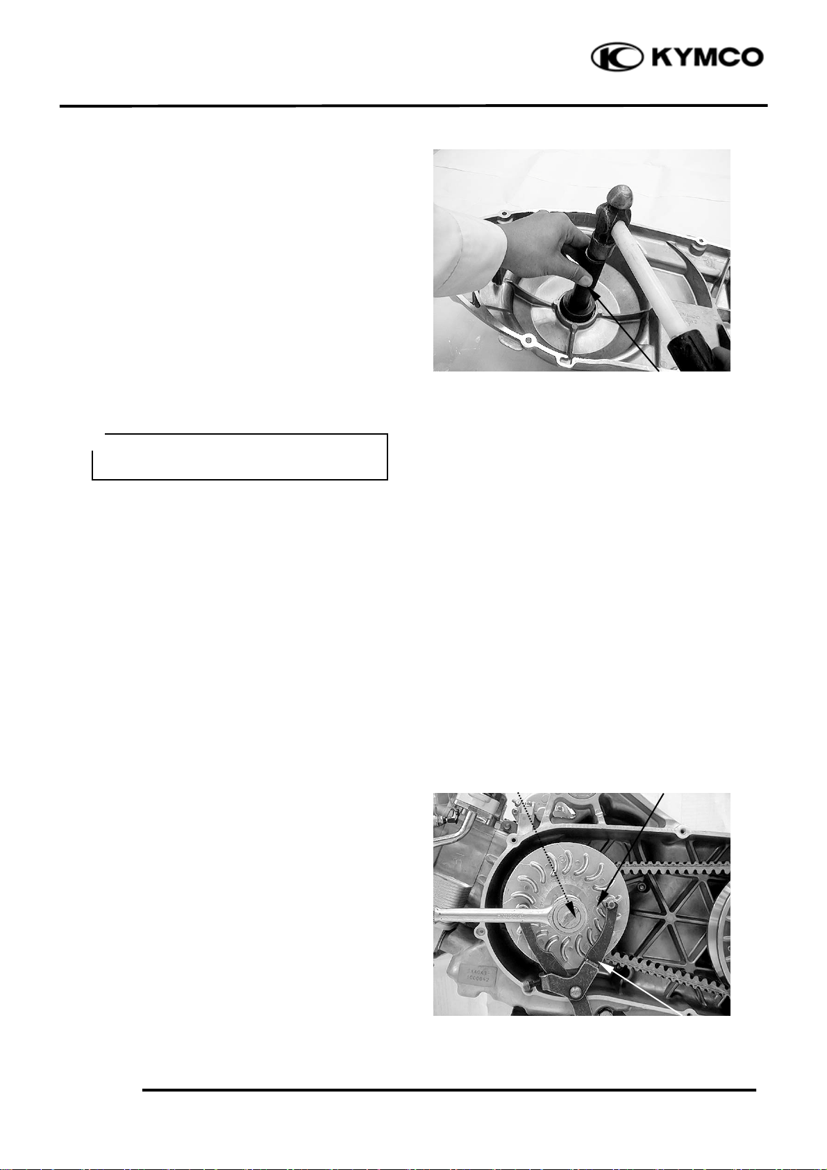
Install the new driveshaft bearing into the left
crankcase cover using a special tool.
Special tool:
Oil seal & bearing install E014
XCITING 500
INSTALLATION
Installation is in the reverse order of removal.
*
Clean the gasket on the left crankcase
before installation.
Bearing Install
DRIVE PULLEY
REMOVAL
Remove the left crankcase cover (page 10-3).
Hold the drive pulley face with the special
tool and loosen the drive pulley face nut.
Special tool:
Universal holder E017
Remove the nut, washer and drive pulley
face.
10-5
Nut
Universal Holder
Washer Drive Pulley Face
Page 7
10. DRIVE AND DRIVEN PULLEY
/
r
r
XCITING 500
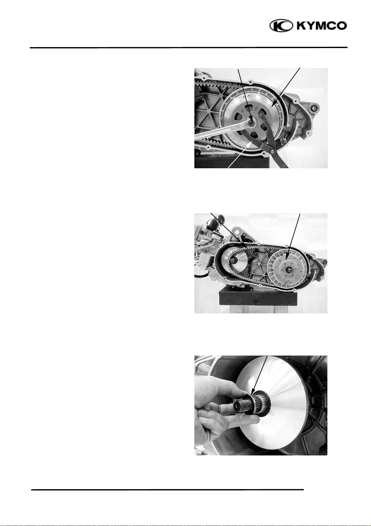
Hold the clutch outer with the special tool as
shown.
Special tool:
Universal holder E017
Remove the nut, collar and clutch outer.
Remove the clutch/driven pulley assembly
and drive belt.
Nut
Universal Holder
Drive Belt Clutch/Driven Pulley
Collar Clutch Oute
Remove the washer.
Washe
10-6
Page 8

10. DRIVE AND DRIVEN PULLEY
r
Drive Face Boss
Remove the movable drive face assembly
while holding the back of the face (ramp
plate).
Movable Drive Face
Washe
Remove the washer.
XCITING 500
DISASSEMBLY
Drive pulley
Remove the ramp plate and slide pieces.
10-7
Ramp Plate
Slide Pieces
Page 9

10. DRIVE AND DRIVEN PULLEY
Remove the weight rollers.
Weight Rollers
Drive Face Boss
Remove the drive face boss from the movable
drive face.
XCITING 500
INSPECTION
Movable Drive Face
Check the drive face boss for wear or
damage.
Measure the boss O.D..
Service limit: 28.9 mm (1.156 in)
Measure the face bushing I.D..
Service limit: 29.1 mm (1.164 in)
Slide Pieces
10-8
Page 10

10. DRIVE AND DRIVEN PULLEY
Weight Roller
Check each roller for wear or damage.
Measure the weight roller O.D..
Service limit: 29.5 mm (1.18 in)
Dust Seal
XCITING 500
Movable Drive Face
Check the dust seal for wear or damage.
ASSEMBLY
Clean any oil and grease from the pulley
faces and weight rollers.
Install the drive face boss into the movable
drive face.
Drive Face Boss
10-9
Page 11

10. DRIVE AND DRIVEN PULLEY
Weight Rollers
Install the weight rollers to the movable drive
face.
*
The direction of all weight rolls is the
same. The thin side is towards to
clockwise.
Thin Side
Ramp Plate
Install the slide pieces to ramp plate.
Install the ramp plate to the movable drive
face.
XCITING 500
INSTALLATION
Install the washer.
*
The inner indentation side on the washer
faces the left crankcase.
Slide Pieces
Inner Indentation Side
Washer
10-10
Page 12

10. DRIVE AND DRIVEN PULLEY
r
t
t
Washe
Clean any oil and grease from the pulley
faces and the drive belt.
Install the movable drive face assembly onto
the crankshaft while holding the ramp plate.
Install the washer.
Movable Drive Face Assembly
XCITING 500
Drive Bel
Install the drive belt and clutch/driven pulley
assembly.
*
Install the drive belt with the arrow mark
facing up and towards to clockwise.
Hold the clutch outer with the special tool as
shown.
Special tool:
Universal holder E017
Clutch/Driven Pulley Assembly
Clutch Outer Collar/Nu
Install the collar and nut.
Tighten the nut to the specified torque.
Torque: 80 N•m (8 kgf•m, 58 lbf•ft)
10-11
Universal Holder
Page 13

10. DRIVE AND DRIVEN PULLEY
/
XCITING 500
Install the drive pulley face and washer.
Apply oil to the drive pulley face nut threads
and seating surface and install the nut.
Hold the drive face with the special tool and
tighten the bolt to the specified torque.
Special tool:
Universal holder E017
Torque: 135 N•m (13.5 kgf•m, 97 lbf•ft)
Washer
Universal Holder
Nut Drive Pulley Face
10-12
Page 14

10. DRIVE AND DRIVEN PULLEY
/
/
r
XCITING 500
CLUTCH/DRIVEN PULLEY
REMOVAL
Remove the left crankcase cover (page 10-3).
Hold the drive pulley face with the special
tool and loosen the drive pulley face nut.
Special tool:
Universal holder E017
Remove the nut, washer and drive pulley
face.
Hold the clutch outer with the special tool as
shown.
Special tool:
Universal holder E017
Nut
Universal Holder
Nut
Washer Drive Pulley Face
Collar Clutch Oute
Remove the nut, collar and clutch outer.
Remove the clutch/driven pulley assembly
and drive belt.
Universal Holder
Drive Belt Clutch/Driven Pulley
10-13
Page 15

10. DRIVE AND DRIVEN PULLEY
r
r
XCITING 500
DISASSEMBLY
Clutch/Driven Pulley
Hold the clutch/driven pulley assembly with
the clutch spring compressor.
*
Be sure to use a clutch spring compresso
to avoid spring damage.
Special tool:
Clutch Spring Compressor E053
Set the tool in a vise and remove the clutch
drive plate nut.
.
Remove the spring compressor and
disassemble the following:
- Clutch assembly
- Driven face spring
- Driven pulley
Lock Nut Wrench
Clutch spring compresso
Driven Face Spring
Remove the washer
Remove the spring collar.
Remove the seal collar.
Washer
Spring Collar Seal Collar
10-14
Page 16

10. DRIVE AND DRIVEN PULLEY
XCITING 500
Remove the guide roller pins, guide rollers
and the movable driven face.
Remove the O-rings and oil seals from the
movable driven face.
Movable Driven Face
Guide Roller Pins/Guide Rollers
Oil Seals
Driven Face Bearing Replacement
Remove the driven face needle bearing.
Remove the snap ring, then remove the ball
bearing.
Apply grease to new ball bearing.
Install the ball bearing into the driven face.
Install the snap ring to groove in the driven
face securely.
10-15
O-rings
Snap Ring Needle Bearing
Ball Bearing
Page 17

10. DRIVE AND DRIVEN PULLEY
XCITING 500
Filling 25 g of grease to the driven face inner
surface.
Apply grease to new needle bearing.
Press the needle bearing into the driven.
INSPECTION
Clutch Outer
Check the clutch outer for wear or damage.
Measure the clutch outer I.D..
Needle Bearing
Grease
Service limit: 160.5 mm (6.32 in)
Clutch Shoe Lining
Check the clutch shoe for wear or damage.
Measure the thickness of each shoe.
Service limit: 1 mm (0.04 in)
10-16
Page 18

10. DRIVE AND DRIVEN PULLEY
Driven Face Spring
Measure the driven face spring free length.
Service limit: 100.7 mm (4.028 in)
XCITING 500
Driven Face
Check the driven face for scratches, scoring
or damage.
Measure the driven face boss O.D..
Service limit: 47.94 mm (1.887 in)
Movable Driven Face
Check the movable driven face for scratches,
scoring or damage.
Check the guide grooves for stepped wear or
damage.
Measure the movable driven face I.D..
Service limit: 48.06 mm (1.892 in)
10-17
Page 19

10. DRIVE AND DRIVEN PULLEY
Drive Belt
Check the drive belt for cracks, separation or
abnormal or excessive wear.
XCITING 500
Attach the suitable plates ad shown.
Measure the drive belt width.
Service limit: 27.9 mm (1.116 in)
Remove the clutch/driven pulley, then replace
the drive belt if necessary.
ASSEMBLY
Clean any oil from the drive belt sliding
surfaces on the driven face.
Apply grease to new oil seal lips and install
into the movable driven face.
Coat new O-rings with grease and install
them into the movable driven face grooves.
Oil Seals
O-rings
10-18
Page 20

10. DRIVE AND DRIVEN PULLEY
r
Install the movable driven face onto the
driven face.
Install the guide rollers and guide roller pins.
Filling 8 g of grease to each guide groove.
Driven Face Spring
Install the seal collar.
Install spring collar.
Install washer.
Install driven face spring.
XCITING 500
Grease
Install the drive belt into the driven pulley.
Squeeze and hold the drive belt your hand.
Set the clutch spring compressor over the
clutch/driven pulley assembly and hold the
spring compressor in a vice.
Special tool:
Clutch Spring Compressor E053
Compress the driven face spring.
Install and tighten the clutch drive plate nut
to the specified torque.
Torque: 78 N•m (7.8 kgf•m, 56 lbf•ft)
Washer
Lock Nut Wrench
Clutch spring compresso
10-19
Page 21

10. DRIVE AND DRIVEN PULLEY
t
/
r
/
Drive Bel
*
Install the drive belt with the arrow mark
facing up and towards to clockwise.
Install the drive belt and clutch/driven pulley
assembly.
XCITING 500
Clutch/Driven Pulley Assembly
Hold the clutch outer with the special tool as
shown.
Special tool:
Universal holder E017
Install the collar and nut.
Tighten the nut to the specified torque.
Torque: 80 N•m (8 kgf•m, 58 lbf•ft)
Install the drive pulley face and washer.
Apply oil to the drive pulley face nut threads
and seating surface and install the nut.
Nut
Universal Holder
Washer
Collar Clutch Oute
Nut Drive Pulley Face
Hold the drive face with the special tool and
tighten the bolt to the specified torque.
Special tool:
Universal holder E017
Torque: 135 N•m (13.5 kgf•m, 97 lbf•ft)
Universal Holder
10-20
 Loading...