

Page 1

9. CYLINDER/PISTON
XCITING 500
9
__________________________________________________________________________________
__________________________________________________________________________________
__________________________________________________________________________________
__________________________________________________________________________________
__________________________________________________________________________________
CYLINDER/PISTON
__________________________________________________________________________________
SCHEMATIC DRAWING ------------------------------------------------- 9-1
SERVICE INFORMATION------------------------------------------------ 9-2
TROUBLESHOOTING----------------------------------------------------- 9-2
CYLINDER/PISTON REMOVAL---------------------------------------- 9-3
CYLINDER/PISTON INSTALLATION--------------------------------- 9-7
9
9-0
Page 2
9. CYLINDER/PISTON
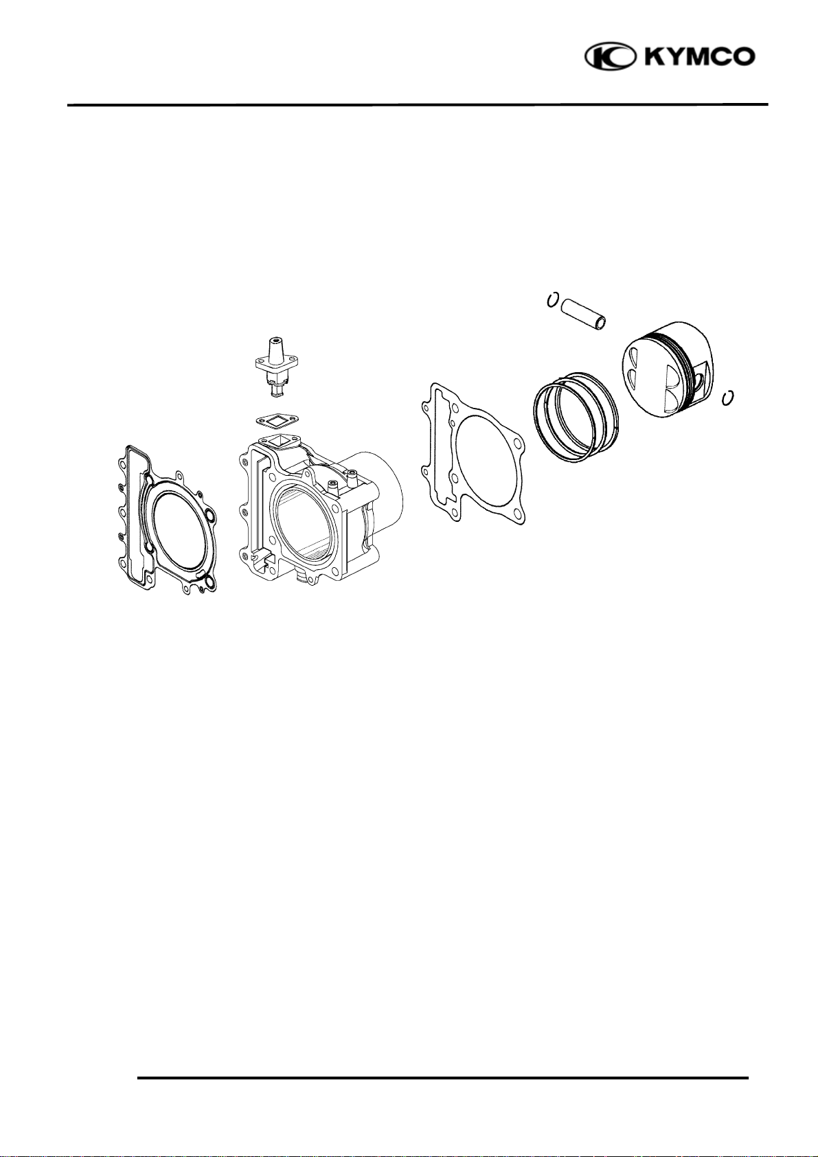
SCHEMATIC DRAWING
XCITING 500
9-1
Page 3
9. CYLINDER/PISTON
m
d
r
XCITING 500
SERVICE INFORMATION
GENERAL INSTRUCTIONS
• The cylinder and piston can be serviced with the engine installed in the frame.
• When installing the cylinder, use a new cylinder gasket and make sure that the dowel pins are
correctly installed.
• After disassembly, clean the removed parts and dry them with compressed air before inspection.
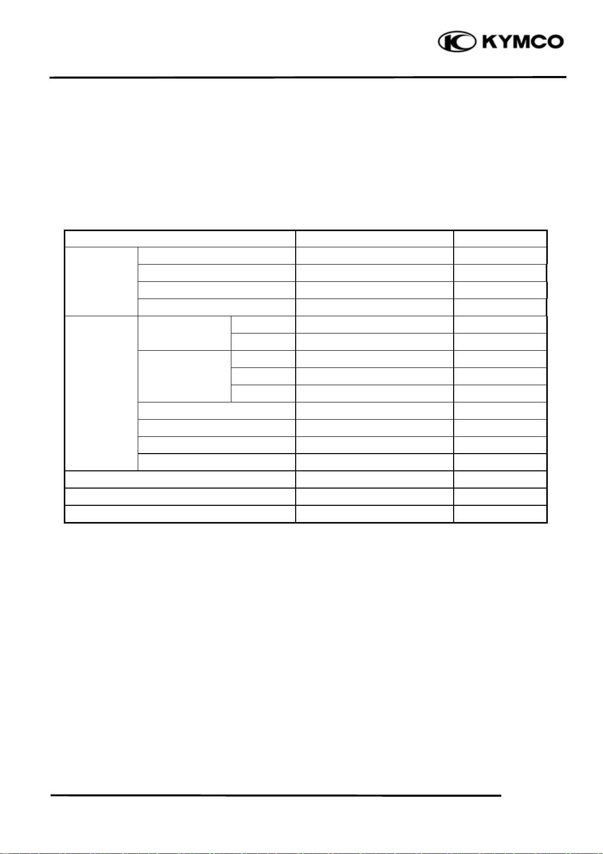
SPECIFICATIONS Unit: mm (in)
Ite
I.D. 92.005 (3.6802)~92.015 (3.6806) 92.1 (3.684)
Cylinde
Piston, Ring end gap Second
piston ring Oil side rail
. Piston-to-cylinder clearance
Piston pin O.D
Piston-to-piston pin clearance
Connecting rod small end I.D. bore
Warpage
Cylindricity
True roundness
Ring-to-groove top
clearance
Piston O.D.
Piston O.D. measuring position
Piston pin hole I.D.
Second
top
Standar
0.01 (0.0004)
0.01 (0.0004)
0.01 (0.0004)
0.03 (0.0012)~0.065 (0.0026) 0.08 (0.003)
0.015 (0.0006)~0.05 (0.002) 0.065 (0.0026)
0.15 (0.006)~0.3 (0.012) 0.5 (0.02)
0.03 (0.012)~0.45 (0.018) 0.65 (0.026)
0.2 (0.008)~0.7 (0.028)
91.96 (3.6784)~91.98 (3.6793) 91.9 (3.676)
10 mm from bottom of skirt -
0.01 (0.0004)~0.045 (0.0018) 0.1 (0.004)
22.002 (0.8801)~22.008 (0.8803) 22.04 (0.8826)
21.994 (0.8798)~22 ( 0 . 8 8 ) 21.96 (0.8784)
0.002 (0.0001)~0.014 (0.0006) 0.02 (0.001)
22.016 (0.8806)~22.034 (0.8814) 22.06 (0.8824)
Service Limit
0.05 (0.002)
0.1 (0.004)
0.1 (0.004)
1 (0.04)
TROUBLESHOOTING
• When hard starting or poor performance at low speed occurs, check the crankcase breather for
white smoke. If white smoke is found, it means that the piston rings are worn, stuck or broken.
Compression too low or uneven
compression Excessive smoke from exhaust muffler
• Worn or damaged cylinder and piston rings • Worn or damaged piston rings
• Worn, stuck or broken piston rings • Worn or damaged cylinder and piston
Compression too high Abnormal noisy piston
• Excessive carbon build-up in combustion • Worn cylinder, piston and piston rings
chamber or on piston head • Worn piston pin hole and piston pin
• Incorrectly installed piston
9-2
Page 4

9. CYLINDER/PISTON
XCITING 500
CYLINDER/PISTON
Remove the cylinder head (page 8-11).
Take the block pin out.
Remove the water hose from the cylinder.
Remove the two cylinder bolts.
Remove the cylinder and gasket.
Remove the dowel pins
REMOVAL
Bolts Cylinder/Gasket Block Pin
Water Hose
Dowel Pins
Remove the piston pin clip.
*
Place a clean shop towel in the crankcase
to keep the piston pin clip from falling
into the crankcase.
Press the piston pin out of the piston and
remove the piston.
9-3
Dowel Pins
Piston Pin Clip
Piston Piston Pin
Page 5

9. CYLINDER/PISTON
Spread each piston ring and remove it by
lifting up at a point opposite the gap
*
Do not damage the piston ring by
spreading the ends too far.
Clean carbon deposits from the piston ring
grooves.
INSPECTION
Piston ring
Inspect the piston rings for movement by
rotating the rings. The rings should be able to
move in their grooves without catching.
XCITING 500
Push the ring until the outer surface of the
piston ring is nearly flush with the piston and
measure the ring-to-groove clearance.
Service Limits: Top: 0.08 mm (0.003 in)
2nd: 0.065 mm (0.0026 in)
Insert each piston ring into the bottom of the
cylinder squarely.
*
Use the piston head to push each piston
ring into the cylinder.
Measure the piston ring end gap.
Service Limit:
Top: 0.5 mm (0.02 in)
2nd: 0.65 mm (0.026 in)
Oil ring: 1 mm (0.04 in)
9-4
Page 6

9. CYLINDER/PISTON
m
m
Piston/Piston pin
Measure the piston O.D. at the point 10 mm
from the bottom and 90° to the piston pin
hole.
Service Limit: 91.9 mm (3.676 in)
Calculate the cylinder-to-piston clearance
(cylinder I.D.: page 9-6)
Measure the piston pin hole. Take the
maximum reading to determine the I.D..
XCITING 500
10 m
10 m
Service Limit: 22.04 mm (0.8826 in)
Measure the piston pin O.D. at piston and
connecting rod sliding areas.
Service Limit: 21.96 mm (0.8784 in)
Measure the piston-to-piston pin clearance.
Service Limit: 0.002 mm (0.0001 in)
9-5
Page 7

9. CYLINDER/PISTON
Cylinder
Check the cylinder for warpage with a
straight edge and feeler gauge in the
directions shown.
Service Limit: 0.05 mm (0.002 in)
XCITING 500
Check the cylinder wall for wear or damage.
Measure and record the cylinder I.D. at three
levels in an X and Y axis. Take the maximum
reading to determine the cylinder wear.
Service Limit: 92.1 mm (3.684 in)
Calculate the piston-to-cylinder clearance.
Take a maximum reading to determine the
clearance. Refer to page 9-5 for measurement
of the piston O.D..
Service Limit: 0.1 mm (0.004 in)
Calculate the taper and out-of-round at three
levels in an X and Y axis. Take the maximum
reading to determine them.
Service Limit:
Taper: 0.1 mm (0.004 in)
Out-of-round: 0. 1 mm (0.004 in)
TOP
MIDDLE
BOTTOM
9-6
Page 8

9. CYLINDER/PISTON
d
Measure the connecting rod small end I.D..
Service Limit: 22.06 mm (0.8824 in)
Calculate the connecting rod-to-piston pin
clearance.
Service Limit: 0.06 mm (0.002 in)
XCITING 500
CYLINDER/PISTON
INSTALLATION
PISTON RING INSTALLATION
Carefully install the piston rings into the
piston ring grooves with the markings facing
up.
*
Be careful not to damage the piston an
rings.
Do not confuse the top and second rings.
To install the oil ring, install the oil ring,
then install the side rails.
Stagger the piston ring end gaps 120° degrees
apart from each other.
Stagger the side rail end gaps as shown.
9-7
Page 9

9. CYLINDER/PISTON
XCITING 500
CYLINDER/PISTON INSTALLATION
Clean any gasket material from the cylinder
mating surfaces of the crankcase and oil
passage.
Apply engine oil to the piston pin.
Apply engine oil to the connecting rod small
end and piston pin hole.
Install the piston with the “IN” mark face
intake side and piston pin.
Place a clean shop towel over the crankcase
prevent the clip from falling into the
crankcase.
Piston “IN” Mark
Piston Pin
Piston Pin Clip
Install the new pin clip.
*
Make sure that the piston pin clips are
seated securely.
Do not align the piston pin clip end gap
with the piston cut-out
Install the dowel pins.
Piston Piston Pin
Dowel Pins
Dowel Pins
9-8
Page 10

9. CYLINDER/PISTON
Install the gasket.
Apply engine oil to the cylinder wall, piston
and piston ring outer surfaces.
Pass the cam chain through the cylinder and
install the cylinder over the piston.
*
Be careful not to damage the piston rings
and cylinder walls.
Install and tighten the two cylinder bolts to
specified torque.
Torque: 10 N•m (1 kgf•m, 7 lbf•ft)
Install the block pin.
Connect the water hose.
XCITING 500
Bolts Cylinder/Gasket Block Pin
Water Hose
9-9
 Loading...