

Page 1

12. A.C. GENERATOR/STARTER CLUTCH
XCITING 500
12
__________________________________________________________________________________
__________________________________________________________________________________
__________________________________________________________________________________
__________________________________________________________________________________
__________________________________________________________________________________
12
A.C. GENERATOR/STARTER CLUTCH
__________________________________________________________________________________
SCHEMATIC DRAWING ------------------------------------------------- 12-1
SERVICE INFORMATION------------------------------------------------ 12-2
TROUBLESHOOTING----------------------------------------------------- 12-2
ALTERANTOR STATOR-------------------------------------------------- 12-3
FLYWHEEL/STARTER CLUTCH--------------------------------------- 12-4
12-0
Page 2
12. A.C. GENERATOR/STARTER CLUTCH
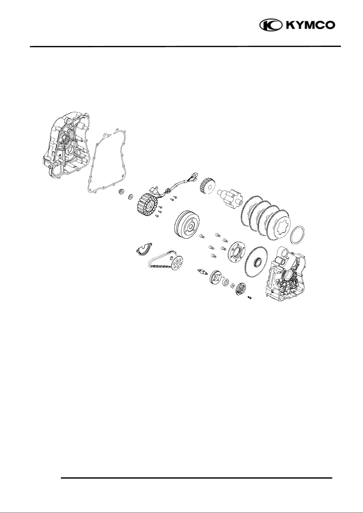
SCHEMATIC DRAWING
XCITING 500
12-1
Page 3

12. A.C. GENERATOR/STARTER CLUTCH
XCITING 500
SERVICE INFORMATION
GENERAL INSTRUCTIONS
• All servicing operations and inspections in this section can be made with the engine installed.
• Drain the coolant before removing the right crankcase cover.
• Be careful not to drain the coolant when the engine temperature is high. (Perform this operation
when the engine is cold.)
• Drain the coolant into a clean container.
• Drain the engine oil into a clean container before removing the right crankcase cover.
• When the right crankcase cover is installed, fill with the recommended engine oil and coolant.
Then, bleed air from the water jacket.
• Refer to section 17 for alternator inspection, and to section 18 for ignition pulse generator
inspection.
SPECIFICATIONS Unit: mm (in)
Item Standard Service Limit
Starter driven gear I.D. 27.026 (1.081)~27.045 (1.0818) 27.1 (1.084)
Starter driven gear O.D. 45.66 (1.8264)~45.673 (1.8292) 45.6 (1.824)
SPECIAL TOOLS
Flywheel puller E054
Flywheel holder E021
TORQUE VALUES
Flywheel nut: 55 N•m (5.5 kgf•m, 40 lbf•ft)
TROUBLESHOOTING
Starter motor turns, but engine does not turn
• Faulty starter clutch
• Damaged starter reduction gear
12-2
Page 4

12. A.C. GENERATOR/STARTER CLUTCH
r
t
t
Right Crankcase Cove
ALTERNATOR STATOR
REMOVAL
Remove the right center body cover (page 2-
5).
Remove the exhaust muffler (page 2-15).
Remove water pump (page 6-10).
Remove the fifteen bolts and right crankcase
cover, dowel pins and gasket.
XCITING 500
Remove the two pulse coil mount bolts.
Remove the three stator mount bolts,
grommet and the stator from the right
crankcase cover.
INSTALLATION
Install the stator and tighten the stator mount
bolts to the specified torque.
Torque: 12 N•m (1.2 kgf•m, 9 lbf•ft)
Apply sealant to the grommet seating surface
and install it to the cover groove properly.
Install the pulse coil and tighten mount bolts
to the specified torque.
Torque: 12 N•m (1.2 kgf•m, 9 lbf•ft)
Clean the mating surfaces of the right
crankcase and cover.
Stator Bolts Gromme
Bolts Pulse Coil
Dowel Pins Gaske
Install the dowel pins and gasket.
Install the right crankcase cover and tighten
the bolts in a crisscross pattern in 2 or 3 steps.
12-3
Page 5

12. A.C. GENERATOR/STARTER CLUTCH
r
r
Flywheel Holder Nut/Washe
FLYWHEEL/STARTER CLUTCH
REMOVAL
Remove the right crankcase cover (page 12-
3).
Hold the flywheel with the special tool and
loosen the flywheel nut.
Special tool:
Flywheel holder E021
Remove the flywheel nut and washer.
Flywheel Pulle
Remove the flywheel/starter driven gear
assembly using the special tool.
XCITING 500
Special tool:
Flywheel puller E054
Remove the woodruff key.
Woodruff Key
12-4
Page 6

12. A.C. GENERATOR/STARTER CLUTCH
r
r
Reduction Gea
Remove the reduction gear.
Driven gea
XCITING 500
INSPECTION
Check the operation of the sprag clutch by
turning the driven gear.
You should be able to turn the driven gear
clockwise smoothly, but the gear should not
turn counterclockwise.
Remove the starter driven gear by turning the
driven gear.
Check the starter driven gear teeth for wear or
damage.
Measure the starter driven gear boss O.D..
Flywheel
Service limit: 45.6 mm (1.824 in)
Measure the starter driven gear bushing I.D..
Service limit: 27.1 mm (1.084 in)
12-5
Page 7

12. A.C. GENERATOR/STARTER CLUTCH
r
r
r
XCITING 500
Check the starter reduction gear teeth and
shaft for wear or damage.
Apply oil to the starter reduction gear.
Install the starter reduction gear to the right
crankcase.
Reduction Gea
Reduction Gea
Apply molybdenum oil solution to the
starter driven gear bushing.
Install the starter driven gear by turning the
driven gear clockwise.
Driven gea
Flywheel
12-6
Page 8

12. A.C. GENERATOR/STARTER CLUTCH
r
Clean any oil from tapered portion of the
crankshaft.
Install the woodruff key in the crankshaft
key groove.
Woodruff Key
XCITING 500
Clean any oil from the tappered portion of
the flywheel I.D..
Install the flywheel/driven gear onto the
crankshaft, aligning the key way with
woodruff key.
Apply oil to the washer and flywheel nut
threads and seating surface.
Install the washer and flywheel nut to the
crankshaft.
Hold the flywheel with the special tool and
tighten the flywheel nut to the specified
torque.
Special tool:
Flywheel holder E021
Torque: 55 N•m (5.5 kgf•m, 40 lbf•ft)
Flywheel Holder Nut/Washe
12-7
 Loading...