

Page 1

8. CYLINDER HEAD/VALVES
XCITING 500
8 .
__________________________________________________________________________________
__________________________________________________________________________________
__________________________________________________________________________________
__________________________________________________________________________________
__________________________________________________________________________________
CYLINDER HEAD/VALVES
__________________________________________________________________________________
SCHEMATIC DRAWING ------------------------------------------------- 8- 1
SERVICE INFORMATION------------------------------------------------ 8- 2
TROUBLESHOOTING----------------------------------------------------- 8- 3
CYLINDER COMPRESSION TEST ------------------------------------- 8- 4
CYLINDER HEAD COVER----------------------------------------------- 8- 5
CAMSHAFT REMOVAL -------------------------------------------------- 8- 6
ROCKER ARM REMOVAL----------------------------------------------- 8-10
CYLINDER HEAD REMOVAL ------------------------------------------ 8-11
CYLINDER HEAD INSTALLATION ----------------------------------- 8-16
ROCKER ARM INSTALLATION---------------------------------------- 8-18
CAMSHAFT INSTALLATION ------------------------------------------- 8-19
8
CYLINDER HEAD COVER INSTALLATION ------------------------ 8-23
8-0
Page 2
8. CYLINDER HEAD/VALVES
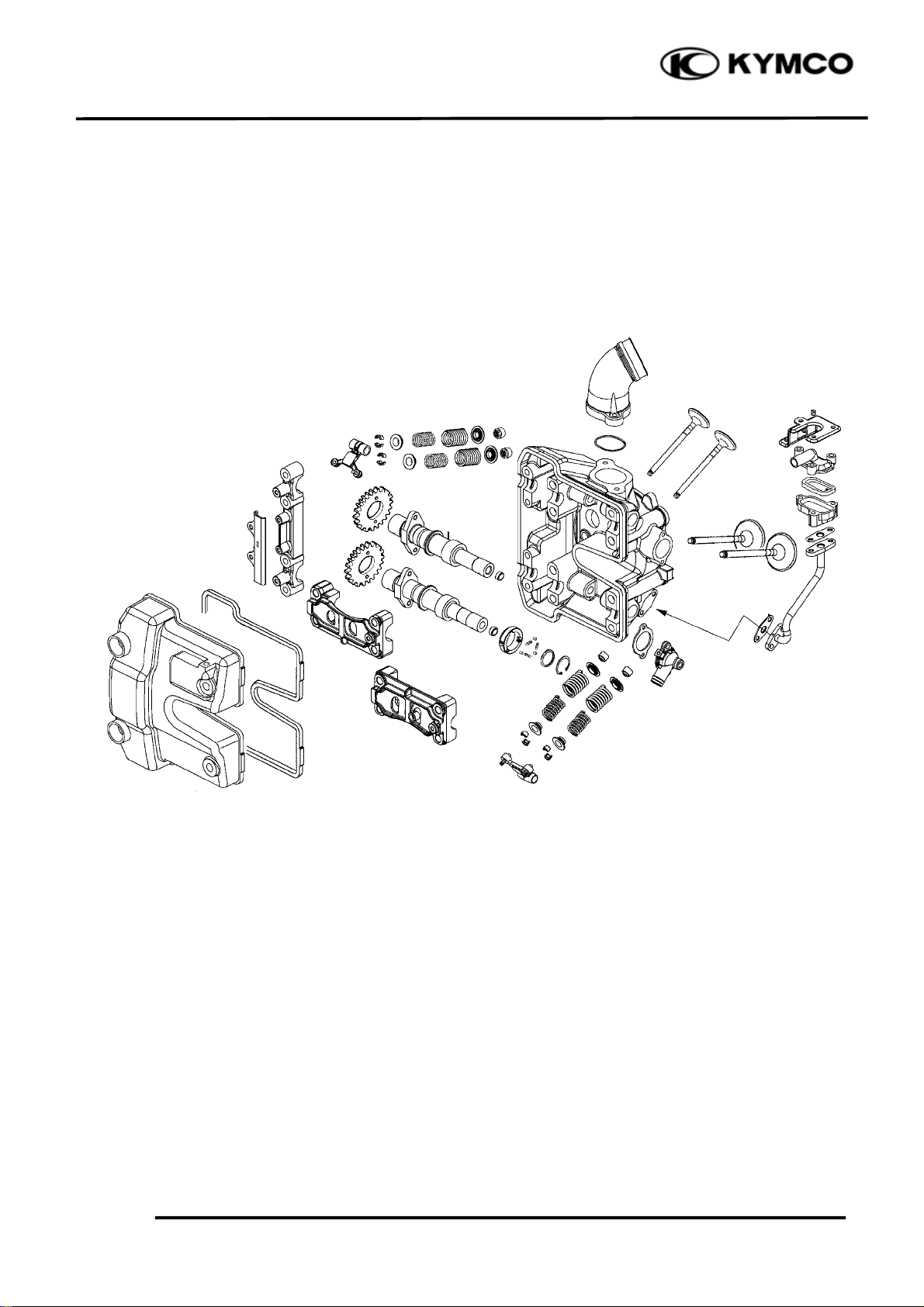
SCHEMATIC DRAWING
XCITING 500
8-1
Page 3
8. CYLINDER HEAD/VALVES
m
d
)
⎯
)
⎯
⎯
)
)
)
)
)
)
)
)
)
)
)
)
)
)
)
)
)
)
)
)
)
)
)
)
(
)
XCITING 500
SERVICE INFORMATION
GENERAL INSTRUCTIONS
• The cylinder head can be serviced with the engine installed in the frame. Coolant in the radiator
and water jacket must be drained first.
• When assembling, apply molybdenum disulfide grease or engine oil to the valve guide movable
parts and valve arm sliding surfaces for initial lubrication.
• The valve rocker arms are lubricated by engine oil through the cylinder head engine oil passages.
Clean and unclog the oil passages before assembling the cylinder head.
• After disassembly, clean the removed parts and dry them with compressed air before inspection.
• After removal, mark and arrange the removed parts in order. When assembling, install them in
the reverse order of removal.
SPECIFICATIONS
Ite
Valve clearance (cold)
Cylinder head compression pressure 13 kg/cm2 (185 psi, 1300 kPa) ⎯
Cylinder head warpage
Camshaft cam height
Valve rocker arm I.D.
Valve rocker arm shaft IN 9.975 (0.399)~9.99 (0.3996
O.D. EX 9.975 (0.399)~9.99 (0.3996
Valve stem O.D.
Valve guide I.D.
Valve stem-to-guide IN 0.01 (0.004)~0.037 (0.0015
clearance EX 0.03 (0.0012)~0.057 (0.0023
TORQUE VALUES
Cylinder head bolt (13) 13 N•m (1.3 kgf•m, 9 lbf•ft) Apply engine oil to threads
Cylinder head bolt (1 – 4) 48 N•m (4.8 kgf•m, 35 lbf•ft) Apply engine oil to threads
IN 0.1 mm (0.004 in
EX 0.1 mm (0.004 in
IN 37.2614 (1.4905
EX 37.0084 (1.4803
IN 10 (0.4)~10.015 (0.4006
EX 10 (0.4)~10.015 (0.4006
IN 4.975 (0.199)~4.99 (0.1996
EX 4.955 (0.1982)~4.97 (0.1988
IN 5 (0.2)~5.015 (0.2006
EX 5 (0.2)~5.015 (0.2006
Standar
0.05 (0.002
37.11 (1.4844
36.86 (1.4744
10.1 (0.404
10.1 (0.404
9.9 (0.396
9.9 (0.396
4.925 (0.197
4.915 (0.1966
5.03 (0.2012
5.03 (0.2012
0.08 (0.0032
0.1
Unit: mm (in)
Service Limit
0.004
Cylinder head bolt (5 – 12) 23 N•m (2.3 kgf•m, 17 lbf•ft) Apply engine oil to threads
Cylinder head cover bolt 10 N•m (1 kgf•m, 7 lbf•ft)
Cylinder head cover bolt 10 N•m (1 kgf•m, 7 lbf•ft)
Breather separator bolt 13 N•m (1.3 kgf•m, 9 lbf•ft)
Cam chain tensioner bolt 12 N•m (1.2 kgf•m, 9 lbf•ft)
Tensioner pivot bolt 10 N•m (1 kgf•m, 7 lbf•ft)
Rocker arm shaft 45 N•m (4.5 kgf•m, 32 lbf•ft)
SPECIAL TOOLS
Valve spring compressor E040
8-2
Page 4

8. CYLINDER HEAD/VALVES
XCITING 500
TROUBLESHOOTING
• The poor cylinder head operation can be diagnosed by a compression test or by tracing engine
top-end noises.
Poor performance at idle speed White smoke from exhaust muffler
• Compression too low • Worn valve stem or valve guide
• Damaged valve stem oil seal
Compression too low
• Incorrect valve clearance adjustment Abnormal noise
• Burned or bend valves • Incorrect valve clearance adjustment
• Incorrect valve timing • Sticking valve or broken valve spring
• Broken valve spring • Damaged or worn camshaft
• Poor valve and seat contact • Worn cam chain tensioner
• Leaking cylinder head gasket • Worn camshaft and rocker arm
• Warped or cracked cylinder head
• Poorly installed spark plug
Compression too high
• Excessive carbon build-up in combustion
chamber
8-3
Page 5
8. CYLINDER HEAD/VALVES
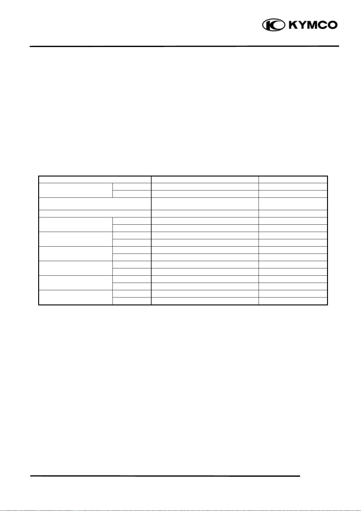
CYLINDER COMPRESSION TEST
Warm up the engine to normal operating
temperature.
Stop the engine and remove the spark plug
cap and remove the spark plug (page 3-7).
XCITING 500
Park Plug Cap
Install a compression gauge into the spark
plug hole.
Open the throttle all the way and crank the
engine with the starter motor until the gauge
reading stops rising.
The maximum reading is usually reached 4 –
7 seconds.
*
To avoid discharging the battery, do not
operate the starter motor for more than
seven seconds.
Compression pressure:
13 kg/cm2 (185 psi, 1300 kPa)
Low compression can be caused by:
Blown cylinder head gasket
Improper valve adjustment
Valve leakage
Worn piston ring or cylinder
Compression Gauge
High compression can be caused by:
Carbon deposits in combustion chamber or
on piston head
8-4
Page 6
8. CYLINDER HEAD/VALVES
CYLINDER HEAD COVER
DISASSEMBLY
Remove the floorboard (page 2-6).
Remove the spark plug caps (page 8-4)
Disconnect the crankcase breather hose from
the cylinder head cover (page 7-3).
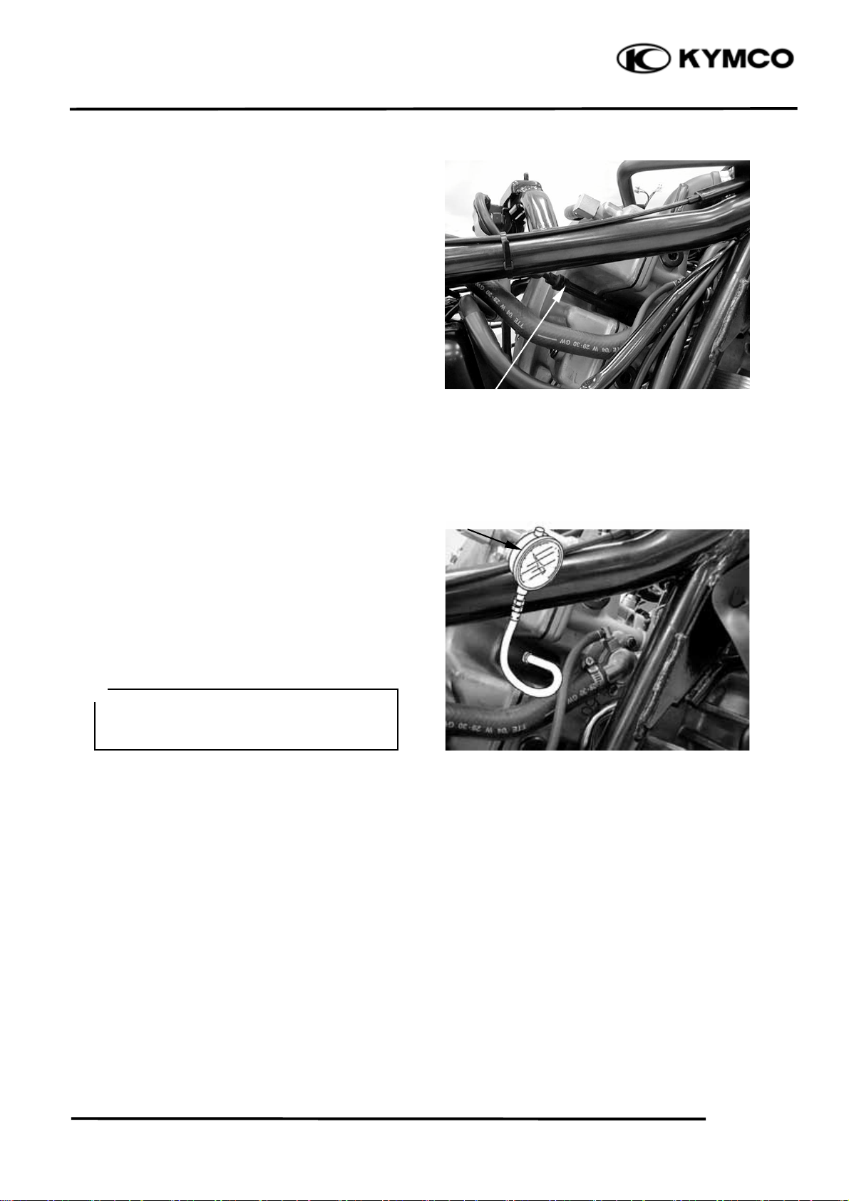
Remove the four bolts and head cover.
Remove the cylinder head cover packing.
XCITING 500
Bolts
Cylinder Head Cover
Cylinder Head Cover Packing
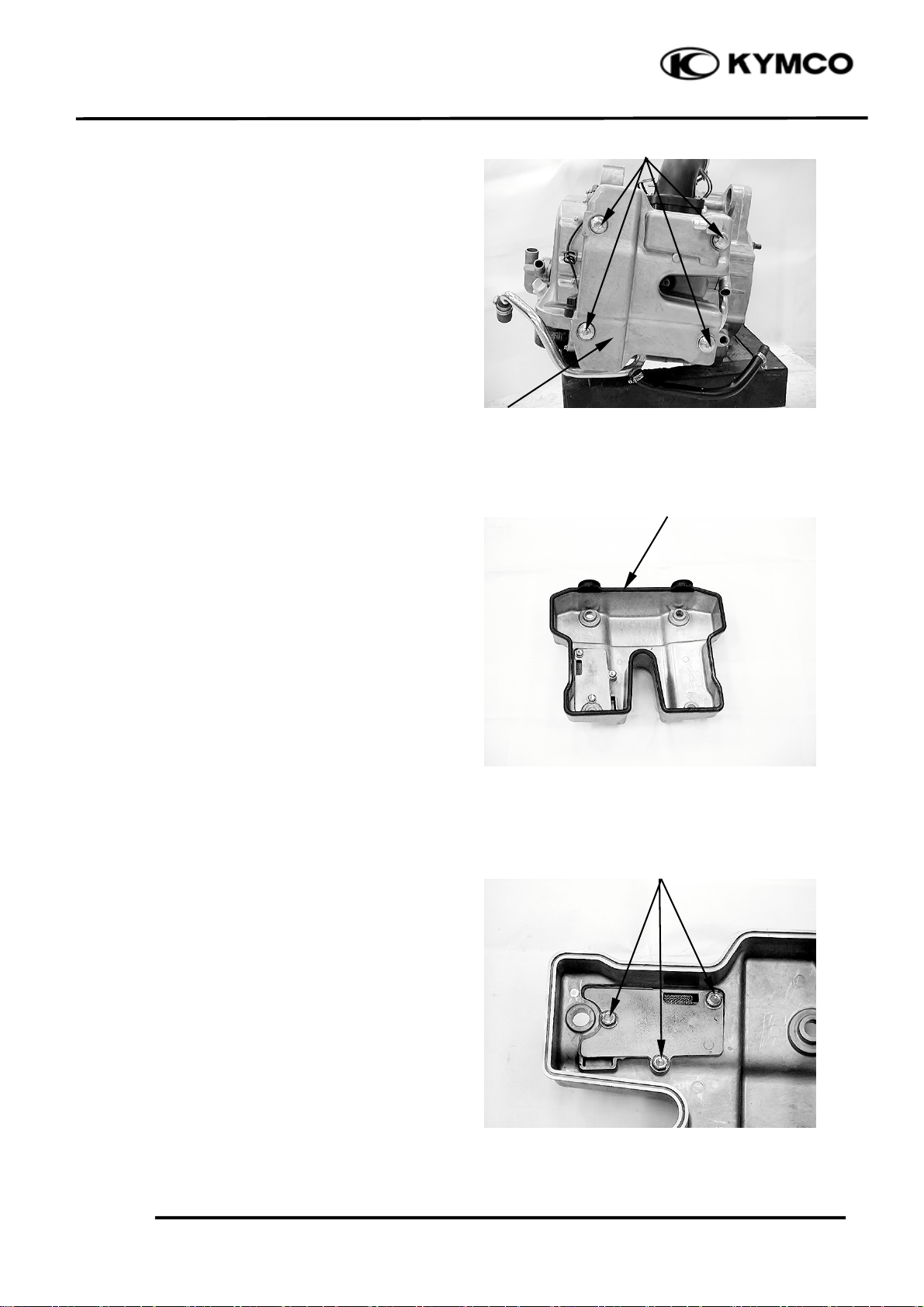
Remove the bolts and breather separator.
8-5
Bolts
Page 7
8. CYLINDER HEAD/VALVES
t
r
t
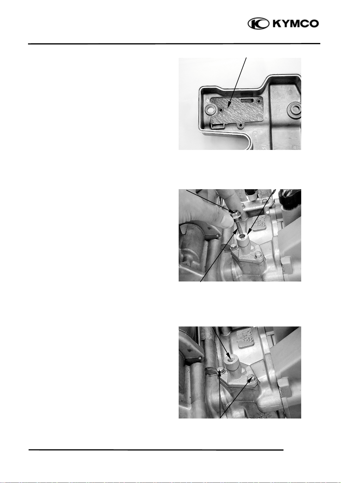
Remove the gasket.
ASSEMBLY
Assembly is in the reverse order of
disassembly.
Torque:
Breather separator bolt:
13 N•m (1.3 kgf•m, 9 lbf•ft)
CAMSHAFT REMOVAL
Remove the cylinder head cover (page 8-5).
Turn the crankshaft clockwise and align the
“T” mark on the flywheel with the index
mark on the right crankcase cover (page 3-9).
XCITING 500
Gaske
Bolt Washe
Remove the cam chain tensioner lifter sealing
bolt, spring and sealing washer.
Remove the two bolts, cam chain tensioner
and gasket.
Spring
Cam Chain Tensioner/Gaske
Bolts
8-6
Page 8
8. CYLINDER HEAD/VALVES
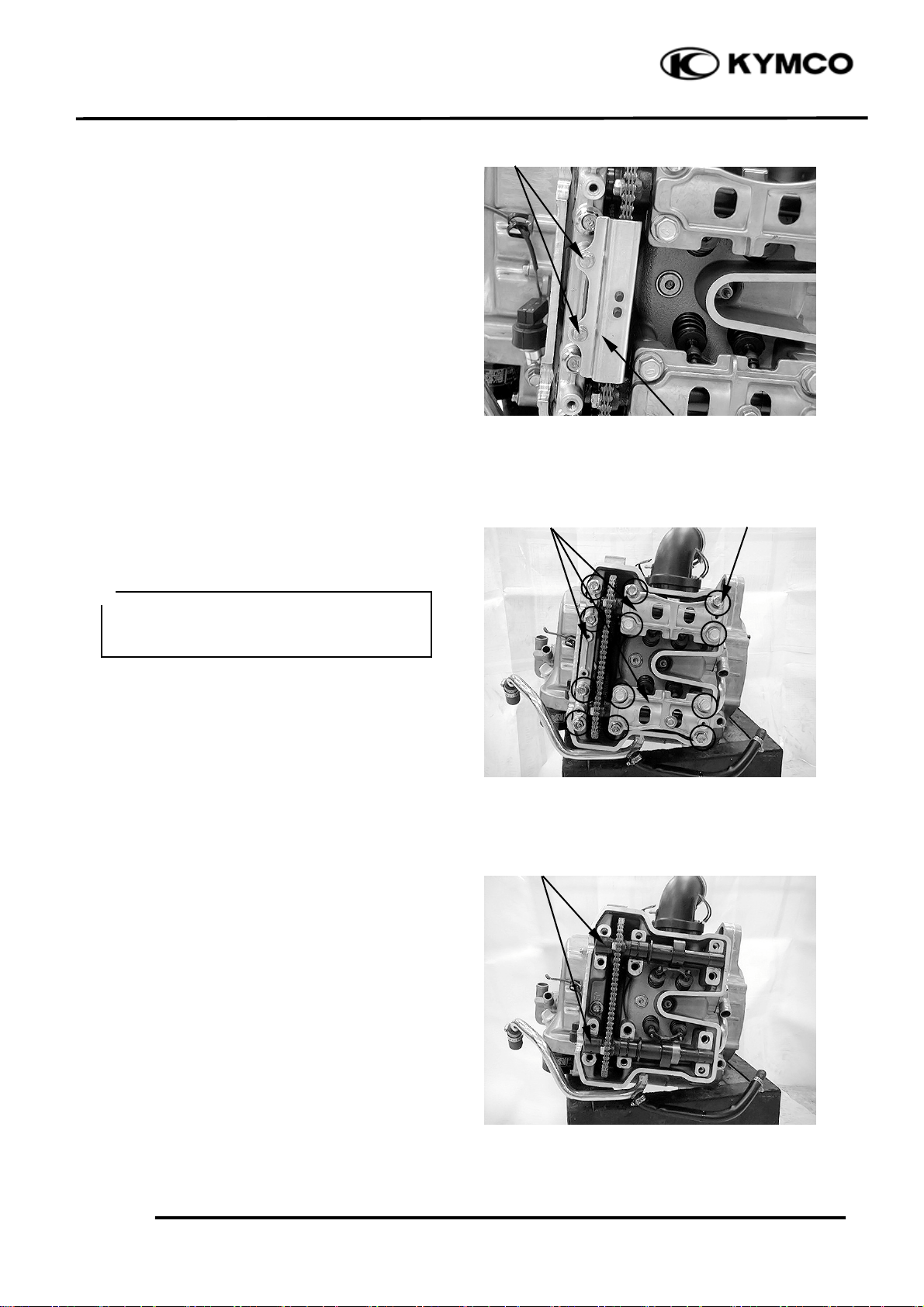
Remove the two bolts and cam chain guide.
XCITING 500
Bolts
Cam Chain Guide
Loosen and remove the twelve camshaft
holder bolts in a crisscross pattern in several
steps, then remove the camshaft holders.
*
Suspend the cam chain with a piece of
wire to prevent the chain from falling
into the crankcase.
Remove the camshafts
Camshaft Holders Bolts
Camshafts
8-7
Page 9

8. CYLINDER HEAD/VALVES
INSPECTION
Cam chain guide
Inspect the am chain slipper surface of the
cam chain guide for wear or damage.
Camshaft holder
Inspect the bearing surface of each camshaft
holder for scoring, scratches, or evidence of
insufficient lubrication.
XCITING 500
Spark Plug Cap
Check the stop pin spring on the exhaust
camshaft holder for damage.
Replace the stop pin assembly with a new one
if the spring is damage.
Stop Pin
8-8
Page 10

8. CYLINDER HEAD/VALVES
XCITING 500
Camshaft
Support both ends of the camshaft with Vblocks and check the camshaft runout with a
dial gauge.
Service limit: 0.05 mm (0.002 in)
Inspect camshaft lobes for
pitting/scratches/blue discoloration.
Measure the cam lobe height.
Service Limits: IN : 37.11 mm (1.4844 in)
EX: 36.86 mm (1.4744 in)
If any defects are found, replace the camshaft
with a new one, then inspect lubrication
system.
Check the decompression system by turning
the decompressor cam on the exhaust
camshaft.
You should be able to turn the decompressor
cam clockwise smoothly, but the
decompressor should not turn
counterclockwise.
8-9
Page 11

8. CYLINDER HEAD/VALVES
t
Cam chain tensioner
Check the one-way cam operation (tensioner)
Unsmooth operation → Replace.
XCITING 500
Rocker Arms
ROCKER ARMS REMOVAL
Remove the camshaft (page 8-6)
Remove the rocker arm shafts and washers,
then remove the rocker arms.
INSPECTION
Rocker arm shaft
Inspect the rocker arm shaft for blue
discoloration or grooves.
If any defects are found, replace the rocker
arm shaft with a new one, then inspect
lubrication system.
Rocker Arm Shafts/Washers
Rocker Arm Shaf
Measure each rocker arm shaft O.D.
Measure the I.D. of each rocker arm.
Measure arm to shaft clearance.
Replace as a set if out of specification.
Service limits: 0.1 mm (0.004 in)
8-10
Page 12

8. CYLINDER HEAD/VALVES
t
r
m
XCITING 500
Inspect the rocker arm bore, cam lobe contact
surface and adjuster surface for
wear/pitting/scratches/blue discoloration.
If any defects are found, replace the rocker
arm shaft with a new one, then inspect
lubrication system.
Measure each rocker arm shaft O.D.
Measure the I.D. of each rocker arm.
Measure arm to shaft clearance.
Replace as a set if out of specification.
Service limits: 0.1 mm (0.004 in)
CYLINDER HEAD REMOVAL
Remove the rock arms (page 8-10).
Rock Ar
Intake Pipe/Insulato
Remove the two bolts, intake pipe and
insulator.
Remove the two bolts, two nuts, pair reed
valve and gasket.
Bolts
Pair Reed Valve Gaske
8-11
Nuts
Page 13

8. CYLINDER HEAD/VALVES
Remove the two bolts, water joint, gasket and
water stop collar.
Remove the three bolts and cylinder head.
XCITING 500
Bolts
Water Joint/Gasket/Water Stop Collar
Cylinder Head
Remove the dowel pins and cylinder head
gasket.
Bolts
Dowel Pins
Gasket
8-12
Page 14

8. CYLINDER HEAD/VALVES
r
XCITING 500
DISSASEMBLY
CYLINDER HEAD DISASSEMBLY
Remove the valve spring cotters, retainers,
springs, spring seats, oil seals and valves
using a valve spring compressor.
Valve Spring Compresso
*
• Be sure to compress the valve springs
with a valve spring compressor.
• Mark all disassembled parts to ensure
correct reassembly.
Special tool:
Valve Spring Compressor E040
Valve Spring Cotters Retainers Valves
Springs Spring Seats Oil Seals
8-13
Page 15

8. CYLINDER HEAD/VALVES
VALVE /VALVE GUIDE INSPECTION
Inspect each valve for bending, burning,
scratches or abnormal stem wear.
If any defects are found, replace the valve
with a new one.
Check valve movement in the guide.
Measure each valve stem O.D.
Measure each valve guide I.D.
Subtract each valve stem O.D. from the
corresponding guide I.D. to obtain the stemto-guide clearance.
Service limits:
IN: 0.08 mm (0.0032 in)
EX: 0.1 mm (0.004 in)
*
If the stem-to-guide clearance exceeds
the service limits, replace the cylinder
head is necessary.
XCITING 500
CYLINDER HEAD INPECTION
Check the spark plug hole and valve areas for
cracks.
Check the cylinder head for warpage with a
straight edge and feeler gauge.
Service Limit: 0.05 mm (0.002 in)
VALVE SPRING INSPECTION
Measure the free length of the inner and outer
valve springs.
Service Limit: Inner: 35.2 mm (1.408 in)
Outer: 39.8 mm (1.592 in)
8-14
Page 16

8. CYLINDER HEAD/VALVES
r
Measure compressed force (valve spring) and
installed length.
Replace if out of specification.
Standard:
Inner: 3.5 kg (at 28.7 mm, 1.148 in)
Outer: 13 kg (at 31.43 mm, 1.2572 in)
Measure the spring tilt.
Replace if out of specification.
Standard: Inner: 1.2 mm (0.048)
Outer: 1.2 mm (0.048)
XCITING 500
ASSEMBLY
Install the valve spring seats and oil seal.
*
Be sure to install new oil seal.
Lubricate each valve with engine oil and
insert the valves into the valve guides.
Install the valve springs with the small-pitch
portion (1) facing cylinder head. (2) Largepitch portion.
Put on the valve sparing retainers.
Compress the valve springs using the valve
spring compressor, then install the valve
cotters.
*
• When assembling, a valve spring
compressor must be used.
• Install the cotters with the pointed ends
facing down from the upper side of the
cylinder head.
(2)
(1)
Valve Spring Compresso
Special tool:
Valve Spring Compressor E040
8-15
Page 17

8. CYLINDER HEAD/VALVES
XCITING 500
Tap the valve stems gently with a plastic
hammer for 2~3 times to firmly seat the
cotters.
*
Be careful not to damage the valves.
CYLINDER HEAD
INSTALLATION
Install the dowel pins and new cylinder head
gasket as shown.
Dowel Pins
Install the cylinder head.
Apply engine oil to the cylinder head bolt (9)
threads.
Install the two cylinder bolts and cylinder
head bolt (9) but do not tighten them.
Gasket
Cylinder Bolts Cylinder Head
Cylinder Head Bolt (9)
8-16
Page 18

8. CYLINDER HEAD/VALVES
t
t
Install the water stop collar, gasket and water
joint.
Install and tighten the two bolts to the
specified torque.
Torque: 12 N•m (1.2 kgf•m, 9 lbf•ft)
XCITING 500
Bolts Water Stop Collar Gaske
Water Joint
.
Install gasket and pair reed valve.
Install and tighten the four bolts securely.
Install the new O-rings onto the insulator and
intake pipe.
Pair Reed Valve Gaske
Bolts
O-ring O-ring
8-17
Page 19

8. CYLINDER HEAD/VALVES
r
r
XCITING 500
Install the insulator with the O-ring face the
cylinder head.
Install the intake pipe and tighten the two
bolts securely.
Insulato
O-ring
Intake Pipe
ROCKER ARM INSTALLATION
Apply engine oil to the rocker arms and
rocker arm shafts
Install the rocker arms, rocker arm shafts and
washers.
Tighten the rocker arm shaft to the specified
torque.
Torque: 45 N•m (4.5 kgf•m, 32 lbf•ft)
Bolts
Rocker Arm Washe
Rocker Arm Shaft
8-18
Page 20

8. CYLINDER HEAD/VALVES
XCITING 500
CAMSHAFT INSTALLATION
Turn the crankshaft clockwise, align the “T”
mark on the flywheel with the index mark on
the right crankcase cover (page 3-9).
Apply molybdenum disulfide oil to the
camshaft journals of the camshaft holder.
Apply molybdenum disulfide oil to the
camshaft journals of the cylinder head.
Install the cam chain over the cam sprockets
and then install the intake and exhaust
camshafts.
*
Install each camshafts to the correct
locations.
“IN”: no decompressor cam
“EX”: has a decompressor cam (page 8-
9)
Make sure the timing marks on the cam
sprockets are flush with the cylinder
head upper surface and punch marks
face upward as shown.
Punch Marks
Timing Marks
8-19
Page 21

8. CYLINDER HEAD/VALVES
Install intake and exhaust camshaft holders to
the correct locations.
*
Install each camshaft holders to the
correct locations.
“IN”: no stop pin.
“EX”: has a stop pin.
Apply engine oil to cylinder head bolt (No.
1 – 9) threads.
Install and tighten the holder bolts (No. 1 – 9)
in a crisscross pattern in four steps to the
specified torque as follow diagram.
Tighten the bolts to the specified torque in sequence
N•m (kgf•m, lbf•ft)
XCITING 500
Stop Pin Exhaust Camshaft Holder
(1) (2) (3) (4) (5) (6) (7) (8) (9)
Step 1 18 (1.8, 13) ←←←12 (1.2, 9) ←←←←
Step 2 48 (4.8, 35) ←←←23 (2.3, 17) ←←←←
8-20
Page 22

8. CYLINDER HEAD/VALVES
Install the common camshaft holder by arrow
mark facing outside.
Install and tighten the holder bolts (No. 10 –
13) in a crisscross pattern in four steps to the
specified torque as follow diagram.
Tighten the bolts to the specified torque in sequence
N•m (kgf•m, lbf•ft)
(10) (11) (12) (13)
Step 1 12 (1.2, 9) ←←←
Step 2 23 (2.3, 17) ←←←
XCITING 500
*
Apply engine oil to cylinder head bolt
(No. 10 – 13) threads.
“Arrow” Mark
Tighten the two cylinder bolts to the specified
torque.
Torque: 10 N•m (1 kgf•m, 7 lbf•ft)
8-21
Cylinder Bolts
Page 23

8. CYLINDER HEAD/VALVES
r
XCITING 500
Install the cam chain guide and tighten the
two bolts securely.
Release the timing chain tensioner one-way
cam and push the tensioner rod all the way in.
Bolts
Cam Chain Guide
Install the tensioner with a new gasket onto
the cylinder.
Install and tighten the tensioner bolts to
specified torque.
Torque: 12 N•m (1.2 kgf•m, 9 lbf•ft)
Install the spring, washer and timing chain
tensioner cap bolt to specified torqur.
Torque: 10 N•m (1 kgf•m, 9 lbf•ft)
Adjust the valve clearance (page 3-9).
Cap Bolt Washe
Spring Bolts
8-22
Page 24

8. CYLINDER HEAD/VALVES
XCITING 500
CYLINDER HEAD COVER
INSTALLATION
Install the cylinder head packing into the
groove of the cylinder head cover.
Install the cylinder head cover onto the
cylinder head and tighten the cylinder head
cover bolts to the specified torque.
Torque: 10 N•m (1 kgf•m, 7 lbf•ft)
Cylinder Head Cover Packing
Bolts
Cylinder Head Cover
8-23
 Loading...