

Page 1

13. CRANKCASE/CRANKSHAFT
XCITING 500
13
__________________________________________________________________________________
__________________________________________________________________________________
__________________________________________________________________________________
__________________________________________________________________________________
__________________________________________________________________________________
13
CRANKCASE/CRANKSHAFT
__________________________________________________________________________________
SCHEMATIC DRAWING ------------------------------------------------- 13- 1
SERVICE INFORMATION------------------------------------------------ 13- 2
TROUBLESHOOTING----------------------------------------------------- 13- 2
CAM CHAIN/CAM CHAIN GUIDE REMOVAL --------------------- 13- 3
CRANKCASE SEPARATION -------------------------------------------- 13- 4
CRANKCASE ASSEMBLY ----------------------------------------------- 13-11
13-0
Page 2
13. CRANKCASE/CRANKSHAFT
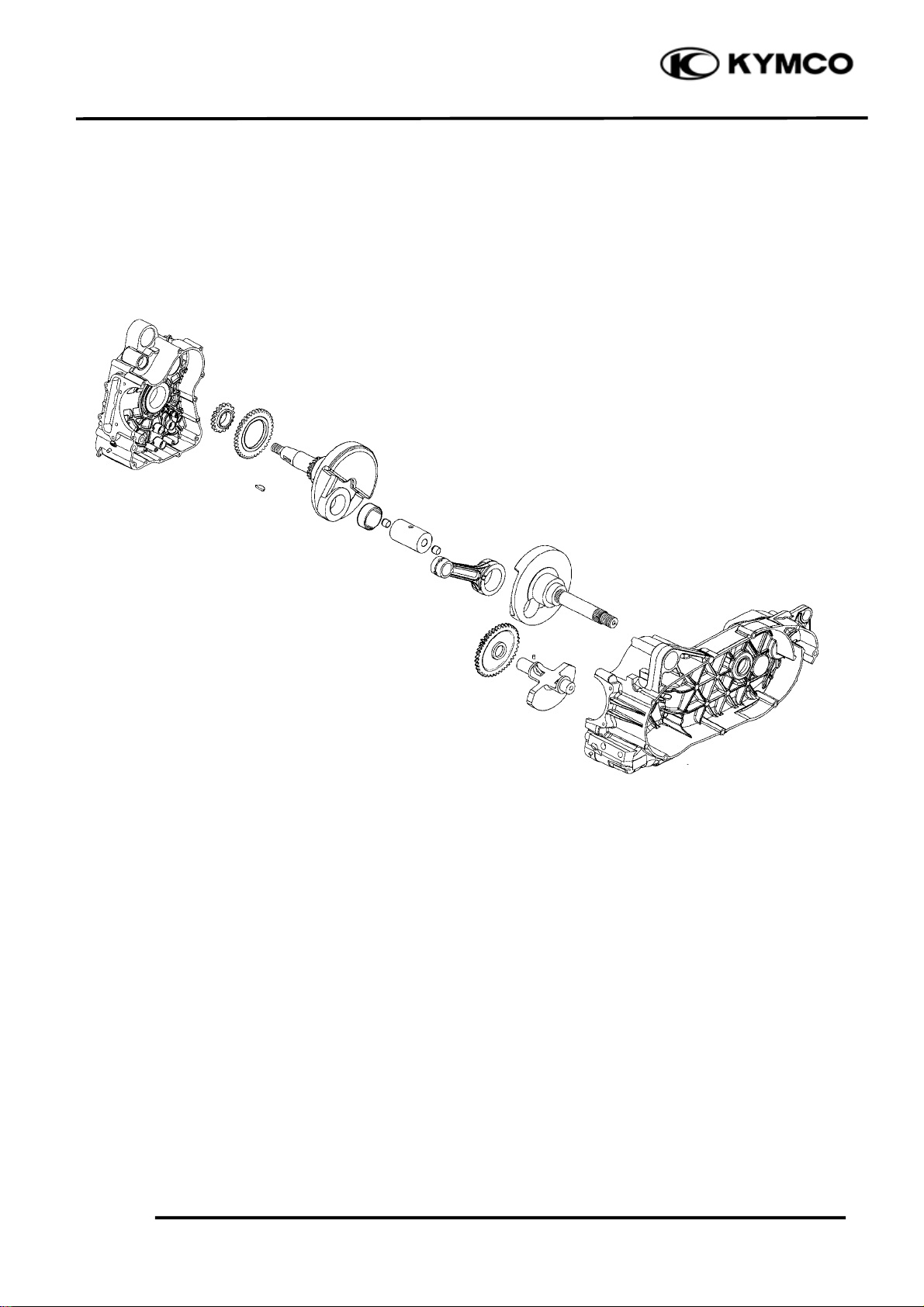
SCHEMATIC DRAWING
XCITING 500
13-1
Page 3
13. CRANKCASE/CRANKSHAFT
m
d
XCITING 500
SERVICE INFORMATION
GENERAL INSTRUCTIONS
• This section covers crankcase separation to service the crankshaft and balancer. The engine must
be removed for this operation.
• When separating the crankcase, never use a driver to pry the crankcase mating surfaces apart
forcedly to prevent damaging the mating surfaces.
• When installing the crankcase, do not use an iron hammer to tap it.
• The following parts must be removed before separating the crankcase.
Cylinder head (section 8)
Cylinder/piston (section 9)
Drive and driven pulley (section 10)
A.C. generator/starter clutch (section 12)
Starter motor (section 19)
Oil pump (section 4)
SPECIFICATIONS Unit: mm (in)
Ite
Main bearing oil clearance
Crankshaft
TORQUE VALUES
Crankcase bolt 12 N•m (1.2 kgf•m, 9 lbf•ft)
Cam chain guide bolt 20 N•m (2 kgf•m, 15 lbf•ft)
Oil pipe bolt 43 N•m (4.3 kgf•m, 31 lbf•ft)
SPECIAL TOOLS
Bearing puller E037
Oil seal & bearing driver E014
Connecting rod big end side
clearance
Runout
0.025 (0.001)~0.041 (0.0016) 0.07 (0.003)
0.05 (0.002)~0.5 (0.02) 0.8 (0.031)
Standar
⎯ 0.06 (0.002)
Service Limit
TROUBLESHOOTING
Excessive engine noise
• Worn connecting to small end
• Worn or damaged crankshaft bearings
13-2
Page 4
13. CRANKCASE/CRANKSHAFT
CAM CHAIN/CAM CHAIN GUIDE
REMOVAL
Remove the starter driven gear (page 12-4).
Remove the cylinder (page 9-3).
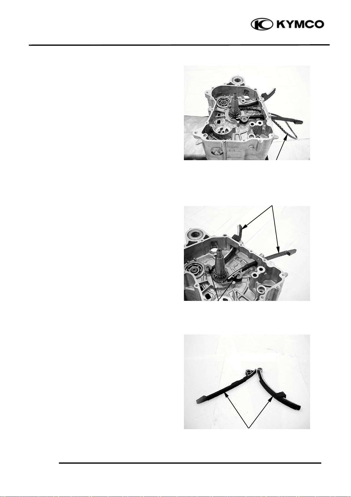
Remove the cam chain from the right
crankcase.
Cam Chain
Cam Chain Guides
XCITING 500
Remove the bolts and cam chain guides.
INSPECTION
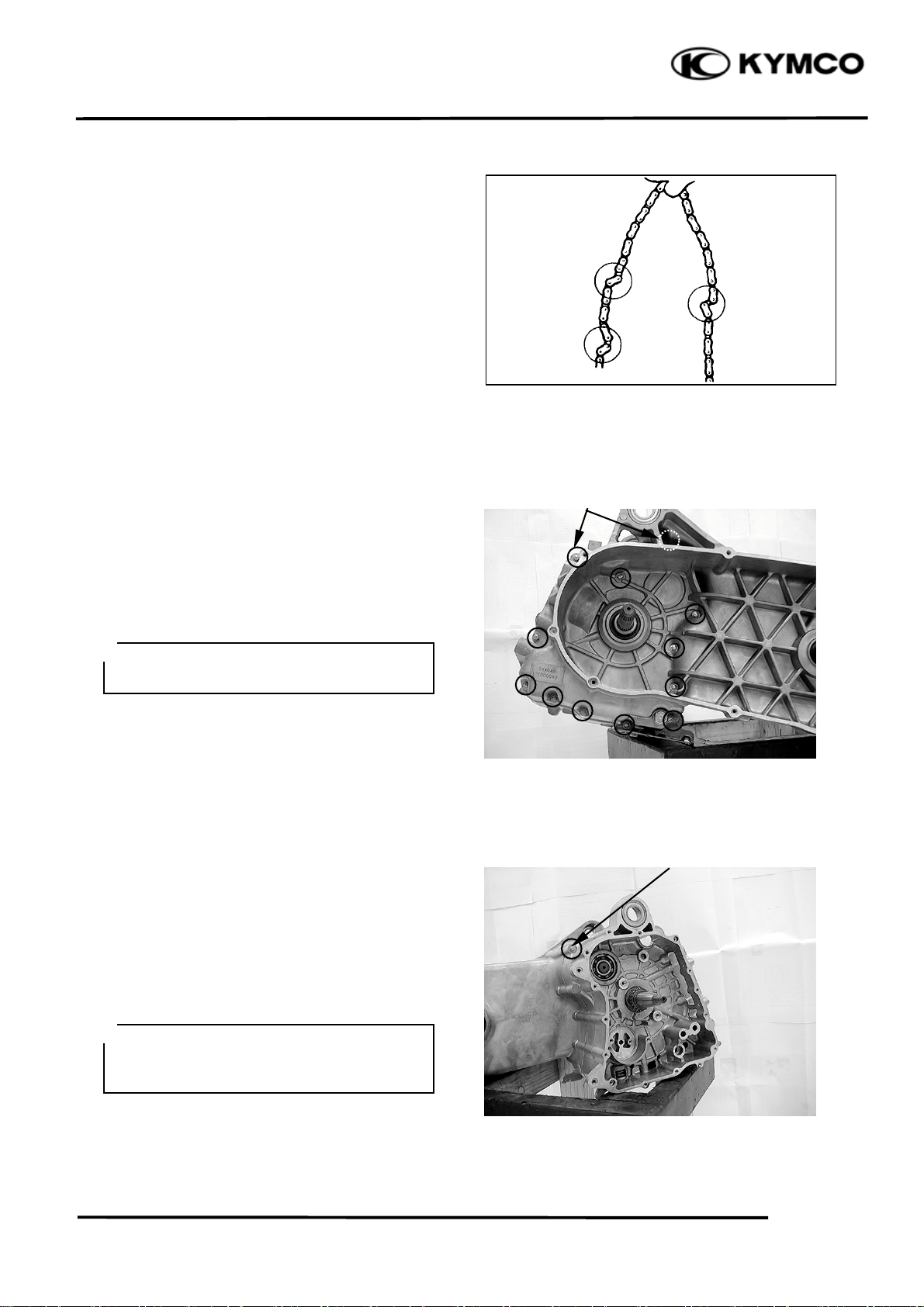
Cam chain guide
Inspect the cam chain slipper surface of the
cam chain guide for wear or damage.
Bolts
13-3
Slipper Surface
Page 5
13. CRANKCASE/CRANKSHAFT
t
Cam chain
Inspect the cam chain for cracks or stiff.
Bolts
CRANKCASE SEPARATION
Remove the parts required for crankcase
separation (page 13-2).
XCITING 500
Remove the twelve bolts from left crankcase.
*
Loosen the bolts in a crisscross pattern in
several steps.
Remove the bolt from right crankcase.
Place the crankcase assembly with the left
side down and separate the right crankcase
from the left crankcase.
*
Separate the right crankcase from the left
crankcase while tapping them at several
locations with a soft hammer.
Bol
13-4
Page 6

13. CRANKCASE/CRANKSHAFT
r
t
Dowel Pins
Remove the dowel pins and O-ring.
Remove the oil collar and O-rings from the
left crankcase.
Clean of the sealant from the left and right
crankcase mating surfaces.
Oil Collar/O-rings Dowel Pin/O-ring
Washe
XCITING 500
Remove the washer from the crankshaft.
Remove the balancer shaft from the left
crankcase.
Remove the crankshaft from the left
crankcase.
Crankshaf
13-5
Page 7

13. CRANKCASE/CRANKSHAFT
r
Bolts/Outer Washe
RIGHT CRANKCASE DISASSEMBLY
Remove the two bolts, outer washer, oil pipe
and inner washers.
Oil Pipe/Inner Washers
Inner Washers
RIGHT CRANKCASE ASSEMBLY
Install the inner washers onto the right
crankcase.
XCITING 500
Install the oil pipe with the thick side face
upward.
Thick Side
Oil Pipe
13-6
Page 8

13. CRANKCASE/CRANKSHAFT
r
Bolts/Outer Washe
Install the outer washers and two bolts.
Tighten the two bolts to the specified torque.
Torque: 43 N•m (4.3 kgf•m, 31 lbf•ft)
XCITING 500
CRANKSHAFT/CRANKCASE
SELECTION
Crankcase and crankshaft are select fitted.
Record the main journal O.D. code (- or
+)
Record the main journal bearing I.D. color
code (green, brown or yellow).
Record the right or left crankcase main
journal I.D. code (A or B).
If the crankcase and/or crankshaft are
replaced, select them with the following
fitting table.
The “U” mark in the table indicates that
mating is possible in the crossed code.
Main Journal Bearing I.D. Color Cod
Main Journal O.D. Code
e
Main journal O.D. code
Main journal bearing I.D. color code
/Crankcase main journal I.D. code
Green/A U
Green/B U
Brown/A U
Yellow/B U
13-7
+-
Crankcase Main Journal I.D. Code
Page 9

13. CRANKCASE/CRANKSHAFT
XCITING 500
MAIN BEARING INSPECTION
Inspect the bearing inserts for unusual wear,
damage or peeling and replace the crankcase
if necessary.
Main bearing oil clearance
Clean off any oil from the main bearing
inserts and crankshaft journals.
Measure and record the crankshaft main
journal O.D..
Measure and record the main bearing I.D..
Calculate the oil clearance by subtracting the
journal O.D. from bearing I.D..
Standard:
0.025 – 0.041 mm (0.001 – 0.0016 in)
Service limit: 0.07 mm (0.003 in)
Replace the crankcase if the service limit is
exceeded.
Select the replacement crankcase (page 13-7).
Bearing
Runout Side Clearance Runout
CRANKSHAFT INSPECTION
Measure the connecting rod big end side
clearance.
Service limit: 0.8 mm (0.031 in)
Measure the crankshaft runout.
Service limit: 0.06 mm (0.002 in)
BALANCER SHAFT INSPECTION
Inspect the balance shaft gear teeth.
Burrs/chips/roughness/wear → Replace.
Journals
Bolts
Balancer Shaft
13-8
Page 10

13. CRANKCASE/CRANKSHAFT
r
BALANCER SHAFT BEARING
REPLACMENT
Remove the crankshaft and balancer shaft
(page 13-4).
Turn the inner race of each bearing with your
finger.
The bearings should turn smoothly and
quietly. Also check that the bearing outer race
fits tightly in the crankcase.
Replace the bearings if the races does not turn
smoothly and quietly, or if they fit loosely in
the crankcase.
Bearing Pulle
Remove the balancer shaft bearing from the
left crankcase using the special tool.
XCITING 500
Special tool: Bearing puller E037
Remove the bearing snap ring from right
crankcase.
Bearing
Bolts
13-9
Snap Ring
Page 11

13. CRANKCASE/CRANKSHAFT
r
XCITING 500
Remove the balancer shaft bearing from the
right crankcase.
Install the snap ring into the right crankcase.
Bearing
Snap Ring
Install the new bearings to the right and left
crankcase using special tool.
Special tool:
Oil seal & bearing driver E014
Oil Seal & Bring Drive
Breaing
13-10
Page 12

13. CRANKCASE/CRANKSHAFT
t
t
r
Crankshaf
CRANKCASE ASSEMBLY
Install the crankshaft to the left crankcase.
Align Balancer Shaf
Install the balancer shaft to align the punch
mark with the “O” mark on the crankshaft.
XCITING 500
Install the washer onto the crankshaft.
13-11
Left Front Cover
Washe
Page 13

13. CRANKCASE/CRANKSHAFT
t
XCITING 500
Install the oil collar and O-rings
Clean the right and left crankcase mating
surface thoroughly, being careful not to
damage them.
Install the dowel pins and O-ring.
Apply a light but through coating of sealant
(Threebond 1215 or equivalent) to all
crankcase mating surfaces except the oil
passage area.
Dowel Pins
Oil Collar/O-rings Dowel Pin/O-ring
Bol
Install the right crankcase over the left
crankcase.
Install and turn in the right crankcase bolt but
do not tighten it.
Install and tighten the left crankcase bolts in a
crisscross pattern in 2 – 3 steps to the
specified torque.
Torque: 12 N•m (1.2 kgf•m, 9 lbf•ft)
Tighten the right crankcase bolt to the
specified torque.
Torque: 12 N•m (1.2 kgf•m, 9 lbf•ft)
Bolts
Make sure that the crankshaft turns smoothly.
13-12
Page 14

13. CRANKCASE/CRANKSHAFT
XCITING 500
Install the cam chain guides to the right
crankcase and tighten the bolts to the
specified torque.
Torque: 20 N•m (2 kgf•m, 15 lbf•ft)
Install the cam chain to right crankcase.
Cam Chain Guides
Cam Chain
13-13
 Loading...