

Page 1

18. IGNITION SYSTEM
XCITING 500
18
__________________________________________________________________________________
__________________________________________________________________________________
__________________________________________________________________________________
__________________________________________________________________________________
__________________________________________________________________________________
IGNITION SYSTEM
__________________________________________________________________________________
IGNITION SYSTEM LAYOUT------------------------------------------- 18-1
SERVICE INFORMATION------------------------------------------------ 18-2
TROUBLESHOOTING----------------------------------------------------- 18-2
IGNITION COIL INSPECTION ------------------------------------------ 18-4
IGNITION CONTROL MODULE ---------------------------------------- 18-5
18
18-0
Page 2
18. IGNITION SYSTEM
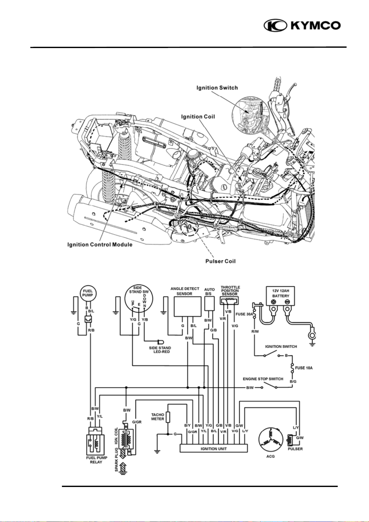
IGNITION SYSTEM LAYOUT
XCITING 500
IGNITION CIRCUIT
18-1
Page 3

18. IGNITION SYSTEM
XCITING 500
SERVICE INFORMATION
GENERAL INSTRUCTIONS
● Some electrical components may be damaged if terminals or connectors are connected or
disconnected while the ignition switch is “ON” and current is present.
● When servicing the ignition system, always follow the steps in the troubleshooting on page ???.
● The ignition timing cannot be adjusted since the ignition control module is factory preset.
● The ignition control module may be damaged if dropped. Also, if the connector is disconnected
when current is flowing, the excessive voltage may damage the ignition control module. Always
turn off the ignition switch before servicing.
● A faulty ignition system is often related to poor connections. Check those connections before
proceeding.
● Make sure the battery is adequately charged. Using the starter motor with a weak battery results in
a slower engine cranking speed as well as no spark at the spark plug.
● Use a spark plug of the correct heat range. Using spark plug with an incorrect heat range can
damage the engine.
● See section 12 for ignition pulse generator removal/installation.
● See section 20 for following components:
ä Ignition switch
ä Engine stop switch
SPECIFICATIONS
Item Standard
Spark plug NGK-CR8E
Spark plug gap 0.7 mm (0.028 in)
Ignition system Full transistor digital ignition
Ignition timing TPS
TROUBLESHOOTING
LOW PEAK VOLTAGE
● Cranking speed is too low (battery is undercharged).
● Poorly connected connectors or an open circuit in the ignition system.
● Faulty ignition-coil.
● Faulty ignition control module.
NO PEAK VOLTAGE
● Short circuit in engine stop switch or ignition switch wire.
● Faulty engine stop switch or ignition switch.
● Loose or poorly connected ignition control module connectors.
● Open circuit or poor connection in ground wire of the ignition control module.
● Faulty ignition pulse generator.
● Faulty ignition control module.
18-2
Page 4

18. IGNITION SYSTEM
PEAK VOLTAGE IS NORMAL, BUT NO SPARK JUMPS AT THE PLUG
● Faulty spark plug or leaking ignition coil secondary current.
● Faulty ignition coil.
XCITING 500
18-3
Page 5

18. IGNITION SYSTEM
XCITING 500
IGNITION COIL INSPECTION
IGNITION COIL PRIMARY PEAK
VOLTAGE
Remove the floorboard (page 2-6).
Check cylinder compression and check that the
spark plugs is installed correctly in the cylinder.
Disconnect the spark plug cap from the spark
plug.
Connect known good spark plug to the spark
plug cap and ground the spark plugs to the
cylinder as done in the spark test.
Spark Plug Cap
Turn the ignition switch to “ON” and engine
stop switch ON.
Connect the multimeter (+) probe to the
Black/White wire and the multimeter (-) to the
body ground.
Check for initial voltage at this time.
The battery voltage should be measured.
If the initial voltage cannot be measured, check
the power supply circuit.
Spark Plug Cap
Spark Plug Cap
18-4
Page 6

18. IGNITION SYSTEM
r
IGNITION PULSE GENERATOR
INSPECTION
Remove the luggage box (page 2-3).
Disconnect the ignition pulse generator
connector.
Measure the ignition pulse generator resistance
between the Green/White wire and Blue/Yellow
wire.
Standard: 516Ω (20ºC/68ºF)
IGNITION COIL
REMOVAL/INSTALLATION
Remove the floorboard (page 2-6).
Disconnect the spark plug cap from the spark
plug (page 18-4).
XCITING 500
Ignition Pulse Generator Connecto
Disconnect the ignition coil primary connectors.
Remove the two nuts and the ignition coil.
Installation is in the reverse order of removal.
IGNITION CONTROL MODULE
REMOVAL/INSTALLATION
Remove the side body cover (page 2-8).
Disconnect the ignition control module
connectors and remove the ignition control
module.
Spark Plug Cap
Ignition Control Module Connectors
18-5
Ignition Control Module
Page 7

18. IGNITION SYSTEM
/
/Gr
RESISTANCE INSPECTION
Measure the resistance between the terminals.
B
W G/B V/B
XCITING 500
*
Due to the semiconductor in circuit, it
is necessary to use a specified tester for
accurate testing. Use of an improper
tester in an improper range may give
false readings.
G
G
V/G
L/Y
G/W B/Y V/R Y/L B/L Y/G
Unit: Ω
(+)
(-)
L/Y 91.6K 6.67M 6.68M 46.2K 49.5K 150K 46.2K 12.59M 49.7K
G/GR 9.5M 9.3M ←↑9.23M 9M 9.16M 8.97M 8.96M ↑
G/W 91.8K 6.67M 6.68M ↑ 47K 50.3K 150.9K 47K 12.59M 50.3K ↑
B/Y 15.96M ↑ 15.6M 994 ↑ 15.33M 14.88M 15.04M 14.74M 3.35M 14.7M ↑
L/Y G/GR G/W B/Y B/W G/B G V/R V/B V/G Y/L B/L Y/G
B/W 15.96M ↑ 15.6M 994 ↑ 14.96M 14.88M 15.02M 14.74M 3.35M 14.7M ↑
G/B ↑ ←← ←←←←←←↑
G 44.3K ↑ 44.9K 6.62M 6.63M ↑ 3.54K 103.9K ∞ 12.51M 3.54K ↑
V/R 47.5K ↑ 48.4K 6.62M 6.63M ↑ 3.53K 100.2K 3.54K 12.51M 1.99K ↑
V/B 148.5K ↑ 149.4K 6.75M 6.76M ↑ 102.8K 99.3K 102.7K 12.67M 101.2K ↑
V/G 44.3K ↑ 44.9K 6.62M 6.63M ↑ ∞ 3.55K 103.9K 12.51M 3.55K ↑
Y/L 8.13M ↑ 8.1M ←↑7.81M 7.77M 7.91M 7.72M 7.72M ↑
B/L 47.5K ↑ 48.4K 6.62M 6.62M ↑ 3.53K 1.99K 102.2K 3.53K 12.51M ↑
Y/G ↑ ←←←←←←←←←
18-6
 Loading...