

Page 1

20. LIGHTS/METERS/SWITCHES
XCITING 500
20
__________________________________________________________________________________
__________________________________________________________________________________
__________________________________________________________________________________
__________________________________________________________________________________
__________________________________________________________________________________
LIGHTS/METERS/SWITCHES
__________________________________________________________________________________
SERVICE INFORMATION------------------------------------------------ 20- 1
BULB REPLACEMENT --------------------------------------------------- 20- 2
SPEED SENSOR ------------------------------------------------------------ 20- 5
BRAKE LIGHT SWITCH-------------------------------------------------- 20- 7
IGNITION SWITCH -------------------------------------------------------- 20- 7
HANDLEBAR SWITCH --------------------------------------------------- 20- 8
PARKING SWITCH -------------------------------------------------------- 20-10
LUGGAGE BOX LIGHT SWITCH -------------------------------------- 20-10
OIL PRESSURE SWITCH------------------------------------------------- 20-10
FUEL UNIT ------------------------------------------------------------------ 20-13
SIDE STAND SWITCH ---------------------------------------------------- 20-15
HORN ------------------------------------------------------------------------- 20-16
BANK ANGLE SENSOR -------------------------------------------------- 20-17
HEATER CONTROL UNIT ----------------------------------------------- 20-18
20
20-0
Page 2

20. LIGHTS/METERS/SWITCHES
XCITING 500
SERVICE INFORMATION
GENERAL
*
A halogen head light bulb becomes very hot while the head light is on, and remains for a while
after it is turned off. Be sure to let it cool down before servicing.
• Note the following when replacing the halogen headlight bulb
ä Wear clean gloves while replacing the bulb. Do not put finger prints on the headlight bulb,
as they may create hot spots on the bulb and cause it to fail.
ä If you touch the bulb with your bare hands, clean it with a cloth moistened with alcohol to
prevent its early failure.
ä Be sure to install the dust cover after replacing the bulb.
• Check the battery condition before performing any inspection that requires proper battery
voltage.
• A continuity test can be made with the switches installed on the scooter.
• Route the wires and cables properly after servicing each component.
20-1
Page 3
20. LIGHTS/METERS/SWITCHES
r
BULB REPLACEMENT
HEADLIGHT
*
A halogen headlight bulb becomes very
hot while the headlight is ON, and
remain for a while after it is turned OFF.
Be sure to let it cool down before
servicing.
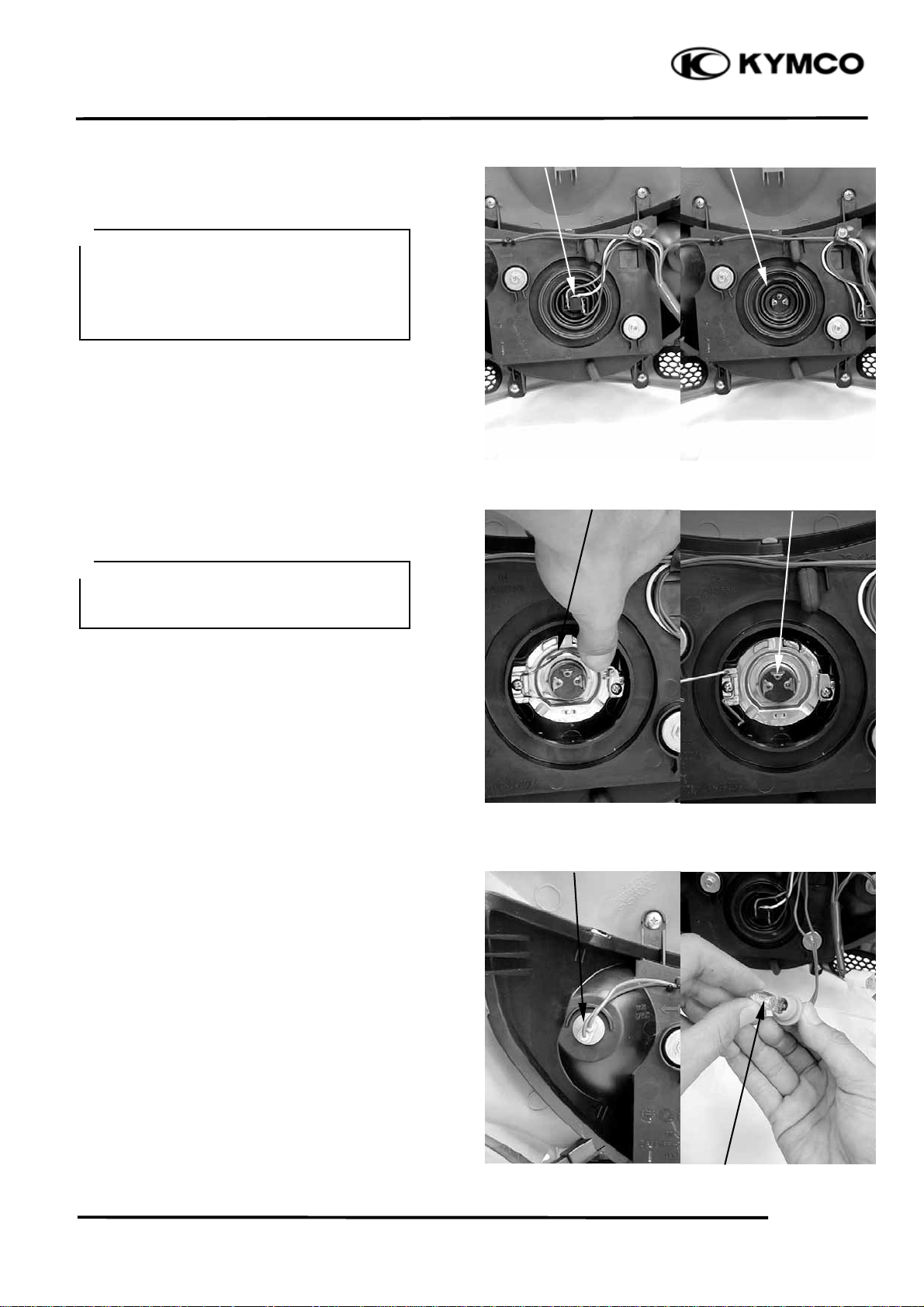
Remove the front cover (page 2-11)
Disconnect the headlight connector from the
headlight bulb and remove the dust cover.
Unhook the retainer and remove the bulb from
the headlight case.
XCITING 500
Headlight Connector Dust Cove
Retainer Bulb
*
Avoid touching the halogen headlight
bulb. Finger prints can create hot spots
that cause a bulb to break.
Install a new bulb in the headlight case, by
aligning the bulb tab with the case groove.
Hook the retainer.
Install the dust cover properly on to the
headlight and connect the headlight connector
POSITION LIGHT
Remove the front cover (page 2-11).
Remove the bulb socket and position light bulb.
Remove the bulb and replace with a new one.
Installation is in the reverse order of removal.
Socket
Bulb
20-2
Page 4
20. LIGHTS/METERS/SWITCHES
t
XCITING 500
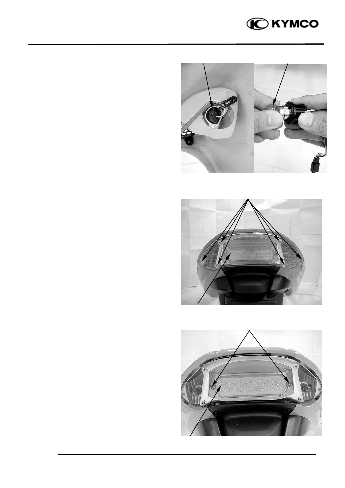
FRONT TURN SIGNAL
Remove the front cover (page 2-11).
Turn the bulb socket counterclockwise to
remove it.
Remove the bulb and replace with a new one.
Installation is in the reverse order of removal.
TAILLIGHT/BRAKE LIGHT, REAR TURN
SIGNAL
Remove the six screws and lens.
Socket Bulb
Screws
Taillight/Brake light
Remove the two screws and remove the
taillight/brake light.
20-3
Lens
Screws
Taillight/Brake Ligh
Page 5
20. LIGHTS/METERS/SWITCHES
r
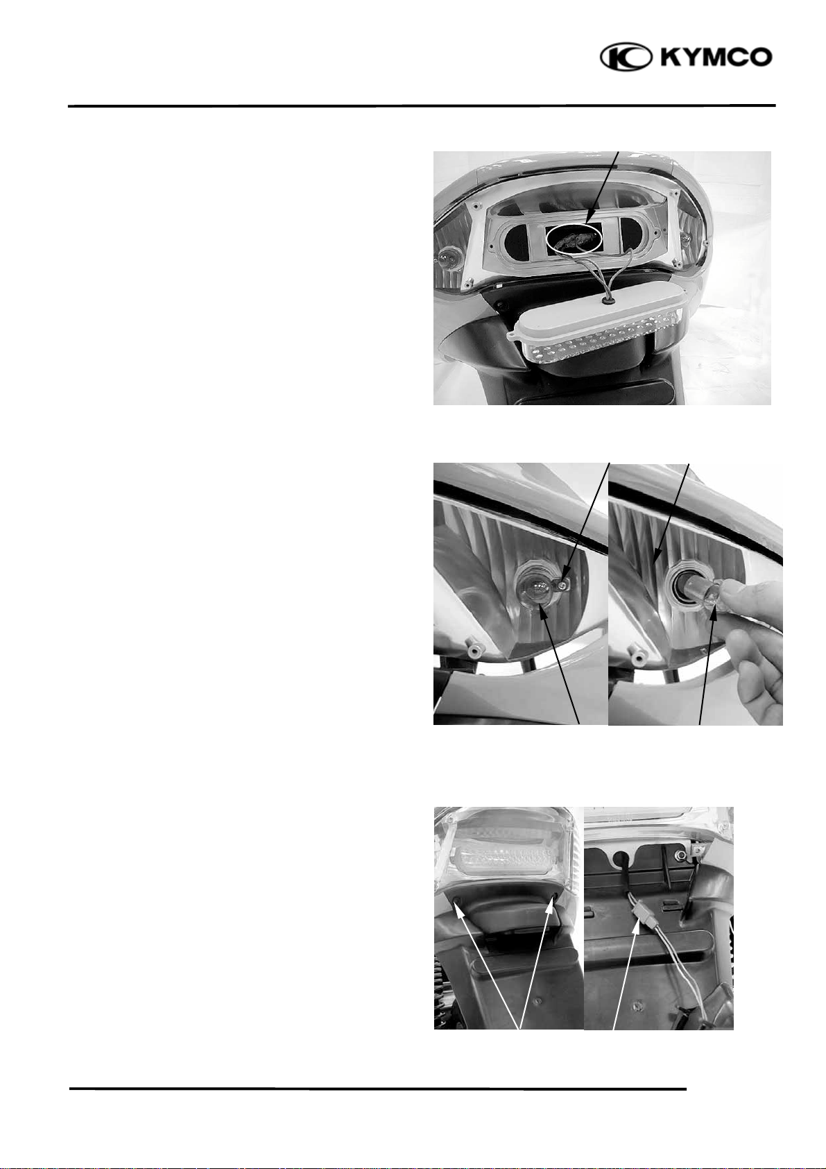
Connectors
Disconnect the taillight/brake light connectors.
Installation is in the reverse order of removal.
Screw
Rear turn signal
Remove the screw and bulb cap.
Remove the bulb and replace with a new one.
XCITING 500
Installation is in the reverse order of removal.
LICENSE LIGHT
Remove two screws.
Disconnect the license light connector and
remove the license light.
Cap Bulb
Screws Connecto
20-4
Page 6
20. LIGHTS/METERS/SWITCHES
r
r
r
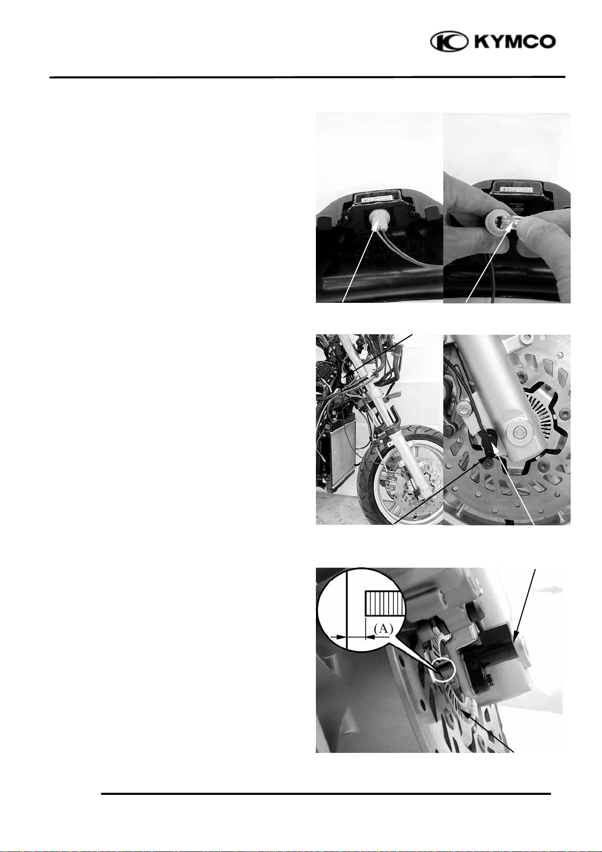
Remove the bulb socket and license light bulb.
Remove the bulb and replace with a new one.
Installation is in the reverse order of removal.
Socket Bulb
Speed Sensor connecto
SPEED SENSOR
REMOVAL/INSTALLATION
Remove the front cover (page 2-11).
XCITING 500
Disconnect the speed sensor connector.
Remove the bolt and speed sensor.
Installation is in the reverse order of removal.
INSPECTION
Measure the speed sensor to speed sensor guide
clearance.
Standard (A): 0.3 – 1.2 mm (0.0012 – 0.048 in)
Bolt Speed Senso
Speed Senso
20-5
Speed Sensor Guide
Page 7

20. LIGHTS/METERS/SWITCHES
r
t
Speed Senso
ADJUSTMENT
Remove the bolt and speed sensor.
Bol
Remove the speed sensor cap.
XCITING 500
Loosen the lock screws and adjust speed sensor
to the standard clearance.
Standard: 0.3 – 1.2 mm (0.0012 – 0.048 in)
Cap
Lock Screw
Lock Screw
20-6
Page 8

20. LIGHTS/METERS/SWITCHES
XCITING 500
BRAKE LIGHT SWITCH
Remove the upper handlebar cover (page 2-5).
Disconnect front or rear light switch connector
and check for continuity between the switch
terminals.
There should be continuity with the front or rear
brake lever squeezed, and there should be no
continuity with the front or rear brake lever is
released.
IGNITION SWITCH
INSPECTION
Brake Light Switch
Connector Ignition Switch (Comb Switch)
Remove the front cover (page 2-11).
Disconnect the ignition switch connector and
check for continuity at the switch side connector
terminals.
Continuity should exist between the color code
wires as follows:
20-7
Page 9

20. LIGHTS/METERS/SWITCHES
Light Switch
HANDLEBAR SWITCH
INSPECTION
Remove the front cover (page 2-11).
Right handlebar switch
Disconnect the right handlebar switch connector
and check for continuity at switch side connector
terminals.
Continuity should exist between the color code
wires as follows:
Starter Switch
XCITING 500
Hazard Switch
Engine Stop Switch
20-8
Page 10

20. LIGHTS/METERS/SWITCHES
XCITING 500
Left handlebar switch
Disconnect the left handlebar switch connector
and check for continuity at switch side connector
terminals.
Continuity should exist between the color code
wires as follows:
Turn Signal Switch (Winker Switch)
Horn Switch
Passing Switch
20-9
Dimmer Switch
Page 11

20. LIGHTS/METERS/SWITCHES
r
r
r
XCITING 500
PARKING SWITCH
INSPECTION
Remove the front cover (page 2-11).
Disconnect the parking switch connector and
check for continuity between the switch
terminals.
There should be continuity with the parking
lever pull up, and there should be no continuity
with the front brake lever is push down.
LUGGAGE BOX LIGHT SWITCH
INSPECTION
Remove the luggage box (page 2-3).
Parking Brake Switch Connecto
Luggage Box Light Switch
Disconnect the luggage box light switch
connector and check for continuity between the
switch terminals.
There should be no continuity with the luggage
box light switch pushed, and there should be
continuity with the luggage box light switch is
released.
OIL PRESSURE SWITCH
INSPECTION
If the oil pressure warning indicator stays on
while the engine running, check the engine oil
level before inspection.
Make sure that the oil pressure warning
indicator come on with the ignition switch ON.
Switch Connecto
Oil Pressure Warning Indicato
20-10
Page 12

20. LIGHTS/METERS/SWITCHES
r
Dust Cove
If the indicator does not come on, inspect as
follow:
Remove the dust cover and disconnect oil
pressure switch terminal.
Oil Pressure Switch Terminal
Short the oil pressure switch wire terminal with
the ground using a jumper wire.
The oil pressure warning indicator comes on
with the ignition switch is ON.
If the light does not comes on, check the fuse
and wires for a loose connection or an open
circuit.
XCITING 500
Start the engine and make sure that the light
goes out.
If the light does not go out, check the internal oil
for leak.
If the engine oil does not leak, replace the oil
pressure switch (see below).
REMOVAL/INSTALLATION
Remove the dust cover and disconnect oil
pressure switch terminal.
Remove the oil pressure switch from the
crankcase.
Oil Pressure Switch
20-11
Page 13

20. LIGHTS/METERS/SWITCHES
r
Apply sealant to the oil pressure switch threads
as shown.
Install the oil pressure switch onto the crankcase,
tighten it to the specified torque.
Torque: 22 N•m (2.2 kgf•m, 16 lbf•ft)
Oil Pressure Switch Terminal
Connect the oil pressure switch terminal to the
switch.
XCITING 500
Install the dust cover.
Dust Cove
20-12
Page 14

20. LIGHTS/METERS/SWITCHES
r
t
Fuel Uni
FUEL UNIT
REMOVAL
Remove the floorboard (page 2-6).
Disconnect the fuel unit connector.
Fuel Unit Wire
Retaine
Turn the fuel unit retainer counterclockwise and
remove it.
XCITING 500
Remove the fuel unit.
*
Be careful not to bend or damage the
fuel unit float arm.
20-13
Page 15

20. LIGHTS/METERS/SWITCHES
INSPECTION
Connect the fuel unit wire connectors and turn
the ignition switch “ON”.
XCITING 500
*
Before performing the following test,
operate the turn signals to determine that
the battery circuit is normal.
Check the fuel meter for correct indication by
moving the fuel unit float up and down.
Float Position Display
Upper Much (Full)
Lower Less (Empty)
Wire Terminals Display
Free From Much to Less
Apply From Less to Much
The fuel meter is normal if it operates as above
indicated. If not, check for poorly connected
terminals or shorted wires.
Upper
INSTALLATION
Install the O-ring and fuel unit.
*
Align the groove on the fuel unit with
the flange on the fuel tank.
Lower
Groove
Flange
20-14
Page 16

20. LIGHTS/METERS/SWITCHES
t
r
r
Install the fuel unit retainer.
*
Align the arrow mark on the fuel unit
retainer with the arrow mark on the fuel
tank.
XCITING 500
SIDE STAND SWITCH
INSPECTION
Remove the left floor skirt (page 2-5).
Disconnect the side stand switch connector.
There should be continuity between the
Yellow/Green and Green with the side stand
retracted.
There should be continuity between the
Yellow/Black and Green with the side stand
applied.
REMOVAL
Remove the left floor skirt (page 2-5).
Disconnect the side stand switch connector.
Remove the bolt and side stand switch from the
side stand.
Side Stand Switch Connecto
Luggage Box Light Connecto
20-15
Bol
Page 17

20. LIGHTS/METERS/SWITCHES
t
r
Installs the side stand switch aligning the switch
pin with the side stand hole.
Install and tighten the side stand switch bolt
securely.
Hole Pin
Connecto
HORN
INSPECTION
Remove the front cover (page 2-11)
XCITING 500
Disconnect the horn connectors from the horn.
Connect a 12 V battery to the horn terminals.
The horn is normal if it sounds when the 12 V
battery is connected across the horn terminals.
REMOVAL/INSTALLATION
Remove the front cover (page 2-11)
Disconnect the horn connectors from the horn.
Remove the nut and horn.
Installation is in the reverse order of removal.
Horn
Nu
20-16
Page 18

20. LIGHTS/METERS/SWITCHES
r
BANK ANGLE SENSOR
INSPECTION
Support the scooter level surface.
Remove the meter panel (page 2-13).
Turn the ignition switch to “ON” and measure
the voltage between the following terminals of
the bank angle sensor connector with the
connector connected.
TERMINAL STANDARD
Black/Blue Battery voltage
Black/White Battery voltage – (0-1 V)
Bank Angle Senso
XCITING 500
The engine should stop as you incline the bank
angle sensor approximately degrees to the left or
right.
REMOVAL/INSTALLATION
Disconnect the bank angle sensor connector.
Remove the two screws, washers and bank angle
sensor.
20-17
Bank Angle Sensor Screws/Washers
Page 19

20. LIGHTS/METERS/SWITCHES
t
t
Installation is in the reverse order of removal.
*
Install the bank angle sensor with its
“UP” mark facing up.
Tighten the mounting screws securely.
XCITING 500
HEATER CONTROL UNIT
INSPECTION
Heater control unit inspection
1.Open ignition switch to check if the brown
/blue wire of it is enough voltage.
2.Put the heater controller unit in refrigerator. Start
engine after keeping the temperature under 10 ±
4℃.
3.Check if the yellow wire of heater controller
unit has output voltage.
Start engine and if the temperature of heater
controller unit is under 10 ± 4℃. Check if the
white/yellow wire of heater controller unit has
output voltage. If it has not any voltage. It is
damaged.
REMOVAL/INSTALLATION
Remove the side body cover (page 2-8).
Remove the nut and heater control unit.
Installation is in the reverse order of removal.
Nu
Heater Control Uni
20-18
 Loading...