

Page 1

16. BRAKE SYSTEM
XCITING 500
16
__________________________________________________________________________________
__________________________________________________________________________________
__________________________________________________________________________________
__________________________________________________________________________________
__________________________________________________________________________________
BRAKE SYSTEM
__________________________________________________________________________________
SCHEMATIC DRAWING ------------------------------------------------- 16- 1
SERVICE INFORMATION------------------------------------------------ 16- 2
TROUBLESHOOTING----------------------------------------------------- 16- 3
BRAKE FLUID -------------------------------------------------------------- 16- 4
BRAKE PAD ----------------------------------------------------------------- 16-10
BRAKE DISC INSPECTION ---------------------------------------------- 16-13
FRONT MASTER CYLINDER ------------------------------------------- 16-14
REAR MASTER CYLINDER --------------------------------------------- 16-18
DELAY VALVE------------------------------------------------------------- 16-22
FRONT BRAKE CALIPER ------------------------------------------------ 16-24
REAR/PARKING BRAKE CALIPER------------------------------------ 16-26
16
PARKING BRAKE LEVER LINK --------------------------------------- 16-31
16-0
Page 2
16. BRAKE SYSTEM
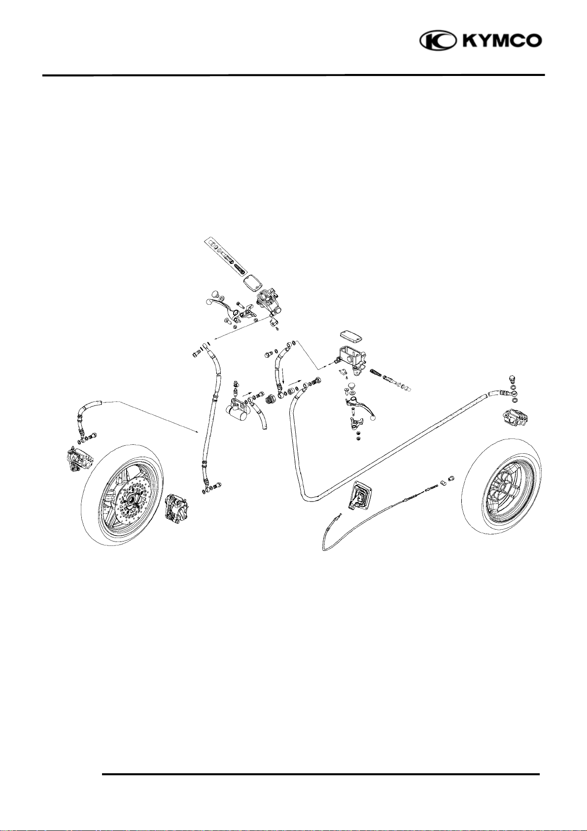
SCHEMATIC DRAWING
XCITING 500
16-1
Page 3
16. BRAKE SYSTEM
r
XCITING 500
SERVICE INFORMATION
GENERAL
*
Frequent inhalation of brake pad dust, regardless of material composition could be hazardous
to your health.
Avoid breathing dust particles.
• A contaminated brake disc or pad reduces stopping power. Discard contaminated parts and clean
a contaminated disc with high quality brake degreasing agent.
• Avoid spilling brake fluid on painted, plastic or rubber parts. Place a rag over these parts
whenever the system is serviced.
• This section covers maintenance of the front and rear hydraulic brake system.
• Never allow contamination (dirt, water, etc.) to get into and open reservoir.
• Once the hydraulic system has been opened, or if the brake feel spongy, the system must be bled.
• Always use fresh DOT 4 brake fluid from a sealed container when servicing the system. Do not
mix different types of fluid as they may not be compatible.
• Always check brake operation before riding the vehicle.
SPECIFICATIONS
ITEM STANDARD SERVICE LIMIT
Front
Rea
Specified brake fluid DOT 4 ⎯
Brake disc thickness 4.8 – 5.2 (0.19 – 0.20) 4 (0.16)
Brake disc runout ⎯ 0.03 (0.012)
Specified brake fluid DOT 4 ⎯
Brake disc thickness 4.8 – 5.2 (0.19 – 0.20) 4 (0.16)
Brake disc warpage ⎯ 0.03 (0.012)
Unit: mm (in)
16-2
Page 4

16. BRAKE SYSTEM
TORQUE VALUES
Master cylinder reservoir cover screw 2 N•m (0.2 kgf•m, 1.4 lbf•ft)
Master cylinder holder bolt 12 N•m (1.2 kgf•m, 9 lbf•ft)
Brake lever pivot bolt 6 N•m (0.6 kgf•m, 4.3 lbf•ft)
Brake lever pivot nut 6 N•m (0.6 kgf•m, 4.3 lbf•ft)
Brake light switch screw 1 N•m (0.1 kgf•m, 0.7 lbf•ft)
Brake caliper mounting bolt 32 N•m (3.2 kgf•m, 23 lbf•ft)
ALOC bolt: replace with a new one.
Brake caliper bleed screw 6 N•m (0.6 kgf•m, 4.3 lbf•ft)
Brake pad pin 18 N•m (1.8 kgf•m, 13 lbf•ft)
Front/Rear caliper pad pin plug 2 N•m (0.2 kgf•m, 1.4 lbf•ft)
Brake hose oil bolt 35 N•m (3.5 kgf•m, 25 lbf•ft)
Delay valve bleed screw 6 N•m (0.6 kgf•m, 4.3 lbf•ft)
TROUBLESHOOTING
XCITING 500
Brake lever soft or spongy Brake lever hard
• Air in the hydraulic system • Clogged/restricted brake system
• Low brake fluid level • Sticking/worn caliper piston
• Clogged fluid passage • Caliper not sliding properly
• Contaminated brake disc/pad • Clogged/restricted fluid passage
• Warped/deformed brake disc • Worn caliper piston seal
• Worn brake disc/pad • Sticking/worn master cylinder piston
• Sticking/worn master cylinder piston • Bent brake lever
• Contaminated master cylinder
• Contaminated caliper Brake drag
• Caliper not sliding properly • Contaminated brake disc/pad
• Leaking hydraulic system • Worn brake disc/pad
• Worn caliper piston seal • Warped/deformed brake disc
• Worn master cylinder piston cups • Caliper not sliding properly
• Bent brake lever
16-3
Page 5
16. BRAKE SYSTEM
m
BRAKE FLUID
Check
Brake fluid: (page 3-18)
Brake hose:
Cracks/wear/damage → Replace.
Apply the brake lever several times.
Fluid leakage → Replace.
Brake hose clamp:
Loosen → Tighten
FLUID REPLACEMENT
Front brake
*
Avoid spilling brake fluid on painted,
plastic or rubber parts and so on. Place a
rag over these parts whenever the system
is serviced.
XCITING 500
Place the scooter on a level surface and keep
the handlebar straight.
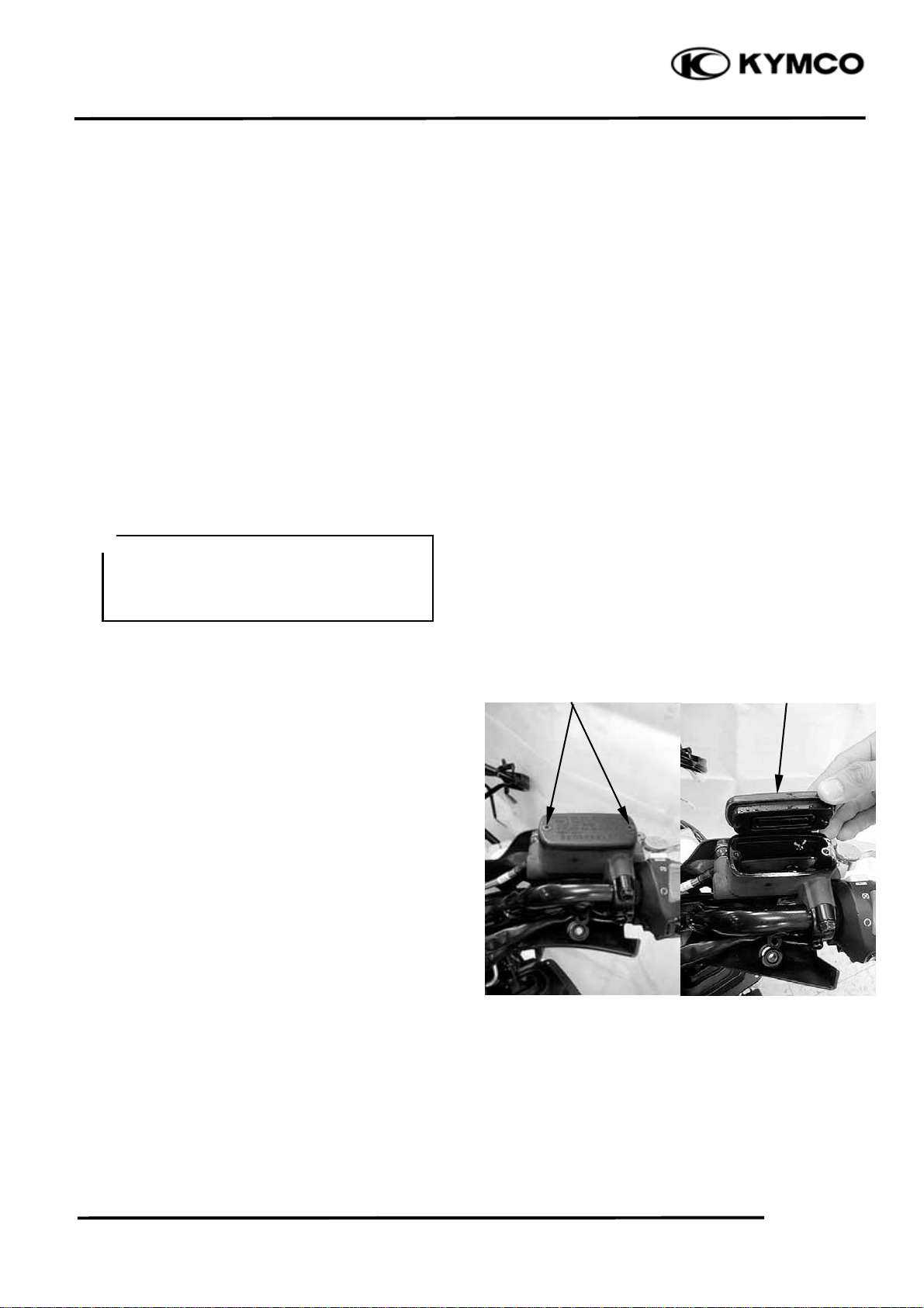
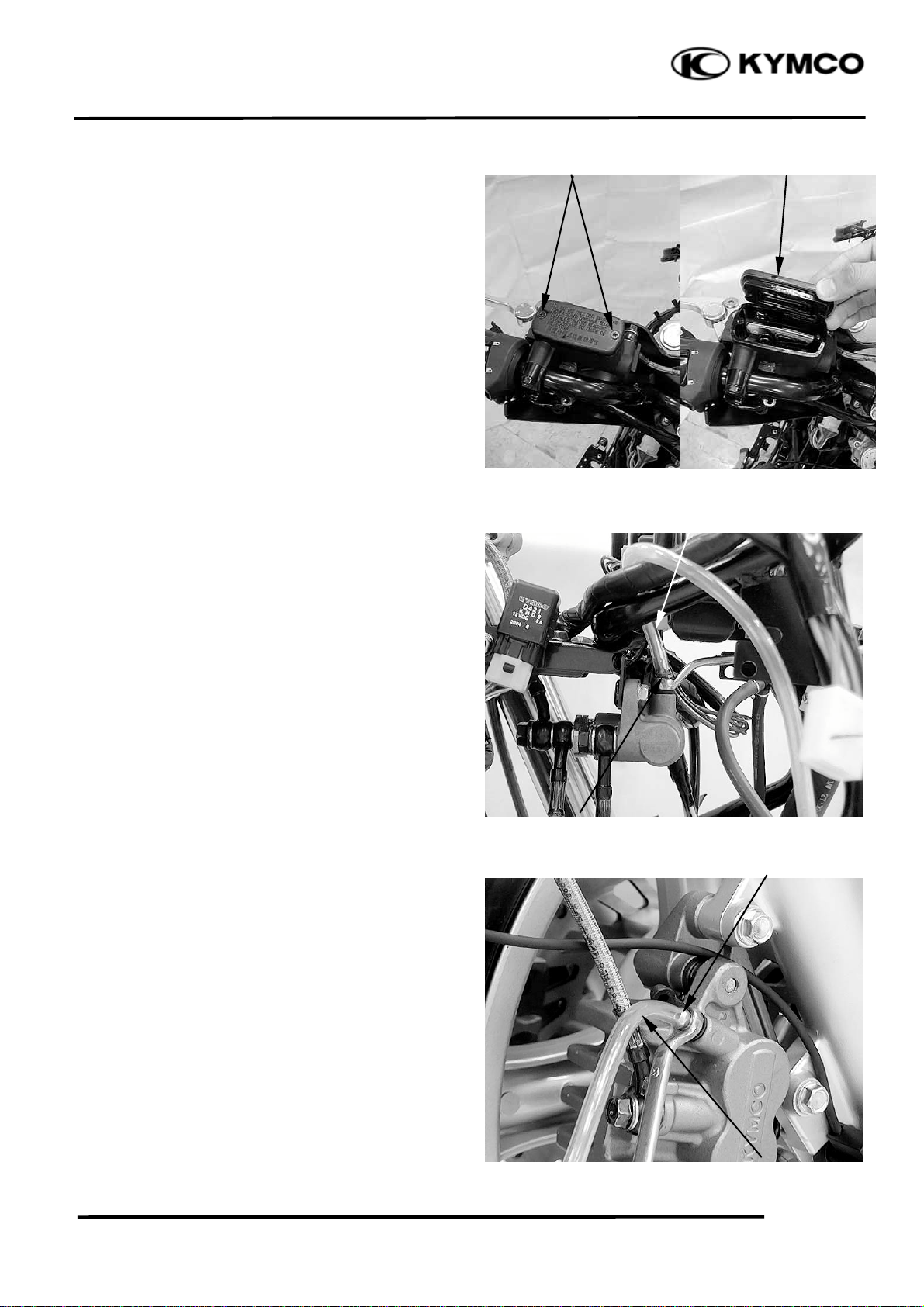
Remove the master cylinder reservoir cap and
diaphragm.
Suck up the old brake fluid as much as
possible.
Fill the reservoir with new brake fluid.
Specification and classification: DOT 4
Screws Cap/Diaphrag
16-4
Page 6
16. BRAKE SYSTEM
r
t
XCITING 500
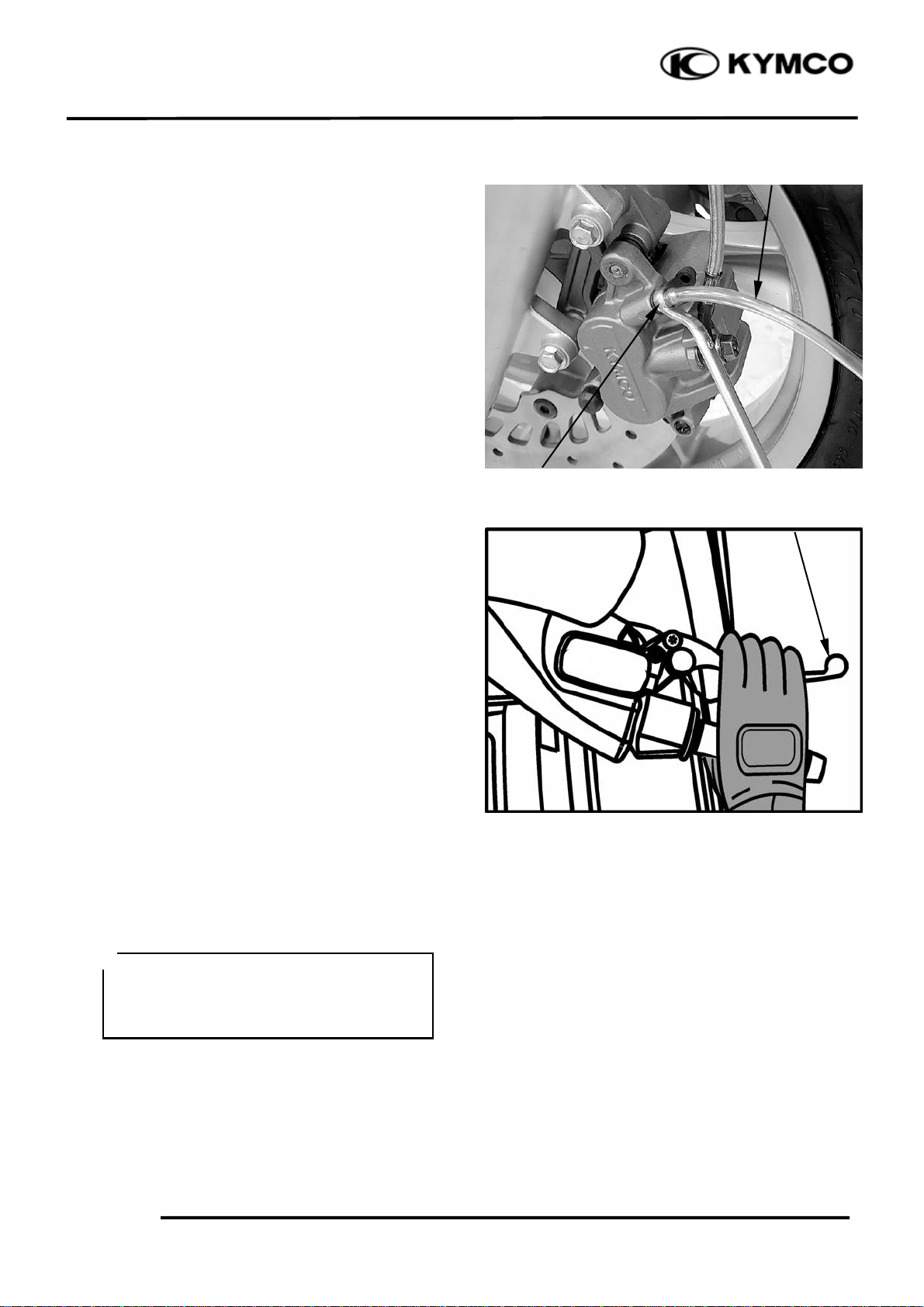
Connect a clear hose to the left front caliper
air bleed screw and insert the other end of the
hose into a receptacle.
Loosen the air bleed screw and pump the
brake lever until the old brake fluid is
completely out of the brake system.
Clear Hose
Left Front Caliper Air Bleed Screw
Brake Leve
Close the air bleed screw and disconnect the
clear hose. Fill the reservoir with new brake
fluid to the upper end of the inspection
window.
Tighten the bleed screw to the specified
torque.
Torque: 6 N•m (0.6 kgf•m, 4.3 lbf•ft)
Combination brake
*
Avoid spilling brake fluid on painted,
plastic or rubber parts and so on. Place a
rag over these parts whenever the system
is serviced.
Place the scooter on a level surface and keep
the handlebar straight.
Shock Absorber Lower Mount Bol
16-5
Page 7
16. BRAKE SYSTEM
m
XCITING 500
Remove the master cylinder reservoir cap and
diaphragm.
Suck up the old brake fluid as much as
possible.
Fill the reservoir with new brake fluid.
Specification and classification: DOT 4
Step 1:
Connect a clear hose to the delay valve air
bleed screw and insert the other end of the
hose into a receptacle.
Loosen the air bleed screw and pump the
brake lever until the old brake fluid is
completely out of the brake system. Close
the air bleed screw and disconnect the clear
hose. Fill the reservoir with new brake fluid
to the upper end of the inspection window.
Screws Cap/Diaphrag
Clear Hose
Step 2:
Connect a clear hose to the right front
caliper air bleed screw. The right brake fluid
replacement is the same way as that of the
step 1.
Relay Valve Air Bleed Screw
Right Front Caliper Air Bleed Screw
Clear Hose
16-6
Page 8
16. BRAKE SYSTEM
XCITING 500
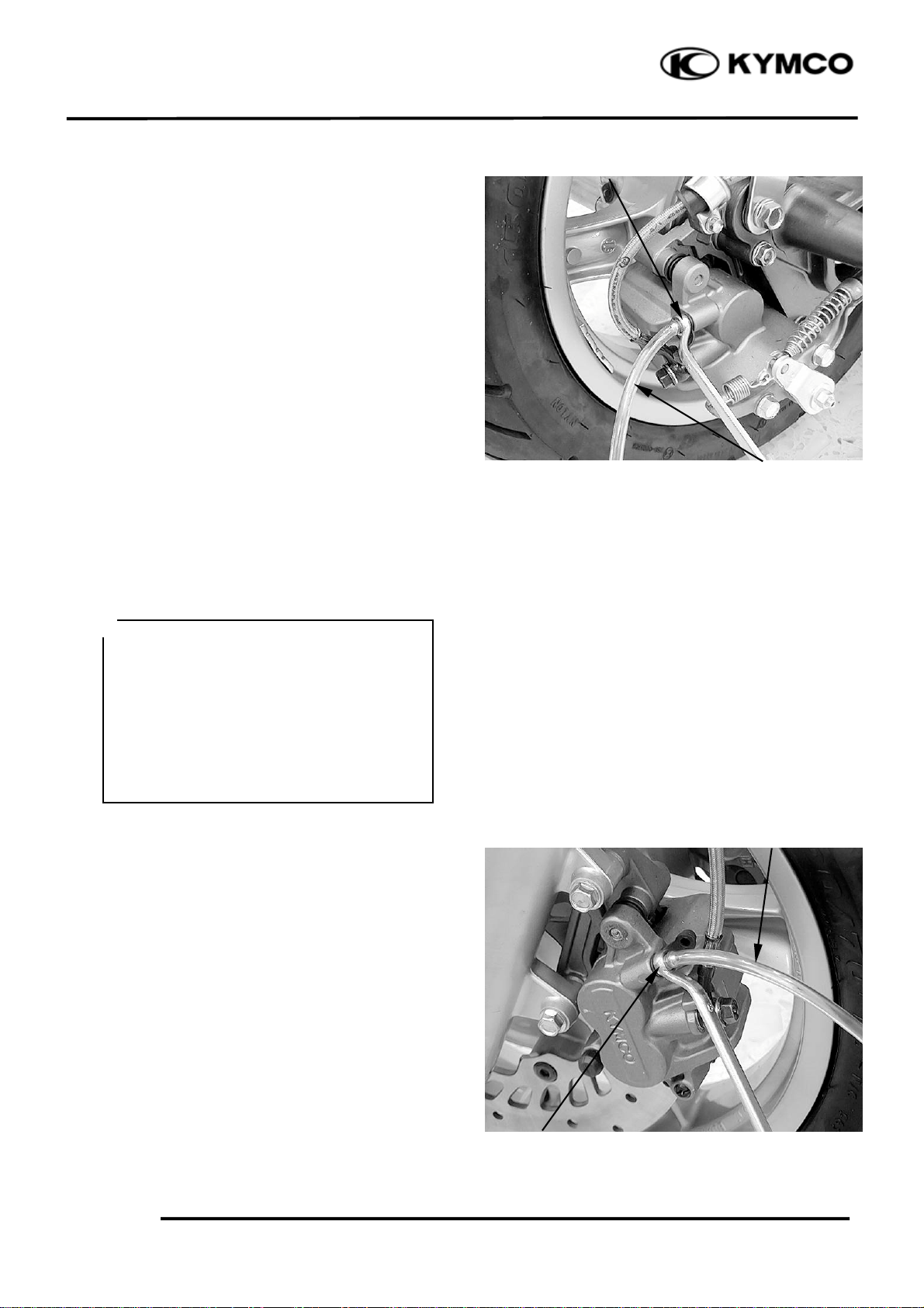
Step 3:
Connect a clear hose to the rear caliper air
bleed screw. The rear brake fluid
replacement is the same way as that of the
step 1.
BLEEDING THE HYDRAULIC BRAKE
SYSTEM
Rear Caliper Air Bleed Screw
Clear Hose
*
Bleed the brake fluid circuit:
● The system has been disassembled.
● A brake hose or brake pipe have been
loosened or removed.
● The brake fluid has been very low.
● The brake operation has been faulty.
A loss of braking performance may occur
if the brake system is not properly bled.
Air bleeding steps (Front brake):
1. Add the proper brake fluid to the reservoir.
2. Install the diaphragm. Be careful not to spill
any fluid or allow the reservoir to overflow.
3. Connect the clear plastic hose tightly to the
left front caliper air bleed screw.
4. Place the other end of the hose into a
container.
5. Slowly apply the brake lever several times.
6. Pull the lever in and hold it.
7. Loosen the bleed screw and allow the
lever to travel towards its limit.
Clear Hose
Left Front Caliper Air Bleed Screw
16-7
Page 9
16. BRAKE SYSTEM
8. Tighten the bleed screw when the lever
limit has been reached, then release the
lever.
9. Repeat steps (5) to (7) until all the air
bubbles have disappeared from the fluid.
10. Tighten the bleed screw.
Torque: 6 N•m (0.6 kgf•m, 4.3 lbf•ft)
*
If bleeding is difficult, it may be
necessary to let the brake fluid settle for
a few hours.
Repeat the bleeding procedure when the
tiny bubbles in the system have
disappeared.
12. Add brake fluid to the proper level and
install the master cylinder reservoir cap
and diaphragm.
XCITING 500
*
Check the operation of the brake after
bleeding the brake system.
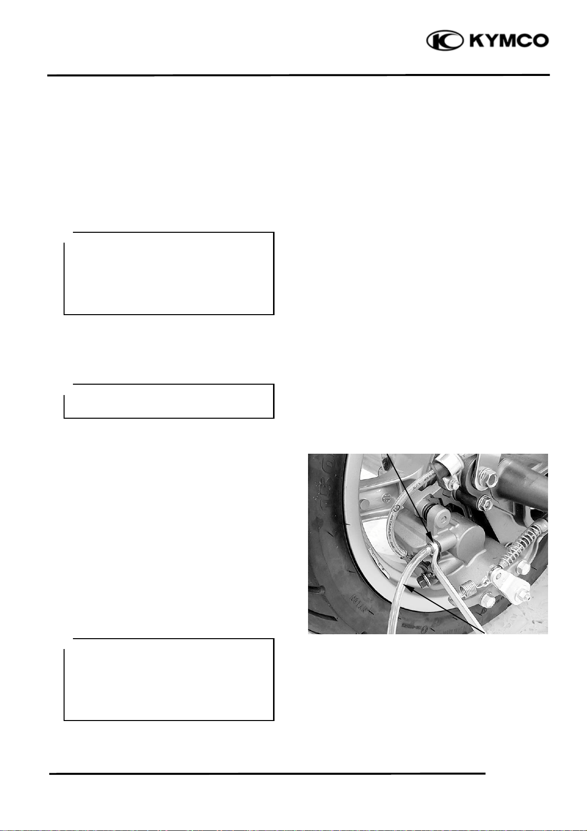
Air bleeding steps (combination brake):
The combination brake system air bleeding is
the same manner as that of the front brake
one.
Bleed the air from the rear side (rear caliper)
and then the front side (right front caliper and
delay valve).
Tighten the bleed screw.
Torque: 6 N•m (0.6 kgf•m, 4.3 lbf•ft)
*
If bleeding is difficult, it may be
necessary to let the brake fluid settle for
a few hours.
Repeat the bleeding procedure when the
tiny bubbles in the system have
disappeared.
Rear Caliper Air Bleed Screw
Clear Hose
16-8
Page 10
16. BRAKE SYSTEM
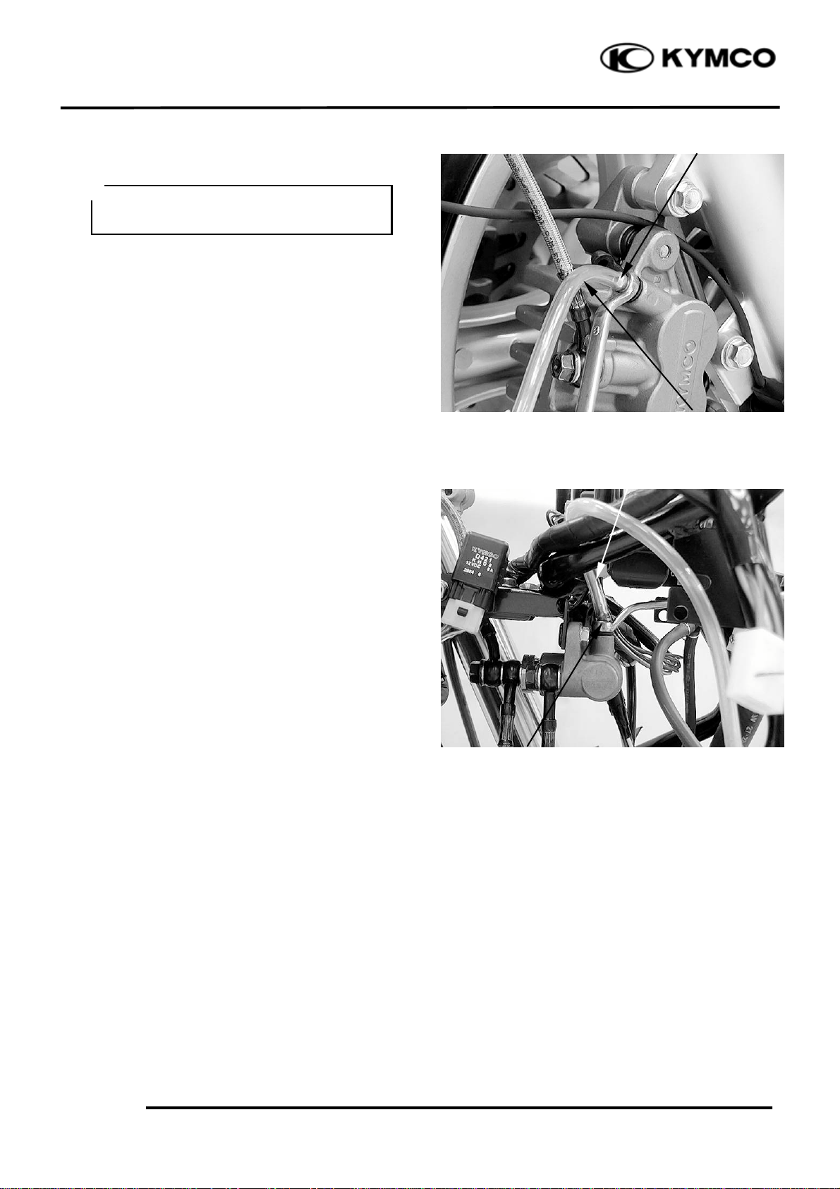
Add brake fluid to the proper level.
*
Check the operation of the brake after
bleeding the brake system.
Install the master cylinder reservoir cap and
diaphragm.
XCITING 500
Right Front Caliper Air Bleed Screw
Clear Hose
Clear Hose
16-9
Relay Valve Air Bleed Screw
Page 11

16. BRAKE SYSTEM
BRAKE PAD
BRAKE PAD REPLACEMENT
Front brake:
Push the caliper pistons all the way in by
pushing the caliper body inward to provide
clearance for new pads.
*
Always replace the brake pads in pairs to
ensure even disc pressure.
XCITING 500
Caliper body
Remove the pad pin plug and loosen the pad
pin.
Remove the pad pin and the brake pads.
Make sure that the pad spring is installed in
original position.
Install new pads so that the their ends rest on
the pad retainer on the bracket properly.
Caliper body
Pad Pin Plug Pad Pin
Pad Pin
Install the pad pin by pushing the pads
against the pad spring to align the pad pin
holes in the pads and caliper.
Brake Pads
16-10
Page 12

16. BRAKE SYSTEM
XCITING 500
Tighten the pad pin to the specified torque.
Torque: 18 N•m (1.8 kgf•m, 13 lbf•ft)
Install the pad pin plug to the specified
torque.
Torque: 3 N•m (0.3 kgf•m, 2.2 lbf•ft)
Rear/Parking brake:
Remove the pad pin plug and loosen the pad
pin.
*
Always replace the brake pads in pairs to
ensure even disc pressure.
Pad Pin Pad Pin Plug
Remove the mount bolts and rear/parking
brake caliper from the rear fork.
Remove the pad pin and brake pads.
16-11
Pad Pin Plug Pad Pin
Rear/Parking Caliper Body Bolts
Page 13

16. BRAKE SYSTEM
Installation steps:
Turn the parking brake caliper piston
clockwise and push it into the parking brake
caliper.
Install the pad pin by pushing the pads
against the pad spring to align the pad pin
holes in the pads and caliper.
XCITING 500
Parking Brake Caliper Piston
Pin
*
Align the pin on the pad with the groove
on the parking brake caliper piston.
Install the rear/parking brake caliper to the
rear fork.
Install and tighten the new rear/parking brake
caliper mounting blots to the specified torque.
Torque: 32 N•m (3.2 kgf•m, 23 lbf•ft)
Groove
Rear/Parking Caliper Body Bolts
16-12
Page 14

16. BRAKE SYSTEM
XCITING 500
Tighten the pad pin to the specified torque.
Torque: 18 N•m (1.8 kgf•m, 13 lbf•ft)
Install the pad pin plug to the specified
torque.
Torque: 3 N•m (0.3 kgf•m, 2.2 lbf•ft)
BRAKE DISC INSPECTION
Visually inspect the brake disc for damage or
cracks.
Measure the brake disc thickness.
Pad Pin Pad Pin Plug
Service limits:Front: 4mm (0.16 in)
Rear: 4mm (0.16 in)
Replace the brake disc if the smallest
measurement is less than the service limit.
Measure the brake disc warpage.
Service limits:0.30 mm (0.012 in)
16-13
Page 15

16. BRAKE SYSTEM
r
XCITING 500
FRONT MASTER CYLINDER
REMOVAL
When removing the brake hose bolt, cover
the end of the hose to prevent contamination.
Secure the hose to prevent fluid from leaking
out.
Remove the upper handlebar cover (page 2-
5).
Drain the front brake hydraulic system (page
16-4).
Remove the two screws and lower handlebar
cover.
Disconnect the brake light connectors from
front master cylinder.
Lower Handlebar Cove
Screws
Remove the brake hose oil bolt, sealing
washers and brake hose eyelet.
Brake Light Switch Connectors
Sealing Washers
Bolt Brake Hose
16-14
Page 16

16. BRAKE SYSTEM
r
t
r
XCITING 500
Remove the bolts from the master cylinder
holder and remove the master cylinder
assembly.
DISASSEMBLY
Remove the brake lever pivot bolt and nut.
Remove the brake lever.
Master Cylinder Bolts
Holde
Nut Brake Leve
Remove the screw and brake light switch.
16-15
Pivot Bol
Brake Light Switch
Screw
Page 17

16. BRAKE SYSTEM
t
r
XCITING 500
ASSEMBLY
Install the brake light switch and tighten the
screw to the specified torque.
Torque: 1 N•m (0.1 kgf•m, 0.7 lbf•ft)
Apply silicone grease to the master piston tip.
Install the brake lever.
Apply silicone grease to the brake lever pivot
bolt sliding surface.
Install and tighten the pivot bolt to the
specified torque.
Brake Light Switch
Screw
Nut Brake Leve
Torque: 6 N•m (0.6 kgf•m, 4.3 lbf•ft)
Install and tighten the pivot nut to the
specified torque.
Torque: 6 N•m (0.6 kgf•m, 4.3 lbf•ft)
INSTALLATION
Align the pin on the master cylinder holder
with the hole on the handlebar.
Pivot Bol
Pin Hole
16-16
Page 18

16. BRAKE SYSTEM
Install the front master cylinders and holders
with the “UP” mark facing up.
Install the bolts and tighten the upper bolt
first then tighten the lower bolt to the
specified torque.
Torque: 12 N•m (1.2 kgf•m, 9 lbf•ft)
Rest the brake hose eyelet against the stopper.
Install the brake hose eyelet with the oil bolt
and new sealing washers.
Tighten the oil bolt to the specified torque.
XCITING 500
Bolts
“UP” Mark
Sealing Washers
Torque: 35 N•m (3.5 kgf•m, 25 lbf•ft)
Connect the brake light switch connectors.
Fill the reservoir to the upper level and bleed
the brake system (page 16-7).
Bolt Brake Hose
16-17
Brake Light Switch Connectors
Page 19

16. BRAKE SYSTEM
r
t
REAR MASTER CYLINDER
REMOVAL
When removing the brake hose bolt, cover
the end of the hose to prevent contamination.
Secure the hose to prevent fluid from leaking
out.
Remove the upper handlebar cover (page 2-
5).
Drain the combination brake hydraulic
system (page 16-5).
Remove the two screws and lower handlebar
cover.
Disconnect the brake light switch connectors
from master cylinder.
XCITING 500
Lower Handlebar Cove
Screws
Remove the brake hose oil bolt, sealing
washers and brake hose eyelet.
Brake Light Switch Connectors
Sealing Washers
Brake Hose Bol
16-18
Page 20

16. BRAKE SYSTEM
t
r
t
t
Remove the bolts from the master cylinder
holder and remove the master cylinder
assembly.
DISASSEMBLY
Remove the brake lever pivot bolt and nut.
Remove the brake lever.
XCITING 500
Holder Master Cylinde
Bol
Brake Lever Nu
Remove the screw and brake light switch.
16-19
Pivot Bol
Screw
Brake Light Switch
Page 21

16. BRAKE SYSTEM
t
t
ASSEMBLY
Install the brake light switch and tighten the
screw to the specified torque.
Torque: 1 N•m (0.1 kgf•m, 0.7 lbf•ft)
XCITING 500
Screw
Brake Light Switch
Apply silicone grease to the master piston tip.
Install the brake lever.
Apply silicone grease to the brake lever pivot
bolt sliding surface.
Install and tighten the pivot bolt to the
specified torque.
Torque: 6 N•m (0.6 kgf•m, 4.3 lbf•ft)
Install and tighten the pivot nut to the
specified torque.
Torque: 6 N•m (0.6 kgf•m, 4.3 lbf•ft)
INSTALLATION
Align the pin on the master cylinder holder
with the hole on the handlebar.
Brake Lever Nu
Pivot Bol
Hole Pin
16-20
Page 22

16. BRAKE SYSTEM
t
r
t
Install the rear master cylinders and holders
with the “UP” mark facing up.
Install the bolts and tighten the upper bolt
first then tighten the lower bolt to the
specified torque.
Torque: 12 N•m (1.2 kgf•m, 9 lbf•ft)
XCITING 500
“UP” Mark Master Cylinde
Bol
Rest the brake hose eyelet against the stopper.
Install the brake hose eyelet with the oil bolt
and new sealing washers.
Tighten the oil bolt to the specified torque.
Torque: 35 N•m (3.5 kgf•m, 25 lbf•ft)
Connect the brake light switch connectors.
Fill the reservoir to the upper level and bleed
the brake system (page 16-8).
Sealing Washers
Brake Hose Bol
16-21
Brake Light Switch Connectors
Page 23

16. BRAKE SYSTEM
DELAY VAVLE
REMOVAL
When removing the brake hose bolt, cover
the end of the hose to prevent contamination.
Secure the hose to prevent fluid from leaking
out.
Remove the front cover (page 2-11).
Drain the combination brake hydraulic
system (page 16-5).
Remove the brake hose oil bolt, sealing
washers and brake hose eyelets.
Remove the two nuts and delay valve.
XCITING 500
Sealing Washers Sealing Washers
Bolts Brake Hose
Nuts
Delay Valve
16-22
Page 24

16. BRAKE SYSTEM
XCITING 500
INSTALLATION
Install the delay valve and tighten the nuts
securely.
Install the brake hose eyelets and new sealing
washers.
Tighten the brake hose bolt to the specified
torque while rest the brake hose eyelet
against the stopper on the delay valve.
Nuts
Delay Valve
Sealing Washers Sealing Washers
Torque: 35 N•m (3.5 kgf•m, 25 lbf•ft)
Fill the reservoir to the upper level and bleed
the brake system (page 16-8).
Bolts Brake Hose
16-23
Page 25

16. BRAKE SYSTEM
r
r
FRONT BRAKE CALIPER
REMOVAL
Drain the front brake hydraulic system (left
front brake caliper: page 16-4) or
combination brake hydraulic system (right
front brake caliper: page 16-5).
Remove the brake pads (page 16-10).
Remove the oil bolts, sealing washers and
brake hose from the brake caliper.
Remove the mount bolts and front brake
caliper.
XCITING 500
Brake Hose
Bolts Sealing Washers
Bolts
DISASSEMBLY
Remove pad spring from the caliper body.
*
Do not remove the retainer from the
bracket unless replacement.
Brake Calipe
Sealing Washers Sealing Washers
Pad Spring Retaine
16-24
Page 26

16. BRAKE SYSTEM
t
r
XCITING 500
Remove the caliper bracket from the caliper
body.
*
Do not remove the caliper and bracket
pins unless replacement.
ASSEMBLY
Apply silicone grease to the boots inside.
Install the caliper bracket to the caliper.
Install the pad spring into the caliper body as
shown.
Boots Bracke
Bolts Brake Hose
Pad Spring
INSTALLATION
Install the front caliper onto the fork leg.
Install and tighten the new front caliper
mount bolts to the specified torque.
Torque: 32 N•m (3.2 kgf•m, 23 lbf•ft)
16-25
Bolts Brake Hose
Bolts
Brake Calipe
Page 27

16. BRAKE SYSTEM
XCITING 500
Install the brake hose eyelet to the caliper
body with new sealing washers and oil bolts.
Push the brake hose eyelet to the stopper on
the caliper, then tighten the oil bolts to the
specified torque.
Torque: 35 N•m (3.5 kgf•m, 25 lbf•ft)
Install the brake pads (page 16-10).
Fill and bleed the hydraulic system (page 16-
7 or page 16-8).
REAR/PARKING BRAKE
CALIPER
REMOVAL
Remove the muffler (page 2-15).
Drain the rear brake hydraulic system (page
16-5).
Brake Hose
Bolts Sealing Washers
Disconnect the parking brake cable from the
brake arm.
Remove the pad pin plug and loosen the pad
pin.
Remove the brake pad (page 16-11).
Remove the oil bolt, sealing washers and
brake hose from the brake caliper.
Arm Brake Cable
Brake Hose
Bolts Sealing Washers
16-26
Page 28

16. BRAKE SYSTEM
t
r
XCITING 500
Remove the mount bolts and rear/parking
brake caliper from the rear fork.
DISASSEMBLY (REAR BRAKE)
Remove the pad spring from the caliper body.
*
Do not remove the retainer from the
bracket unless replacement.
Rear/Parking Brake Caliper Bolts
Brake Hose
Remove the caliper bracket from the caliper
body.
*
Do not remove the caliper and bracket
pins unless replacement.
ASSEMBLY (REAR BRAKE)
Apply silicone grease to the boot inside.
Apply silicone grease to the boot inside.
Install the caliper bracket to the caliper.
16-27
Pad Spring Retaine
Bracke
Boots
Page 29

16. BRAKE SYSTEM
t
m
XCITING 500
Install the pad spring into the caliper body as
shown.
DISASSEMBLY (PARKING BRAKE)
Remove the lock nut and parking brake arm.
Pad Spring
Brake Ar
Remove the parking brake shaft and push rod.
Lock Nu
Brake Shaft Push Rod
16-28
Page 30

16. BRAKE SYSTEM
t
t
t
Removed the two bolts, gasket and parking
brake bracket.
ASSEMBLY (PARKING BRAKE)
Install the gasket.
XCITING 500
Bolts
Bracke
Gaske
Install the parking brake bracket and tighten
the bolts to the specified torque.
Torque: 32 N•m (3.2 kgf•m, 23 lbf•ft)
Apply silicone grease to the parking brake
shaft rolling surface.
Install the parking brake shaft.
16-29
Brake Shaf
Page 31

16. BRAKE SYSTEM
t
m
Temporarily install the brake arm and the
lock nut.
INSTALLATION
Install the brake pads (page 16-12).
XCITING 500
Brake Ar
Lock Nu
Rear/Parking Brake Caliper Bolts
Install the rear/parking brake caliper to the
rear fork and tighten the new mount bolts to
specified torque.
Torque: 32 N•m (3.2 kgf•m, 23 lbf•ft)
Install the brake hose eyelet to the caliper
body with new sealing washers and oil bolts.
Push the brake hose eyelet to the stopper on
the caliper, then tighten the oil bolts to the
specified torque.
Torque: 35 N•m (3.5 kgf•m, 25 lbf•ft)
Fill and bleed the hydraulic system (page 16-
8).
Brake Hose
Bolts Sealing Washers
16-30
Page 32

16. BRAKE SYSTEM
m
r
t
XCITING 500
Connect the parking brake cable.
Adjust the parking brake (page 3- 21).
PARKING BRAKE LEVER LINK
REMOVAL
Remove the inner cover (page 2-14).
Ar
Brake Cable
Brake Cable
Loosen the lock nut and disconnect the
parking brake cable from the parking braking
brake lever link.
Disconnect the parking brake switch
connector.
Lock Nu
16-31
Parking Brake Switch Connecto
Page 33

16. BRAKE SYSTEM
XCITING 500
Remove the two nuts and parking brake lever
link.
DISASSEMBLY
Remove the two screws and parking brake
switch.
Parking Brake Lever Link
Nuts
Parking Brake Switch
ASSEMBLY
Assembly is in the reverse order of
disassembly.
INSTALLATION
Installation is in the reverse order of removal.
Screw
16-32
 Loading...