

Page 1

1. GENERAL INFORMATION
XCITING 500
1
__________________________________________________________________________________
__________________________________________________________________________________
__________________________________________________________________________________
__________________________________________________________________________________
__________________________________________________________________________________
GENERAL INFORMATION
1
__________________________________________________________________________________
SERIAL NUMBER------------------------------------------------------------ 1-1
SPECIFICATIONS------------------------------------------------------------ 1-2
SERVICE PRECAUTIONS-------------------------------------------------- 1-3
TORQUE VALUES ----------------------------------------------------------- 1-7
SPECIAL TOOLS ------------------------------------------------------------- 1-9
LUBRICATION POINTS ---------------------------------------------------1-10
CA B L E & HA R N E S S R O UTI N G--------------------------------------------1-12
TROUBLESHOOTING------------------------------------------------------1-22
1-0
Page 2
1. GENERAL INFORMATION
r
r
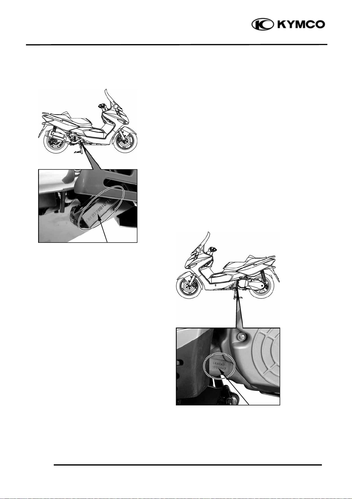
SERIAL NUMBER
XCITING 500
Location of Frame Serial Numbe
Location of Engine Serial Numbe
1-1
Page 3
1. GENERAL INFORMATION
r
m
g
r
m
m
y
r
g
y
y
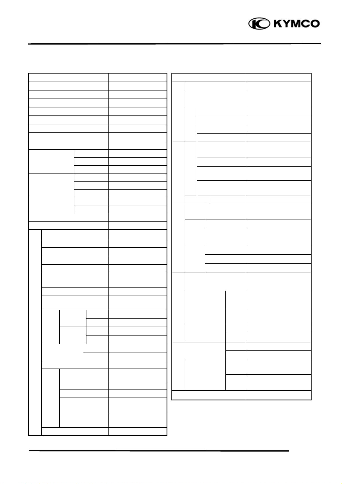
SPECIFICATIONS
XCITING 500
ITEM SPECIFICATIONS
Name XCITING 500
Overall length 2250 mm (90 in)
Overall width (mm) 815 mm (33 in)
Overall height (mm) 1450 mm (58 in)
Wheel base (mm) 1570 mm (63 in)
Engine type O.H.C.
Displacement 498.5 cm3 (30.4 cu-in)
Fuel Used 92# nonleaded gasoline
Front wheel 83 kg (183 lbs)
Dry weight Rear wheel 132 kg (290 lbs)
Total 215 kg (473 lbs)
Front wheel 90 kg (198 lbs)
Curb weight Rear wheel 141 kg (310 lbs)
Total 231 kg (508 lbs)
Tires
Ground clearance 150 mm (6 in)
Min. turning radius 2750 mm (110 in)
Starting system
Type Gasoline, 4-stroke
Cylinder arrangement Single cylinder
Combustion chamber type Semi-sphere
Valve arrangement O.H.C., chain drive
Bore x stroke (mm)
Compression ratio 10.5:1
Compression pressure
Engine
Valve
timin
Valve clearance
(cold)
Idle speed (rpm) 1400rpm
Lubrication
S
stem
Cooling Type Liquid cooled
Front wheel 120/70-15
Rear wheel 150/70-14
Electric starter moto
92 x 75 mm
(3.7 x 3 in)
13 kgf/c
185 psi)
Intake
Exhaust
Lubrication type
Oil pump type Trochoid
Oil filter type Full-flow filtration
Oil capacity
Final reduction oil
capacity
Open 2° BTDC
Close 45° ABDC
Open 45° BBDC
Close 5° ATDC
Intake 0.1 mm (0.004 in)
Exhaust 0.1 mm (0.004 in)
Forced pressure &
Wet sump
2.5 L (2.2 lmp qt,
2.65 Us qt)
0.55 L (0.5 lmp qt,
0.58 Us qt)
² (1300kPa,
ITEM SPECIFICATIONS
Air cleaner type & No Wet paper type element
Fuel S
Fuel capacity 12.8 L (3.38 lmp gal,
Carbureto
stem
Electrical Equipment
Power Drive System
Moving Device
Brake syste
type
Damping
Device
Frame type Back born
Type CVK
Main jet NO. 98
Venturi dia. φ36 mm (φ1.44 in)
Throttle type PISTON
I
Type
nition S
Spark plug CR8E
stem
Ignition timing Throttle position senso
Spark plug gap 0.6~0.7mm (0.002~
Battery Capacity 12V12AH
Clutch
Ratio
FR/RR tire rolling
circumference
Tire pressure
(rider only/60
kg)
Turning Left 40°
angle
Suspension
type
Type Dry, centrifugal
Transmis-
sion Gear
Type Helical gear/spur gear
Operation
Reduction
Type CVT
Preliminary
Final
Front
Rear
Right 40°
RearDisk brake
Front Disk brake
Front
Rear
2.82 US gal
Full transistor digital
ignition
0.003 in)
automatic
Automatic centrifugal
Type
2.68 – 1
5.4
1724/1778 mm (69/71 in)
2 kg/cm² (200 Kpa, 28
psi)
2.5 kg/c
psi)
Telescopic fork
Unit swing
² (250 Kpa, 36
1-2
Page 4
1. GENERAL INFORMATION
XCITING 500
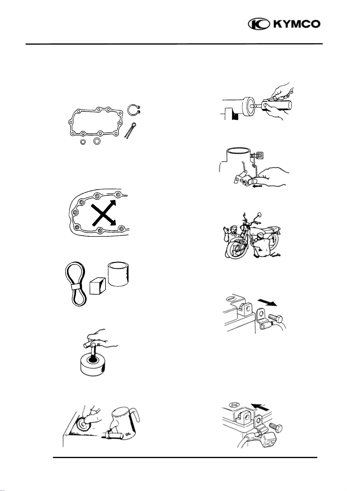
SERVICE PRECAUTIONS
Make sure to install new gaskets, O-rings,
circlips, cotter pins, etc. when
reassembling.
When tightening bolts or nuts, begin with
larger-diameter to smaller ones at several
times, and tighten to the specified torque
diagonally.
Apply or add designated greases and
lubricants to the specified lubrication
points.
After reassembly, check all parts for proper
tightening and operation.
When two persons work together, pay
attention to the mutual working safety.
Use genuine parts and lubricants.
When servicing the motorcycle, be sure to
use special tools for removal and
installation.
After disassembly, clean removed parts.
Lubricate sliding surfaces with engine oil
before reassembly.
Disconnect the battery negative (-) terminal
before operation.
When using a spanner or other tools, make
sure not to damage the motorcycle surface.
After operation, check all connecting
points, fasteners, and lines for proper
connection and installation.
When connecting the battery, the positive
(+) terminal must be connected first.
After connection, apply grease to the
battery terminals.
Terminal caps shall be installed securely.
1-3
Page 5
1. GENERAL INFORMATION
m
XCITING 500
If the fuse is burned out, find the cause and
repair it. Replace it with a new one
according to the specified capacity.
Confir
Capacity
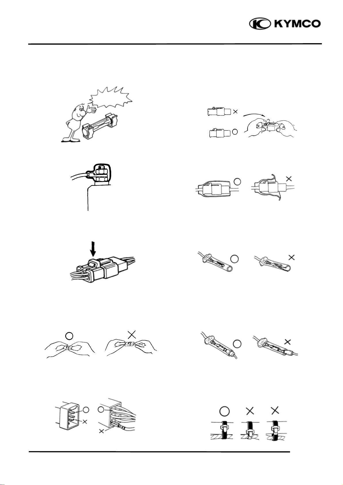
After operation, terminal caps shall be
installed securely.
When taking out the connector, the lock on
the connector shall be released before
operation.
The connector shall be inserted
completely.
If the double connector has a lock, lock
it at the correct position.
Check if there is any loose wire.
Before connecting a terminal, check for
damaged terminal cover or loose negative
terminal.
Check the double connector cover for
proper coverage and installation.
Hold the connector body when connecting
or disconnecting it.
Do not pull the connector wire.
Check if any connector terminal is bending,
protruding or loose.
Insert the terminal completely.
Check the terminal cover for proper
coverage.
Do not make the terminal cover opening
face up.
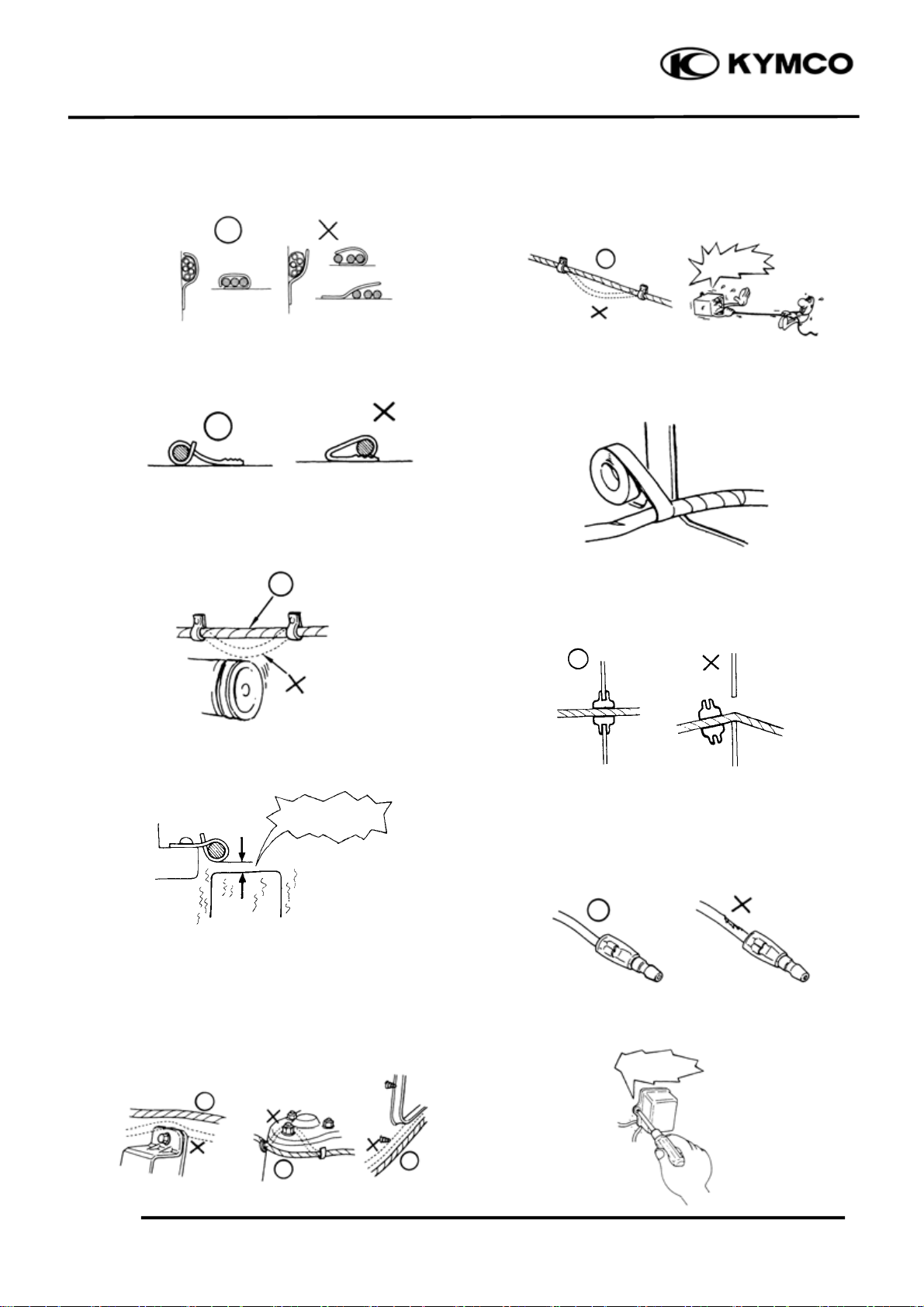
Secure wire harnesses to the frame with
their respective wire bands at the
designated locations.
Tighten the bands so that only the insulated
surfaces contact the wire harnesses.
1-4
Page 6
1. GENERAL INFORMATION
N
t
XCITING 500
After clamping, check each wire to make
sure it is secure.
Do not squeeze wires against the weld or
its clamp.
After clamping, check each harness to
make sure that it is not interfering with any
moving or sliding parts.
Route harnesses so they are neither
pulled tight nor have excessive slack.
Do not pull
too tight!
Protect wires and harnesses with electrical
tape or tube if they contact a sharp edge or
corner.
When rubber protecting cover is used to
protect the wire harnesses, it shall be
installed securely.
When fixing the wire harnesses, do not
make it contact the parts which will
generate high heat.
o Contac
Route wire harnesses to avoid sharp edges
or corners. Avoid the projected ends of
bolts and screws.
Route wire harnesses passing through the
side of bolts and screws. Avoid the
projected ends of bolts and screws.
Do not break the sheath of wire.
If a wire or harness is with a broken sheath,
repair by wrapping it with protective tape
or replace it.
When installing other parts, do not press or
squeeze the wires.
Do not press or
squeeze the
1-5
Page 7
1. GENERAL INFORMATION
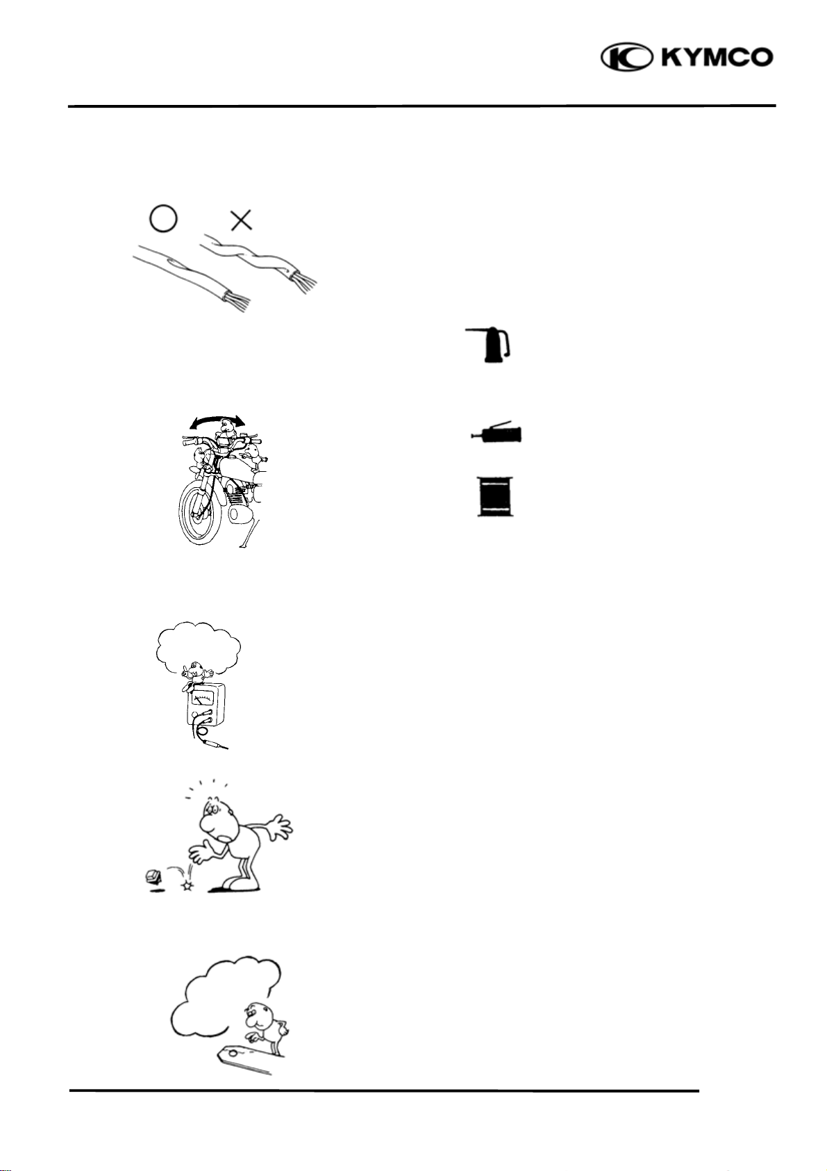
After routing, check that the wire harnesses
are not twisted or kinked.
XCITING 500
Symbols:
The following symbols represent the
servicing methods and cautions included in
this service manual.
Wire harnesses routed along with
handlebar should not be pulled tight, have
excessive slack or interfere with adjacent
or surrounding parts in all steering
positions.
When a testing device is used, make sure to
understand the operating methods
thoroughly and operate according to the
operating instructions.
Do you understand
the instrument?
Engine Oil
Grease
Gear Oil
*
: Apply engine oil to the
specified points. (Use
designated engine oil for
lubrication.)
: Apply grease for lubrication.
: Transmission Gear Oil (90#)
: Note
Be careful not to drop any parts.
When rust is found on a terminal, remove
the rust with sand paper or equivalent
before connecting.
Remove Rust!
1-6
Page 8
1. GENERAL INFORMATION
TORQUE VALUES
STANDARD TORQUE VALUES
XCITING 500
Item
5mm bolt and nut
6mm bolt and nut
8mm bolt and nut
10mm bolt and nut
12mm bolt and nut
14mm bolt and nut
Torque specifications listed below are for important fasteners.
ENGINE
Item Q‘ty
MAINTENANCE:
Engine oil drain plug
Oil strainer screen cap
Oil filter cartridge
Transmission oil drain bolt
Transmission oil filler bolt
Spark plug
Tappet adjust nut
LUBRICATION SYSTEM:
Oil pump screw
Oil cooler bolt
COOLING SYSTEM:
Water pump cover bolt
CYLINDER HEAD:
Breather separator bolt
Cylinder head bolt (1 – 4)
Cylinder head bolt (5 – 13)
Cylinder head cover bolt
Cam chain tensioner bolt
Tensioner pivot bolt
Rocker arm shaft
DRIVE/DRIVEN PULLEY:
Drive face nut
Clutch out nut
Torque
N•m (kgf•m, lbf•ft)
5(0.5, 4)
10 (1, 7)
22 (2.2, 16)
35 (3.5, 25)
55 (5.5, 40)
70 (7, 50)
Thread dia.
1
1
1
1
1
1
4
1
2
2
3
4
9
4
2
1
2
1
1
Item
4mm screw
5mm screw
6mm screw, SH bolt
6mm flange bolt and nut
8mm flange bolt and nut
10mm flange bolt and nut
(mm)
12
30
20
8
8
10
5
4
16
6
6
10
8
6
6
8
18
18
14
N•m (kgf•m, lbf•ft)
Torque
25 (2.5, 18)
15 (1.5, 11)
10 (1, 7)
24 (2.4, 18)
24 (2.4, 18)
12 (1.2, 9)
9 (0.9, 6)
3 (0.3, 2)
35 (3.5, 25)
13 (1.3, 9)
13 (1.3, 9)
48 (4.8, 35)
23 (2.3, 17)
10 (1, 7)
12 (1.2, 9)
10 (1, 7)
45 (4.5, 32)
135 (13.5, 97)
80 (8, 58)
Torque
N•m (kgf•m, lbf•ft)
3 (0.3, 2)
4 (0.4, 3)
9 (0.9, 6.5)
12 (1.2, 9)
27 (2.7, 20)
40 (4, 29)
Remarks
Apply oil
Apply oil
Apply oil
Apply oil
Apply oil
Apply oil
1-7
Page 9
1. GENERAL INFORMATION
ENGINE (Cont’d)
XCITING 500
Item Q‘ty
Drive plate nut
ALTERNATOR
ACG flywheel nut
FINAL REDUCTION:
Transmission cover bolt
CRANKCASE:
Crankcase bolt
Oil pipe bolt
Cam chain guide
SWITCH:
Oil pressure switch
FRAME
Item Q‘ty Thread dia.(mm)
1
1
8
13
2
2
1
Thread dia.
(mm)
28
14
8
6
16
8
PT 1/8
Torque
N•m (kgf•m, lbf•ft)
78 (7.8, 56)
55 (5.5, 40)
27 (2.7, 20)
12 (1.2, 9)
43 (4.3, 31)
20 (2, 15)
22 (2.2, 16)
Torque
N•m (kgf•m,
lbf•ft)
Remarks
Apply oil
Apply oil
Apply seal
Remarks
STEERING:
Handlebar bolt
Upper pinch bolt
Lower pinch bolt
Bridge stem nut
Steering stem lock nut
Top thread
WHEEL:
Front axle bolt
Front fork bolt
Rear axle nut
SUSPENSION:
Rear shock absorber bolt
Rear fork
BRAKE:
Front caliper mounting bolt
Rear caliper mounting bolt
4
2
4
1
1
1
1
2
1
4
2
4
2
8
8
8
22
26
26
18
8
20
10
8
8
8
23 (2.3, 17)
23 (2.3, 17)
23 (2.3, 17)
62 (6.2, 45)
45 (4.5, 32)
17 (1.7, 12)
55 (5.5, 40)
23 (2.3, 17)
180 (18, 130)
40 (4, 29)
32 (3.2, 23)
32 (3.2, 23)
32 (3.2, 23)
Replace a new one
Replace a new one
Brake fluid bolt
Master cylinder bolt
6
4
10
6
35 (3.5, 25)
12 (1.2, 9)
1-8
Page 10
1. GENERAL INFORMATION
FRAME (Cont’d)
Item Q‘ty Thread dia.(mm)
ENGINE HANGER:
Torque
N•m (kgf•m,
lbf•ft)
XCITING 500
Remarks
Engine hanger bolt
Engine mounting bolt
Engine mounting nut
Engine hanger rod nut
MUFFLER
Exhaust pipe nut
Muffler mount bolt
4
1
1
1
2
3
SPECIAL TOOLS
Tool Name Tool No. Remarks
Clutch spring compressor
Bearing puller 10,12,15,18mm E037
Valve spring compressor E040
Oil seal & bearing installer E014
Tappet adjuster E036
Flywheel puller E054
Universal holder E017
Oil filter cartridge wrench E052
Flywheel holder E021
Lock nut socket wrench F002
E053 Clutch disassembly
10
14
14
10
8
10
Bearing removal
Valve removal
Oil seal & bearing install
Tappet adjustment
A.C. generator flywheel removal
Holding clutch for removal
Cartridge removal or install
A.C. generator flywheel holding
Steering stem removal or install
50 (5, 36)
80 (8, 58)
80 (8, 58)
35 (3.5, 25)
20 (2, 14)
35 (3.5, 25)
1-9
Page 11

1. GENERAL INFORMATION
LUBRICATION POINTS
ENGINE
Lubrication Points Lubricant
XCITING 500
Valve guide/valve stem movable part
Camshaft protruding surface
Valve rocker arm friction surface
Camshaft drive chain
Cylinder lock bolt and nut
Piston surroundings and piston ring grooves
Piston pin surroundings
Cylinder inside wall
Connecting rod/piston pin hole
Connecting rod big end
Crankshaft
Balancer shaft
Crankshaft one-way clutch movable part
Oil pump drive chain
Starter reduction gear engaging part
O-ring face
Oil seal lip
•Genuine KYMCO Engine Oil (SAE 5W-50)
•API SJ Engine Oil
Drive gear shaft
Countershaft
Final gear
Final gear shaft
Transmission gearshaft bearing part
A.C. generator connector Adhesive
Transmission oil: SAE 90
1-10
Page 12

1. GENERAL INFORMATION
k
FRAME
The following is the lubrication points for the frame.
Use general purpose grease for parts not listed.
Apply clean engine oil or grease to cables and movable parts not specified. This will avoid
abnormal noise and rise the durability of the motorcycle.
XCITING 500
Seat Loc
Grease
Engine Oil
Throttle Cable
Grease
Front/Rear Brake Lever Pivot
Rear Wheel Bearing
1-11
Front Wheel Bearing
Grease
Grease
Center Stand/Side Stand Pivot
Grease
Page 13

1. GENERAL INFORMATION
CABLE & HARNESS ROUTING
XCITING 500
1-12
Page 14

1. GENERAL INFORMATION
XCITING 500
1-13
Page 15

1. GENERAL INFORMATION
XCITING 500
1-14
Page 16

1. GENERAL INFORMATION
XCITING 500
1-15
Page 17

1. GENERAL INFORMATION
XCITING 500
1-16
Page 18

1. GENERAL INFORMATION
XCITING 500
1-17
Page 19

1. GENERAL INFORMATION
XCITING 500
1-18
Page 20

1. GENERAL INFORMATION
XCITING 500
1-19
Page 21

1. GENERAL INFORMATION
XCITING 500
1-20
Page 22

1. GENERAL INFORMATION
XCITING 500
1-21
Page 23

1. GENERAL INFORMATION
t
t
r
p
t
TROUBLESHOOTING
ENGINE WILL NOT START OR IS HARD TO START
XCITING 500
Inspection/Adjustment
Check if fuel reaches
carburetor by loosening
drain screw
Remove spark plug and
install it into spark plug
cap to test spark by
connecting it to engine
ground
Test cylinde
compression
Start engine by following normal starting
rocedure
Fuel reaches
carburetor
Spark jumps
Normal
compression
Engine does no
fire
Symptom
Fuel does no
reach carburetor
Weak or no spark
Low or no
compression
Engine fires bu
does not start
Probable Cause
cEmpty fuel tank
dClogged carburetor fuel inlet
tube, vacuum tube or fuel tube
eClogged auto fuel valve
fClogged float oil passage
gClogged fuel tank cap
breather hole
hClogged fuel strainer
iClogged fuel filter
jFaulty fuel pump
cFaulty spark plug
dFouled spark plug
eFaulty ignition unit
fFaulty A.C. generator
gBroken or shorted ignition coil
hBroken or shorted exciter coil
iFaulty ignition switch
cStarter motor idles but
crankshaft does not rotate
dValve clearance too small
eImproper valve and seat contact
fWorn cylinder and piston rings
gBlown cylinder head gasket
hFlaws in cylinder head
iSeized valve
jImproper valve timing
cFaulty auto bystarter
dAir leaking through intake
pipe
eIncorrect ignition timing
fIncorrectly adjusted pilot screw
Remove spark plug and
inspect again
Dry spark plug
Wet spark plug
cFlooded carburetor
dFaulty auto bystarter
eThrottle valve excessively
open
1-22
Page 24

1. GENERAL INFORMATION
g
y
g
r
g
t
t
t
N
N
pip
t
t
r
r
t
r
prop
y
t
y
ENGINE LACKS POWER
XCITING 500
Inspection/Adjustment
Start engine and
accelerate lightly for
Check ignition timing
(using a timing light)
Check valve clearance
Test cylinder compression
Check carburetor fo
clogging
Engine speed
Correct timin
Correc
ormal
compression
ot Clogged
Symptom
Engine speed does
not increase
sufficientl
Abnormal
compression
Incorrect timin
Incorrec
Clogged
Probable Cause
cClogged air cleaner
dRestricted fuel flow
eClogged fuel line between fuel
tank and carburetor
fClogged exhaust muffler
gFaulty auto bystarter
hSplit carburetor vacuum piston
diaphragm
cFaulty
dFaulty A.C. generator
cImproper valve clearance
dWorn valve seat (valve stem too
cImproper valve and seat contact
dWorn cylinder and piston rings
eBlown cylinder head gasket
fFlaws in cylinder head
gImproper valve timing
cClogged carburetor jets
ignition unit
adjustment
protruding
Remove spark plug and
inspec
Remove oil dipstick and
check oil level and condition
Remove cylinder head oil
e bolt and inspec
Check if engine overheats
Rapidly accelerate or run
h speed
at hi
Plug not fouled o
Correct and no
Valve train lubricated
erl
Engine does no
overheats
Engine does not knock
Plug fouled o
Incorrect o
Valve train no
lubricated properl
Engine overheats
Engine knocks
cFouled spark plug
dIncorrect heat range plug
cOil level too high
dOil level too low
eOil not changed
cClogged oil pipe
dFaulty oil pump
cInsufficient coolant
dFaulty thermostat
eWorn cylinder and piston rings
fMixture too lean
gPoor quality fuel
hExcessive carbon buildup in
combustion chamber
iIgnition timing too early
jAir in cooling system
cExcessive carbon build-up in
combustion chamber
dPoor quality fuel
eClutch slipping
fMixture too lean
g Ignition timing too early
1-23
Page 25

1. GENERAL INFORMATION
g
r
t
t
POOR PERFORMANCE (ESPECIALLY AT IDLE AND LOW SPEEDS)
Inspection/Adjustment Symptom Probable Cause
Check ignition timing
XCITING 500
Check carburetor pilo
screw adjustment
Check carburetor gaske
for air leaks
Remove spark plug and
install it into spark plug
cap to test spark by
connecting it to engine
round
Check carburetor ai
cut-off valve
Correct timing
Correctly adjusted
No air leak
Good spark
Incorrect timing
Incorrectly adjusted
Air leaks
Weak or inter-
mittent spark
cFaulty ignition unit
dFaulty A.C. generator
cMixture too rich (turn screw
out)
dMixture too lean (turn screw
in)
cDamaged insulator rubber
dCarburetor not securely
tightened
eFaulty intake manifold gasket
fDeformed carburetor O-ring
cFaulty or fouled spark plug
dFaulty ignition unit
eFaulty A.C. generator
fFaulty ignition coil
gBroken or shorted high
tension wire
hFaulty ignition switch
Good
Faulty
cDamaged air cut-off valve
diaphragm
dDamaged air cut-off valve
spring
1-24
Page 26

1. GENERAL INFORMATION
r
t
t
POOR PERFORMANCE (AT HIGH SPEED)
Inspection/Adjustment Symptom Probable Cause
Check ignition timing
XCITING 500
Check valve clearance
Check fuel pump fo
fuel supply
Check carburetor jets
for clogging
Correct timing
Correctly adjusted
Fuel flows freely
Not clogged
Incorrect timing
Incorrectly adjusted
Fuel flow restricted
Clogged
cFaulty ignition unit
dFaulty A.C. generator
cImproperly adjusted valve
clearance
dWorn valve seat
cEmpty fuel tank
dClogged fuel tube or filter
eFaulty fuel pump
fCracked
tube
cClean and unclog
fuel pump vacuum
Check valve timing
Check valve spring
tension
1-25
Correc
Not weakened
Incorrec
Weak spring
cCam timing gear aligning
marks not aligned
cFaulty spring
Page 27

1. GENERAL INFORMATION
ENGINE NOISE
XCITING 500
Symptom
Valve noise
Piston noise
Cam chain noise
Probable Cause
cValve clearance too large
dWorn camshaft lobe
cWorn piston rings
dWorn piston pin and connecting rod small
end
eExcessive carbon build-up in combustion
chamber
cDamaged cam chain tensioner
dWorn cam gear teeth
eWorn or damaged cam chain
fExtended cam chain
Crankshaft noise
Gear noise
cFaulty crankshaft bearing
dWorn crank pin bearing
cWorn or damaged final reduction gears
dWorn final reduction gear shaft splines
1-26
Page 28

1. GENERAL INFORMATION
t
)
t
r
CLUTCH, DRIVE AND DRIVEN PULLEYS
XCITING 500
Symptom
Engine starts but motorcycle does not move
Motorcycle creeps o
engine starts but soon
stops or seems to rush
out (Rear wheel rotates
when engine idles)
Engine lacks power a
start of a grade(poor
slope performance
Probable Cause
cWorn or slipping drive belt
dBroken ramp plate
eBroken drive face spring
fSeparated clutch lining
gDamaged driven pulley shaft splines
hDamaged final gear
iSeized final gear
cBroken shoe spring
dClutch outer and clutch weight stuck
eSeized pivot
cWorn or slipping drive belt
dWorn weight rollers
eSeized drive pulley bearings
fWeak driven face spring
gWorn or seized driven pulley bearings
1-27
Engine lacks power a
high speed
There is abnormal noise
or smell while running
cWorn or slipping drive belt
dWorn weight rollers
eWorn or seized driven pulley bearings
cOil or grease fouled drive belt
dWorn drive belt
eWeak driven face spring
fWorn or seized driven pulley bearings
Page 29

1. GENERAL INFORMATION
t
t
t
m
m
m
pplying
t
t
g
t
g
n
b
r
r
r
r
prop
y
n
t
STARTER MOTOR
1. Starter motor won‘t turn
XCITING 500
Inspection/Adjustmen
Check operation of
stop switch by
a
Check battery circui
by operating turn
si
Check operation of
starter relay by
depressing starter
utton
Connect starte
motor directly to
battery
brake
Stoplight comes on
nals
Signals operate
properly
Relay operates
properly
Starter motor turns
2. Starter motor turns slowly or idles
Sympto
Stoplight does no
come on
Signals dim, remai
on or don‘t operate
Relay does no
operate
Starter does not turn
Probable Cause
cBurned out fuse
dWeak or dead battery
eFaulty stop switch
fLoose or disconnected
connectors
gBroken or shorted ignition
switch wire
cFaulty or weak battery
cPoor starter button connection
dOpen or shorted starter relay
eLoose or disconnected
connectors
cWorn brushes
dOpen or shorted wires or rotor
eOpen starter motor cable
fLoose connectors
cOpen wire harness
Inspection/Adjustmen
Check battery circui
by operating turn
nals
si
Signals operate
erl
Connect starte
motor directly to
battery
Rotate crankshaft
Starter moto
turns slowly
Turns easily
3. Starter motor does not stop turning
Inspection/Adjustmen
Turn ignition switch
OFF
Sympto
Sympto
Signals dim, remai
on or don‘t operate
Starter moto
turns normally
Hard to turn
Probable Cause
cWeak or dead battery
cLoose connector or terminal
dPoor contact in starter relay
eFaulty starter clutch
cSeized cylinder
cBroken or shorted starter
motor cable
Probable Cause
Not stopped
Stopped
cFaulty starter pinion
cStarter relay shorted or stuck
closed
1-28
Page 30

1. GENERAL INFORMATION
g
g
r
r
NO SPARK AT SPARK PLUG
XCITING 500
Inspection/Adjustment Symptom
Replace with a new
spark plug and inspect
ain
a
Weak or no spark
Check spark plug cap
and high-tension wire
for looseness
Not loose
Check ignition unit
coupler for looseness
Good
Measure resistance
between terminals of
nition unit couple
i
Good spark
Loose
Good
Probable Cause
cFaulty spark plug
cFaulty spark plug
cPoorly connected coupler
Check related parts
Check ignition unit
with a ignition unit
teste
Check ignition coil with
a ignition unit tester
Normal
Normal
Normal
Abnormal
Abnormal
Abnormal
Abnormal
cFaulty ignition switch
dFaulty exciter coil
eFaulty pulser coil
fFaulty ignition coil
cBroken wire harness
dPoorly connected coupler
cFaulty ignition unit
cFaulty ignition coil
1-29
Page 31

1. GENERAL INFORMATION
t
t
r
t
POOR CHARGING (BATTERY OVER DISCHARGING OR OVERCHARGING)
Undercharging
XCITING 500
Inspection/Adjustment
Start engine and tes
limit voltage of battery
terminals
Measure resistance
between AC generator
coil terminals
Test output voltage of
regulator/rectifier
coupler red wire
Normal voltage
Normal
Normal voltage
Symptom
Voltage does no
Resistance too low
No voltage
Probable Cause
cFaulty AC generator
dFaulty regulator/rectifier
eFaulty battery
cShorted AC generator coil
dOpen circuit between AC
generator 3 yellow wires
cFaulty regulator/rectifier
dFaulty AC generator
eLoose regulator/rectifier
coupler
fLimit voltage too high
Overcharging
Inspection/Adjustment
Measure battery limi
voltage with an electric
teste
Check resistance
between regulator/
rectifier terminals
Normal
Normal
Symptom
Abnormal
Abnormal
Probable Cause
cFaulty battery
dFaulty regulator/rectifier
eBroken or poorly connected
regulator/rectifier black wire
cLimit voltage too high
1-30
Page 32

1. GENERAL INFORMATION
p
t
p
t
prop
y
n
prop
y
p
t
t
p
p
r
t
t
t
t
p
p
pty
FUEL GAUGE
1. Pointer does not register correctly (Ignition switch ON)
XCITING 500
Inspection/Adjustment
Check battery circuit by
operating turn signals
Remove fuel unit and
check operation of
ointer by moving floa
up and down
Float up: Full
Float down: Em
Check operation of
ointer by opening and
shorting fuel unit
terminal on wire harness
Check connectors for
roper connection
Signals operate
erl
Pointer does no
Pointer does no
Good
Symptom
Signals dim, remai
on or don‘t operate
2. Pointer fluctuates or swings (Ignition switch ON)
Pointer moves
Pointer moves
Faulty
Probable Cause
cBurned out fuse
dWeak or dead battery
eFaulty ignition switch
fLoose or disconnected
connectors
gBroken wire harness
cFaulty float
cBroken or shorted fuel unit
wire
cDisconnected
dIncorrectly connected
connector
eBroken or shorted wire in
fuel gauge
connector
Inspection/Adjustment
Check battery circuit by
operating turn signals
and horn
Remove fuel unit and
check operation of
ointer by moving floa
up and down
Move float up and
down rapidly (1 round
/sec.) to check the
eration of pointe
o
Check connectors for
roper connection.
Signals operate
erl
Pointer moves
Pointer moves in
accordance with
floa
Good Faulty
Symptom
Signals dim, remain
on or don‘t o
Pointer does no
move in accordance with floa
erate
Pointer does no
move
Probable Cause
cBurned out fuse
dWeak or dead battery
eFaulty ignition switch
fLoose or disconnected
connector
gBroken wire harness
cPoor contact in fuel unit
cInsufficient damping oil in
fuel gauge
cLoose or disconnected
connector
cBroken or shorted wire in
fuel gauge
1-31
Page 33

1. GENERAL INFORMATION
g
m
m
m
STEERING HANDLEBAR DOES NOT TRACK STRAIGHT
XCITING 500
Sympto
Steering is heavy
Front or rear wheel is
wobblin
Steering handlebar pulls
to one side
POOR SUSPENSION PERFORMANCE
Sympto
Suspension is too soft
Suspension is too hard
Probable Cause
(Front and rear tire pressures are normal)
cSteering stem nut too tight
dBroken steering steel balls
cExcessive wheel bearing play
dBent rim
eLoose axle nut
cMisaligned front and rear wheels
dBent front fork
Probable Cause
(Front and rear tire pressures are normal)
cWeak shock spring
dExcessive load
eShock damper oil leaking
cBent fork tube or shock rod
Suspension is noisy
POOR BRAKE PERFORMANCE
Sympto
Soft brake lever
Hard brake lever
Hard to brake
Poor brake performance
Brake squeaks
cFork tube and slider binding
dFork spring and slider binding
eDamaged shock stopper rubber
fLoose steering stem nut
Probable Cause
cWorn brake linings
dForeign matter on brake linings
eRough brake drum contacting area
cWorn brake linings
dForeign matter on brake linings
eRough brake drum contacting area
cWorn brake linings
dWorn brake cam contacting area on
cWorn brake linings
dForeign matter on brake linings
cSluggish or elongated brake cables
dBrake shoes improperly contact
eWater and mud in brake system
fOil or grease on brake linings
1-32
 Loading...