

Page 1

2. EXHAUST MUFFLER/FRAME COVERS
2-0
SUPER 9 50
2
__________________________________________________________________________________
__________________________________________________________________________________
__________________________________________________________________________________
__________________________________________________________________________________
__________________________________________________________________________________
EXHAUST MUFFLER/FRAME COVERS
__________________________________________________________________________________
SERVICE INFORMATION -------------------------------------------- 2- 1
TROUBLESHOOTING ------------------------------------------------- 2- 1
FRAME COVERS REMOVAL----------------------------------------- 2- 2
EXHAUST MUFFLER REMOVAL ----------------------------------- 2- 6
2
Page 2

2. EXHAUST MUFFLER/FRAME COVERS
2-1
SUPER 9 50
SERVICE INFORMATION
GENERAL INSTRUCTIONS
• When removing frame covers, use care not to pull them by force because the cover joint claws
may be damaged.
• Make sure to route cables and harnesses according to the Cable & Harness Routing.
TORQUE VALUES
Exhaust muffler lock bolt 34.3N-m
Exhaust muffler joint lock nut 11.8N-m
TROUBLESHOOTING
Noisy exhaust muffler
• Damaged exhaust muffler
• Exhaust muffler joint air leaks
Lack of power
• Caved exhaust muffler
• Clogged exhaust muffler
• Exhaust muffler air leaks
Page 3
2. EXHAUST MUFFLER/FRAME COVERS
2-2
SUPER 9 50
FRAME COVERS REMOVAL
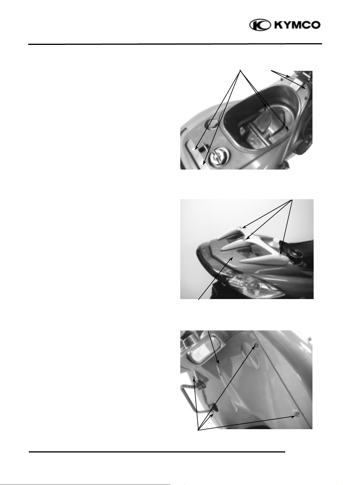
REAR CARRIER & HAND RAIL
REMOVAL
Remove the met-in box:
First remove the two bolts and two nuts and
front two screws attaching the met-in box.
Remove the met-in box.
Remove the three hex bolts attaching the rear
carrier.
Remove the rear carrier and rear center cover.
FRAME BODY COVER REMOVAL
Remove the four screws attaching on the
bottom of the frame body cover.
Remove the bottom cover.
Hex Bolts
Rear Center Cover
screws
Bolts/Nuts
Bottom Cover
Screws
Page 4

2. EXHAUST MUFFLER/FRAME COVERS
2-3
SUPER 9 50
Remove the right and left screws and bolt on
the rear part of the frame body cover.
Disconnect the air cleaner case of the air
entrance tube.
Remove the frame body cover.
FRONT UPPER COVER REMOVAL
Remove the two screws on the back of the
front upper cover.
Remove the front upper cover.
The installation sequence is the reverse of
removal.
FRONT LOWER COVER REMOVAL
First remove the front upper cover.
Remove the six screws and two bolts
attaching the front lower cover.
Remove the six screws on the back of the
front lower cover.
Disconnect the headlight wire connectors.
Remove the front lower cover
The installation sequence is the reverse of
removal.
Air Entrance Tube
Screw
Frame Body Cover
Screws
Front Upper Cover
Screws
Bolts
Page 5

2. EXHAUST MUFFLER/FRAME COVERS
2-4
SUPER 9 50
LEG SHIELD REMOVAL
Remove the front upper cover.
Remove the front lower cover.
Disconnect the leg shield and ignition switch
cover.
Remove the two bolts attaching the leg shield.
Remove the leg shield.
The installation sequence is the reverse of
removal.
FRONT TOOL BOX REMOVAL
Open the front tool box and remove the bolt.
Remove the front tool box .
Leg Shield
Bolts
Front Tool Box
Ignition Switch
Bolt
Page 6

2. EXHAUST MUFFLER/FRAME COVERS
2-5
SUPER 9 50
Remove the center cover by pulling them
backward.
Remove the center cover.
FLOOR BOARD REMOVAL
Remove the screw and two bolts attaching the
front right and left side covers. Remove the
two bottom cover attaching screws.
Remove the four bolts attaching the floor
board.
Remove the floor board .
The installation sequence is the reverse of
removal.
Center Cover
Bolts
Screws
Screws
Floor Board
Page 7

2. EXHAUST MUFFLER/FRAME COVERS
2-6
SUPER 9 50
BOTTOM COVER REMOVAL
Remove the four screws attaching the bottom
cover and inner bottom cover.
Remove the bottom cover.
FRONT INNER FENDER REMOVAL
Remove the front upper cover. (!2-3)
Remove the front lower cover. (!2-3)
Remove the leg shield and floor board.
Remove the bottom cover.
Remove the screws which combines front
fender and the front axle nut to pull out the
axle.
Remove the front fender and the front wheel
and the speedometer gear unit.
Separate inner fenders.
The installation sequence is the reverse of
removal.
EXHAUST MUFFLER REMOVAL
Remove the two exhaust muffler joint lock
nuts.
Remove the two exhaust muffler lock bolts to
remove the exhaust muffler.
Remove the exhaust muffler joint packing
collar.
The installation sequence is the reverse of
removal.
Torque:
Exhaust muffler joint lock nut: 11.8N-m
Exhaust muffler lock bolt: 34.3N-m
Fender
Screws
Screws
Bottom Cover
Lock Bolts
Joint Lock Nut
Nut
Inner Fender
Page 8

2. EXHAUST MUFFLER/FRAME COVERS
2-7
SUPER 9 50
HANDLEBAR COVER REMOVAL
Remove the four screws attaching the
handlebar lower cover.
Remove the handlebar lower cover.
Remove the four screws attaching the
handlebar upper cover.
Remove the handlebar upper cover.
The installation sequence is the reverse of
removal.
Screws
Screws
 Loading...