

Page 1

11. COOLING SYSTEM
11-0
SUPER 9 50
11
__________________________________________________________________________________
__________________________________________________________________________________
__________________________________________________________________________________
__________________________________________________________________________________
__________________________________________________________________________________
COOLING SYSTEM
__________________________________________________________________________________
SERVICE INFORMATION -------------------------------------------- 11- 1
TROUBLESHOOTING ------------------------------------------------- 11- 1
RADIATOR -------------------------------------------------------------- 11- 3
WATER PUMP ---------------------------------------------------------- 11- 6
THERMOSENSOR ------------------------------------------------------ 11-12
THERMOSTAT---------------------------------------------------------- 11-13
11
Page 2

11. COOLING SYSTEM
11-1
SUPER 9 50
SERVICE INFORMATION
GENERAL INSTRUCTIONS
• The water pump must be serviced after removing the engine. Other cooling system service can be
done with the engine installed in the frame.
• The engine must be cool before servicing the cooling system.
When the coolant temperature is over 100℃ , never remove the radiator cap to release the
pressure because the boiling coolant may cause danger.
• Avoid spilling coolant on painted surfaces because the coolant will corrode the painted surfaces.
Wash off any spilled coolant with fresh water as soon as possible.
• After servicing the system, check for leaks with a cooling system tester.
SPECIAL TOOL
Mechanical seal driver
TORQUE VALUES
Water pump impeller 9.8_ 13.72N-m
Water pump cover bolt 7.84_ 11.76N-m
TROUBLESHOOTING
Engine temperature too high Coolant leaks
• Faulty temperature gauge or thermosensor • Faulty pump mechanical (water) seal
• Faulty radiator cap • Deteriorated O-rings
• Faulty thermostat • Damaged or deteriorated water hoses
• Insufficient coolant
• Passages blocked in hoses or water jacket
• Clogged radiator fins
• Passages blocked in radiator
• Faulty water pump
Temperature gauge pointer does not register
the correct coolant temperature
• Faulty temperature gauge or thermosensor
• Faulty thermostat
Page 3
11. COOLING SYSTEM
11-2
SUPER 9 50
SPECIFICATIONS
Begins to open
80±2℃
Thermostat temperature
Full-open
90℃
Valve lift
3.5_ 4.5mm
Coolant capacity
Total system 1165cc
Radiator: 825cc
Reserve tank: 340cc
COOLANT GRAVITY
Temp. ℃
Coolant
concentration
05101520253035404550
5%
1.009
1.009
1.008
1.008
1.007
1.006
1.005
1.003
1.001
0.009
0.997
10%
1.018
1.107
1.017
1.016
1.015
1.014
0.013
1.011
1.009
1.007
1.005
15%
1.028
1.027
1.026
1.025
1.024
1.022
1.020
1.018
1.016
1.014
1.012
20%
1.036
1.035
1.034
1.033
1.031
1.029
1.027
1.025
1.023
1.021
1.019
25%
1.045
1.044
1.043
1.042
1.040
1.038
1.036
1.034
1.031
1.028
1.025
30%
1.053
1.051
1.051
1.049
1.047
1.045
1.043
1.041
1.038
1.035
1.032
35%
1.063
1.062
1.060
1.058
1.056
1.054
1.052
1.049
1.046
1.043
1.040
40%
1.072
1.070
1.068
1.066
1.064
1.062
1.059
1.056
1.053
1.050
1.047
45%
1.080
1.078
1.076
1.074
1.072
1.069
1.056
1.063
1.062
1.057
1.054
50%
1.086
1.084
1.082
1.080
1.077
1.074
1.071
1.068
1.065
1.062
1.059
55%
1.095
1.093
1.091
1.088
1.085
1.082
1.079
1.076
1.073
1.070
1.067
60%
1.100
1.098
1.095
1.092
1.089
1.086
1.083
1.080
1.077
1.074
1.071
COOLANT MIXTURE (WITH ANTI-RUST AND ANTI-FREEZING EFFECTS)
Freezing Point
Mixing Rate
KYMCO SIGMA Coolant Concentrate
Distilled Water
-9℃
20%
-15℃
30%
360cc
825cc
-25℃
40%
-37℃
50%
-44.5℃
55%
Cautions for Using Coolant:
• Use coolant of specified mixing rate. (The
mixing rate of 360cc KYMCO SIGMA
coolant concentrate + 825cc distilled
water is 30%.)
• Do not mix coolant concentrate of
different brands.
• Do not drink the coolant which is
poisonous.
• The freezing point of coolant mixture shall
be 5℃ lower than the freezing point of
the riding area.
Page 4
11. COOLING SYSTEM
11-3
SUPER 9 50
RADIATOR
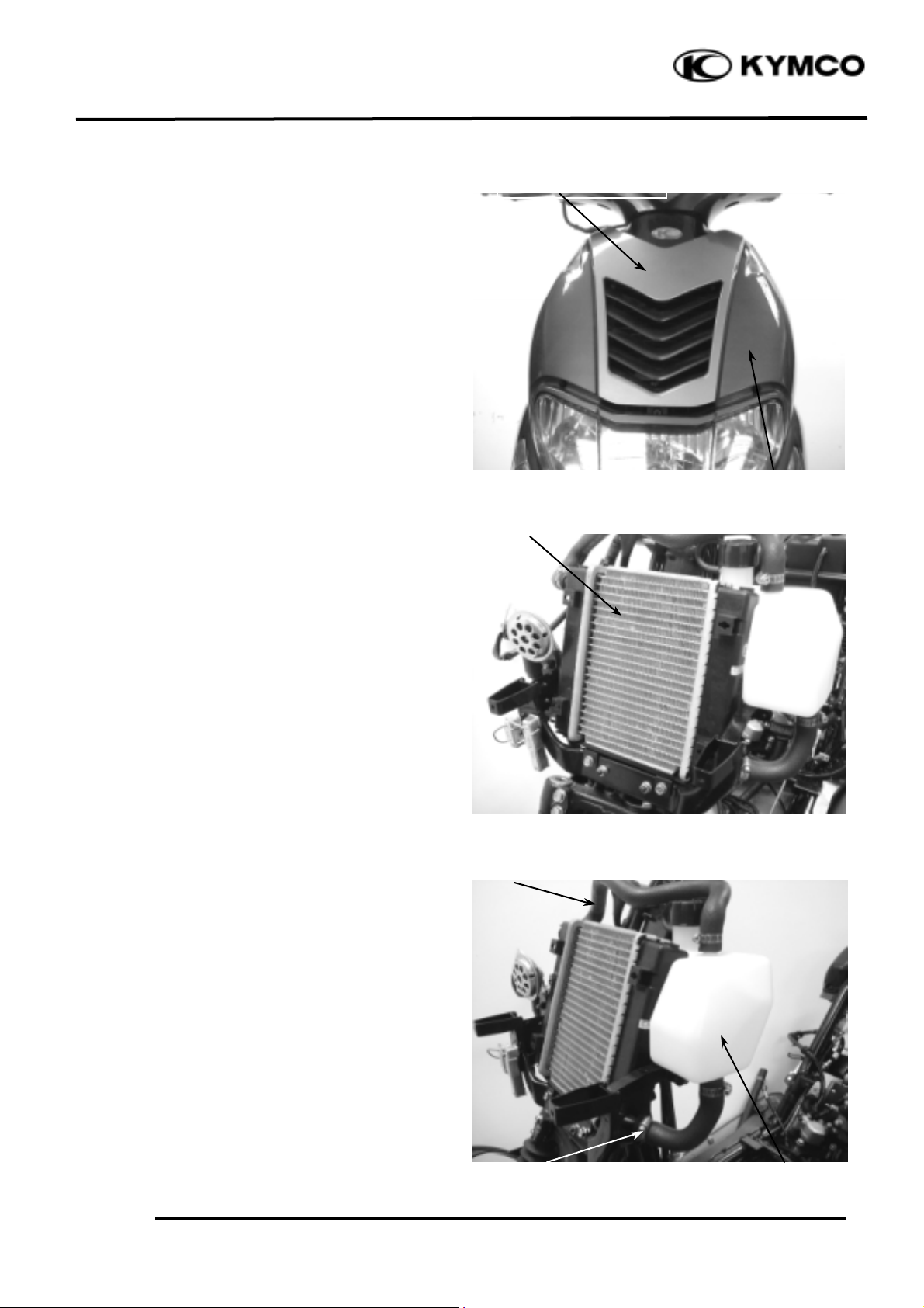
RADIATOR INSPECTION
Remove the front upper cover. (!2-3)
Remove the front lower cover. (!2-3)
Inspect the radiator soldered joints and
seams for leaks.
Blow dirt out from between core fins with
compressed air. If insects, etc., are clogging
the radiator, wash them off.
Carefully straighten any bent fins.
RADIATOR REMOVAL
Drain the coolant. (!3-10)
Loosen the hose band and disconnect the
upper and lower hose from connect the
radiator and reserve tank.
Upper Hose
Reserve Tank
Front Upper Cover
Front Lower Cover
Radiator
Lower Hose
Page 5
11. COOLING SYSTEM
11-4
SUPER 9 50
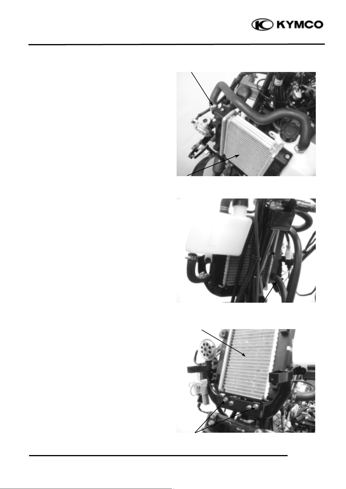
Loosen the hose band and disconnect the
upper hose from the radiator.
Loosen the hose band and disconnect the
lower hose from the radiator.
Remove the two bolts and the radiator.
Radiator
Upper Hose
Lower Hose
Radiator
Bolts
Page 6

11. COOLING SYSTEM
11-5
SUPER 9 50
RADIATOR BRACKET REMOVAL/
INSTALLATION
Remove the two nuts to remove the radiator
bracket.
The installation sequence is the reverse of
removal.
RADIATOR INSTALLATION
Install the radiator on the radiator bracket
with the two bolts.
Connect the upper and lower hoses and
secure them with hose bands.
Nuts
Radiator
Radiator Bracket
Lower Hoses
Bolts
Upper Hoses
Page 7

11. COOLING SYSTEM
11-6
SUPER 9 50
Reinstall the upper and lower hoses, make
sure the bands are secured.
Fill the reserve tank with coolant. (!3-10)
Check for coolant leaks.
Install the front upper and lower cover.
WATER PUMP
MECHANICAL SEAL (WATER SEAL)
INSPECTION
Inspect the
telltale hole for signs of
mechanical seal coolant leakage.
If the mechanical seal is leaking, remove the
right crankcase cover and replace the
mechanical seal.
.
Air Duct
Right Crankcase Cover
Upper Hose
Telltale Hole
Water Pump
Lower Hose
Reserve Tank
Reserve Tank
Page 8

11. COOLING SYSTEM
11-7
SUPER 9 50
WATER PUMP/IMPELLER REMOVAL
Remove the engine from the frame. (!5-2)
Remove the three bolts and the water pump
cover, gasket and two dowel pins.
Remove the water pump impeller.
Impeller
Water Pump Cover
Bolts
The impeller has left hand threads.
*
Page 9

11. COOLING SYSTEM
11-8
SUPER 9 50
Bolts
Water Pump Assembly
Water Hose
Bolts
Water Pump Assembly
Inspect the mechanical (water) seal and seal
washer for wear or damage.
WATER PUMP SHAFT REMOVAL
Disconnect the water hose from the right
crankcase cover.
Remove the two timing cap bolts and the
timing cap.
Remove the three bolts attaching the water
pump assembly.
Remove the water pump assembly and
dowel pins.
Remove the water pump shaft from the
water pump assembly.
Mechanical Seal
Water Pump Shaft
Impeller
Seal Washer (Porcelain)
The mechanical seal and seal washer
must be replace as a set.
*
Page 10

11. COOLING SYSTEM
11-9
SUPER 9 50
Water Pump Assembly
WATER PUMP BEARING/
MECHANICAL SEAL REMOVAL
Remove the water pump shaft inside
bearing.
Drive the mechanical seal out of the water
pump assembly from the outer.
Remove the water pump shaft outer
bearing.
Water Pump Assembly
Mechanical Seal (Water Seal)
Outer Bearing
Inside Bearing
Page 11

11. COOLING SYSTEM
11-10
SUPER 9 50
WATER PUMP BEARING/
MECHANICAL SEAL INS TALLATION
Drive a new water pump shaft
outer bearing
into the water pump assembly from the
inside.
Drive a new water pump shaft
inside
bearing into the water pump assembly from
the inside.
Drive in a new mechanical seal using a
mechanical seal driver.
Install the water pump shaft into the water
pump assembly.
Water Pump Assembly
Water Pump Shaft
Inside Bearing
Mechanical Seal
Apply sealant to the right crankcase
cover fitting surface of a new mechanical
seal and then drive in the mechanical seal.
*
Outer Bearing
Page 12

11. COOLING SYSTEM
11-11
SUPER 9 50
Install the dowel pins and then install the
water pump assembly to the right
crankcase.
Tighten the three bolts to secure the water
pump assembly.
Install the two timing cap bolts and the
timing cap.
WATER PUMP/IMPELLER
INSTALLATION
When the mechanical seal is replaced, a new
seal washer must be installed to the
impeller.
Install the impeller onto the water pump
shaft.
Torque: 9.8_ 13.72N-m
Install the two dowel pins and a new
gasket.
Install the water pump cover and tighten
the three bolts.
Torque: 7.84_ 11.76N-m
Water Pump Assembly
Water Pump Cover
Bolts
Mechanical Seal
Dowel Pins
Seal Washer (Porcelain)
The impeller has left hand threads.
*
When installing the water pump
assembly, aligning the tab on the water
pump shaft with the groove on the A.C.
generator nut.
*
Impeller
Bolts
Page 13

11. COOLING SYSTEM
11-12
SUPER 9 50
Thermosenso
Thermomete
THERMOSENSOR
THERMOSENSOR REMOVAL
Remove the seat, met-in box and frame
body cover.
Drain the coolant.
Disconnect the thermosensor wire.
Remove the thermosensor.
THERMOSENSOR INSPECTION
Suspend the thermosensor in a pan of water
over a burner and measure the resistance
through the sensor as the water heats up.
Temperature(
℃ )
5080100
120
Resistance(W)
1545227
16
THERMOSENSOR INSTALLATION
Apply 3-BOND No. 1212 sealant or
equivalent to the cylinder head threads and
install it into the thermostat housing.
Connect the thermosensor wire.
Fill the reserve tank with coolant. (!3-10)
Install the frame body cover, met-in box and
seat. (!2-3)
Thermosensor
Thermosensor Wire
Thermosensor
Be sure to bleed air from the cooling
system.
*
Page 14

11. COOLING SYSTEM
11-13
SUPER 9 50
THERMOSTAT
THERMOSTAT REMOVAL
Remove the seat, met-in box and frame
body cover.
Drain the coolant.
Disconnect the water hose from the
thermostat housing.
Remove the two screws and separate the
thermostat housing cover .
Remove the thermostat from the thermostat
housing.
THERMOSTAT INSPECTION
Suspend the thermostat in a pan of water
over a burner and gradually raise the water
temperature to check its operation.
Technical Data
Begins to open
80±2℃
Full-open
90℃
Valve lift
3.5_ 4.5mm
Thermostat Housing
Water Hose
Thermostat
Screws
Thermostat
Thermometer
• Do not let the thermostat touch the pan
as it will give a false reading.
• Replace the thermostat if the valve
stays open at room temperature.
•Test the thermostat after it is opened
for about 5 minutes and holds the
temperature at 70℃ .
*
Page 15

11. COOLING SYSTEM
11-14
SUPER 9 50
THERMOSTAT INSTALLATION
The installation sequence is the reverse of
removal.
Fill the cooling system with the specified
coolant. (!3-10)
Thermostat Housing
 Loading...