

Page 1

12. CARBURETOR
12-0
SUPER 9 50
12
__________________________________________________________________________________
__________________________________________________________________________________
__________________________________________________________________________________
__________________________________________________________________________________
__________________________________________________________________________________
CARBURETOR
__________________________________________________________________________________
SERVICE INFORMATION........................................................ 12- 1
TROUBLESHOOTING.............................................................. 12- 1
THROTTLE VALVE DISASSEMBLY ....................................... 12- 2
THROTTLE VALVE INSTALLATION...................................... 12- 3
CARBURETOR REMOVAL....................................................... 12- 4
AUTO BYSTARTER................................................................. 12- 5
FLOAT CHAMBER................................................................... 12- 7
FLOAT LEVEL INSPECTION .................................................. 12- 9
CARBURETOR INSTALLATION.............................................. 12-10
AIR SCREW ADJUSTMENT ..................................................... 12-10
REED VALVE.......................................................................... 12-11
12
Page 2
12. CARBURETOR
12-1
SUPER 9 50
SERVICE INFORMATION
GENERAL INSTRUCTIONS
• When working with gasoline, keep away from sparks and flames..
• Note the locations of O-rings when disassembling and replace them with new ones during
assembly.
• All cables, fuel lines and wires must be routed and secured at correct locations.
• Bleed air from the oil lines whenever they are disconnected.
SPECIFICATIONS
SH10DA
SF10DA
Venturi dia.
14mm
Identification number
PB088
PB088
Float level
8.6mm
Main jet(Unlimited/limited speed)
#92/#78
Slow jet
#35
Air screw opening
1_± _
Idle speed
2000±100rpm
1900±100rpm
Throttle grip free play
2_ 6mm
SPECIAL TOOL
Float level gauge
TROUBLESHOOTING
Engine does not start Lean mixture
• No fuel in tank • Clogged fuel jets • Faulty float valve
• Too much fuel getting to cylinder • Clogged fuel cap vent • Float level too low
• Clogged fuel filter • Clogged fuel filter • Clogged air cleaner
• Clogged air cleaner • Bent, kinked or restricted fuel line
Engine idles roughly, stalls or runs poorly Rich mixture
• Incorrect idle speed • Clogged air cleaner • Faulty float valve
• Ignition malfunction • Intake air leaks • Float level too high
• Compression too low • Fuel contaminated • Clogged air jets
• Incorrectly adjusted air screw • Faulty reed valve
• Incorrect float level • Clogged fuel jets
A
A
Page 3
12. CARBURETOR
12-2
SUPER 9 50
THROTTLE VALVE DISASSEMBLY
Remove the rear carrier. (!2-3)
Remove the met-in box. (!2-4)
Loosen the carburetor cap and remove the
throttle valve.
Disconnect the throttle cable from the
throttle valve.
Remove the throttle valve spring, carburetor
cap and rubber seal.
Carburetor Cap
Throttle Valve
Rubber Seal
Carburetor Cap
Spring
Page 4
12. CARBURETOR
12-3
SUPER 9 50
Remove the jet needle by removing the
needle clip.
Check the jet needle and throttle valve for
wear or damage.
THROTTLE VALVE INSTALLATION
Install the jet needle on the throttle valve
and secure with the needle clip.
Install the rubber seal on the throttle cable
and then install the carburetor cap and
throttle valve spring.
Connect the throttle cable to the throttle
valve.
Carburetor Cap
Throttle Valve
Rubber Seal
Throttle Cable
Throttle Valve Spring
Throttle Valve
Jet Needle
Needle Clip
Spring
Page 5
12. CARBURETOR
12-4
SUPER 9 50
Install the throttle valve by aligning the
groove in the throttle valve with the throttle
stop screw.
Tighten the carburetor cap.
After installation, perform the following
adjustments and inspections.
• Throttle cable free play (!3-12)
• Idle speed adjustment (!3-11)
Install the met-in box.
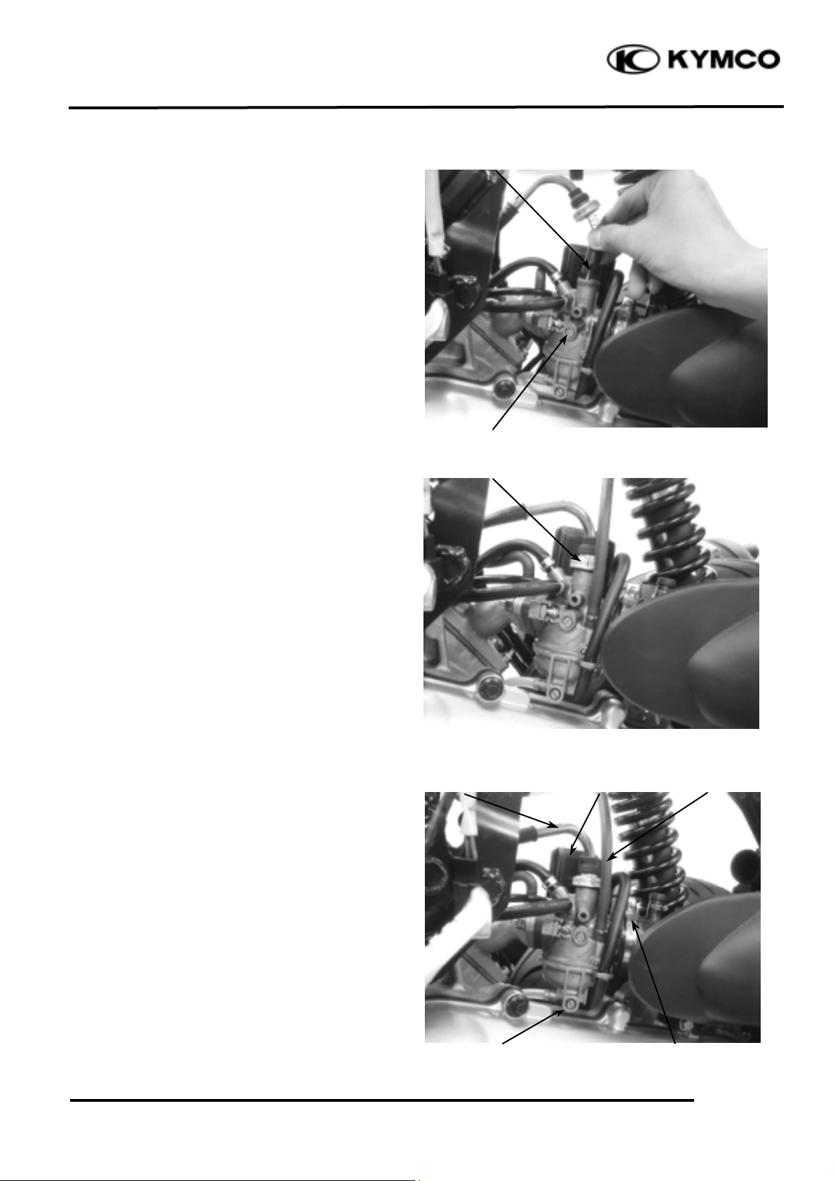
CARBURETOR REMOVAL
Remove the met-in box. (!2-3)
Remove the air cleaner by removing the air
cleaner band screw and attaching bolts.
Disconnect the fuel tube.
Loosen the drain bolt to drain fuel from the
carburetor.
Disconnect the auto bystarter wire
connector.
Carburetor Cap
Drain Bolt
Throttle Cable
Throttle Stop Screw
Groove
Fuel Tube
Band
Auto Bystarter
Page 6

12. CARBURETOR
12-5
SUPER 9 50
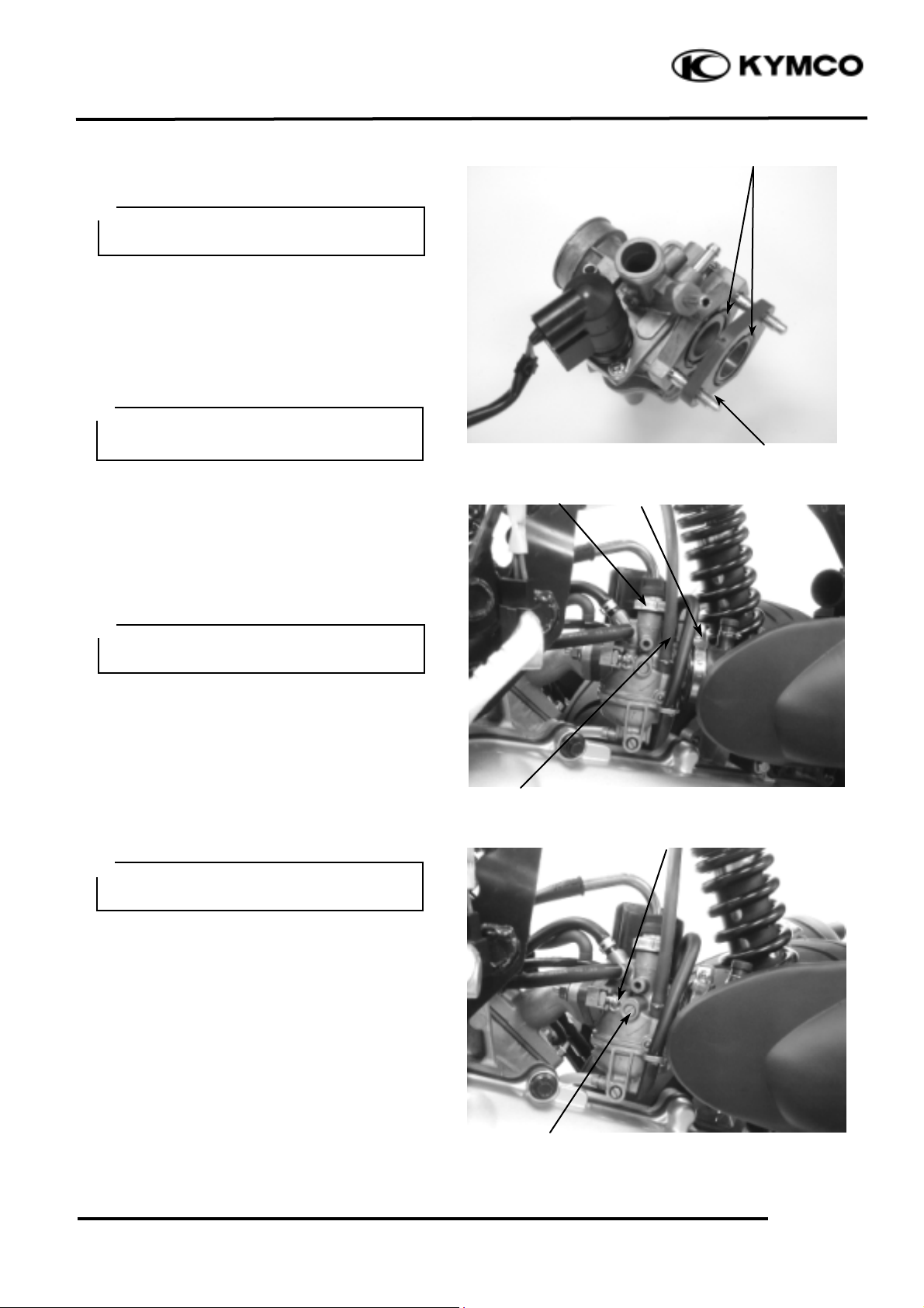
Remove the two carburetor lock nuts.
Remove the carburetor and water hose.
AUTO BYSTARTER
AUTO BYSTARTER INSPECTION
Measure the resistance between the auto
bystarter wire terminals.
Resistance: 5W (10 minutes minimum
after stopping the engine)
If the resistance exceeds 5W, replace the
auto bystarter with a new one.
After the engine stops for 30 minutes,
connect a hose to the fuel enriching circuit
and blow the hose with mouth.
If air cannot be blown into the hose
(clogged), the auto bystarter is faulty.
Replace it with a new one.
Nut
Bolt
Water Hose
Page 7

12. CARBURETOR
12-6
SUPER 9 50
Connect the auto bystarter yellow wire to
the battery positive (+) terminal and green/
black wire to the battery negative (-)
terminal and wait 5 minutes.
Connect a hose to the fuel enriching circuit
and blow the hose with mouth.
If air can be blown into the hose, the auto
bystarter is faulty and replace it with a new
one.
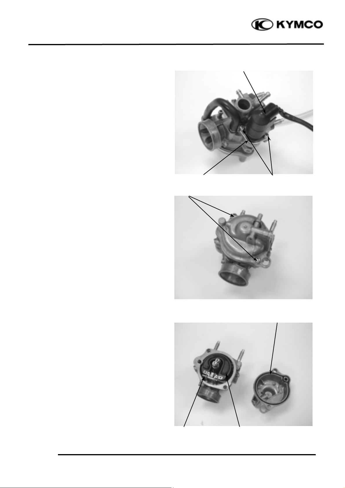
AUTO BYSTARTER REMOVAL
Remove the auto bystarter cover.
Remove the two auto bystarter set plate
screws to remove the auto bystarter.
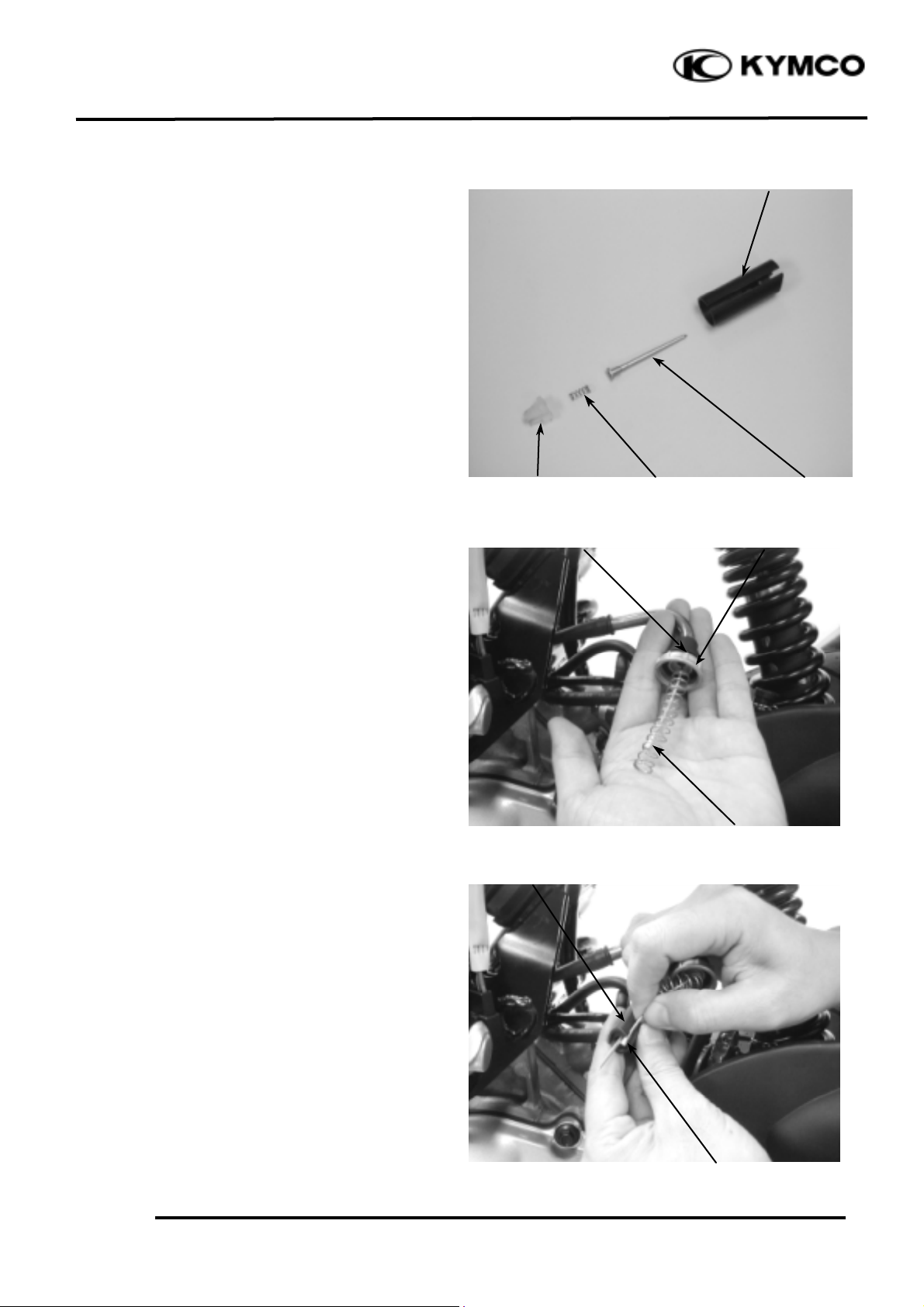
Check the auto bystarter valve and needle
for wear or damage.
Check the O-ring for wear or damage.
Auto Bystarter
Screws
O-ring
Set Plate
Bystarter Valve
Bystarter
Needle
Page 8
12. CARBURETOR
12-7
SUPER 9 50
AUTO BYSTARTER INSTALLATION
Install the auto bystarter into the carburetor
body until it bottoms..
Install the set plate and then tighten the two
screws.
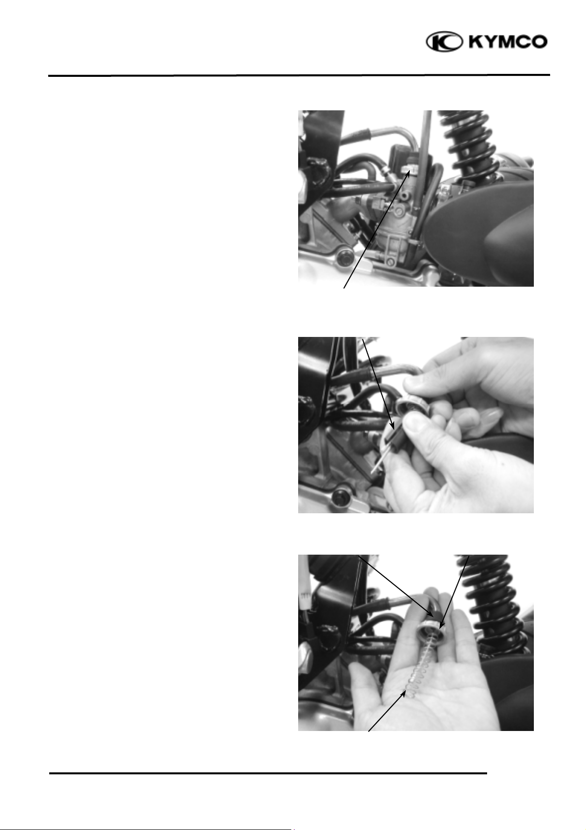
FLOAT CHAMBER
Remove the two float chamber screws and
the float chamber.
Remove the screw and O-ring.
Remove the float pin, float and float valve.
Auto Bystarter
Float
Bolt
O-ring
Float Pin
Screws
Bolt
Screws
Set Plate
Page 9

12. CARBURETOR
12-8
SUPER 9 50
FLOAT/FLOAT VALVE INSPECTION
Inspect the float for damage or fuel inside
the float.
Check the float valve seat for wear or
damage.
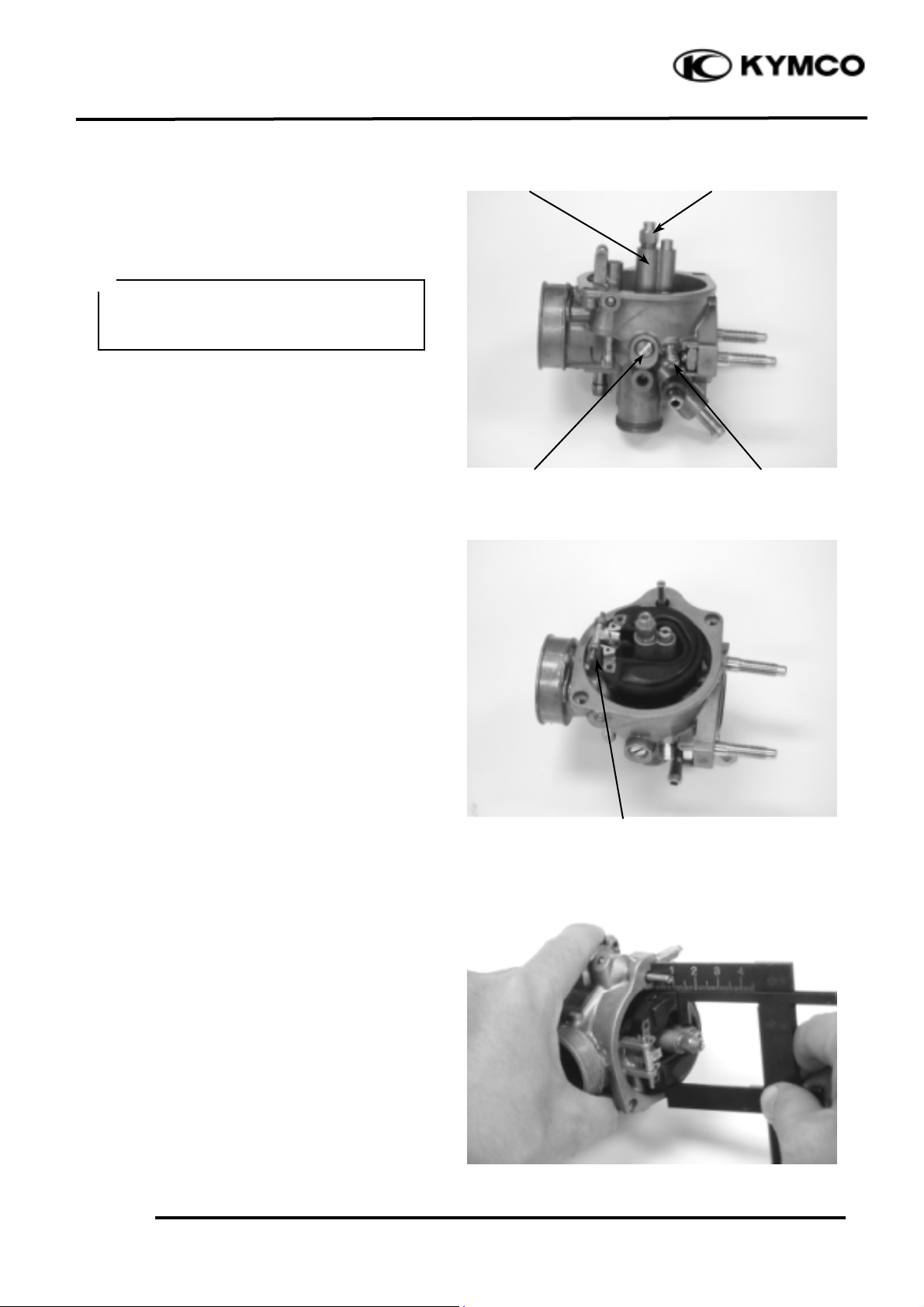
JETS/SCREWS REMOVAL
Before removing the throttle stop screw or
air screw, record the number of rotations
until it seats lightly. Then, remove them.
Remove the main jet and needle jet holder.
CARBURETOR PASSAGES CLEANING
Blow compressed air through all passages
of the carburetor body with an air gun.
Float Valve
Float Seat
Main Jet
Throttle Stop Screw
Air Screw
Do not force the air screw against its
seat to prevent damage.
*
Page 10
12. CARBURETOR
12-9
SUPER 9 50
FLOAT CHAMBER ASSEMBLY
Install the main jet and needle jet holder.
Install the air screw and throttle stop screw
according to the rotations recorded.
Install the float valve, float and float pin.
Tighten the float screw securely.
FLOAT LEVEL INSPECTION
Slightly tilt the carburetor and measure the
float level with the float valve just
connecting the float arm.
Float Level: 8.6 mm
Replace the float if the level is out of the
specified level range.
Install the O-ring.
Check the operation of the float and install
the float chamber.
Tighten the screws.
If the air screw must be replaced, be sure
to perform the air screw adjustment
again.
*
Air Screw
Throttle Stop Screw
Needle Jet holder
Float Pin
Main Jet
Page 11
12. CARBURETOR
12-10
SUPER 9 50
CARBURETOR INSTALLATION
Check the carburetor insulator and O-ring
for wear or damage.
Install the carburetor and insulator onto the
intake manifold and tighten the two lock
nuts.
Connect the fuel tube and auto bystarter
wire connector.
Install the carburetor cap. (!12-4)
Install the air cleaner onto the carburetor
and tighten the band screw.
Install the met-in box. (
!2-3
)
AIR SCREW ADJUSTMENT
Remove the met-in box. (
!2-3
)
Turn the air screw clockwise until it seats
lightly and back it to the specification given.
Air Screw Opening:
SH10DA: 1_ ± _ turns
Start the engine and turn the air screw in or
out slowly to obtain the highest engine
speed.
Turn the throttle stop screw to obtain the
specified idle speed.
Idle Speed:
SH10DA: 2000±100rpm
Slightly increase the engine speed and make
sure that the engine does not miss or run
erratic.
If the adjustment of the air screw within the
range of ±_ turn makes no difference to the
engine performance, check other related
items.
When installation, do not allow foreign
particles to enter the carburetor.
*
Route the auto bystarter wire correctly
and properly.
*
Warm up the engine before air screw
adjustment.
*
Do not force the air screw against its
seat to prevent damage.
*
Air Screw
Throttle Stop Screw
O-rings
Insulator
Carburetor Cap
Fuel Tube
Band
Page 12
12. CARBURETOR
12-11
SUPER 9 50
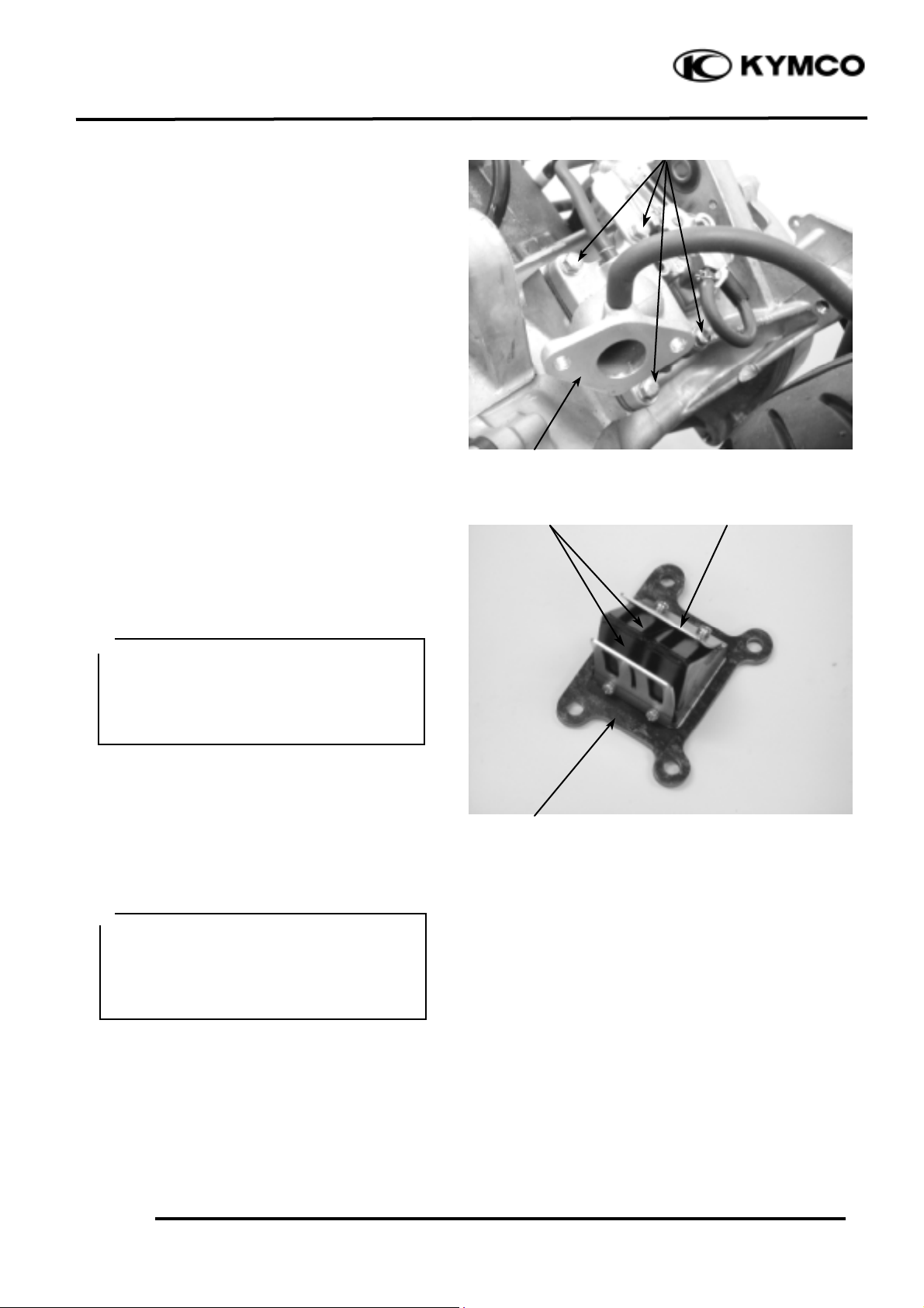
REED VALVE
REMOVAL
Remove the rear carrier.
Remove the frame body cover.
Remove the four intake manifold bolts and
gasket.
Remove the reed valve and gasket.
INSPECTION
Check the reed valve for damaged or weak
reeds.
Check the reed valve seat for cracks, damage
or clearance between the seat and reed.
Replace the valve if necessary.
INSTALLATION
Install the reed valve in the reverse order of
removal.
• Install a new gasket with the gasket
indentation aligned with the reed
valve.
• After installation, check for intake air
leaks.
*
Bolts
Do not disassemble or bend the reed
stopper. To do so can cause loss of
engine power and engine damage. If any
of the stopper, reed or valve seat is
faulty, replace them as a unit.
*
Reeds
Intake Manifold
Reed Valve Seat
Reed Stopper
 Loading...