

Page 1

12. FRAME COVERS
12-0
12
__________________________________________________________________________________
__________________________________________________________________________________
__________________________________________________________________________________
__________________________________________________________________________________
__________________________________________________________________________________
FRAME COVERS
__________________________________________________________________________________
SERVICE INFORMATION........................................................ 12-2
FRAME COVERS REMOVAL/INSTALLATION ........................ 12-3
12
Page 2
12. FRAME COVERS
12-1
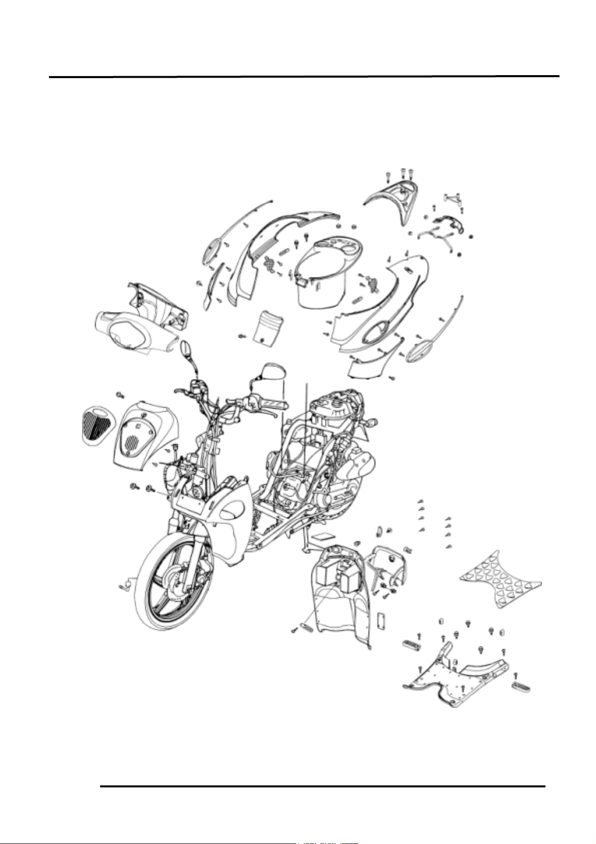
ASSEMBLY DRAWING
Page 3

12. FRAME COVERS
12-2
SERVICE INFORMATION
• When removing frame covers, use care not to pull them by force because the cover joint claws
may be damaged.
Items Related for Removal
• Handlebar front cover Headlight wire
• Front cover
• Handlebar rear cover Speedometer cable and instrument light
wire connectors, etc.
• Frame body cover Met-in box, rear carrier,rear fender.
• Floor board frame body cover.
• Front tool box Front cover, battery, floor board .
Page 4

12. FRAME COVERS
12-3
FRAME COVERS REMOVAL
FRONT COVER REMOVAL
Remove the screw the front cover.
Remove the two screws on the back of the
front cover.
Push the two inside claws of the downside
front cover to float the front cover.
Remove the front cover downward.
The installation sequence is the reverse of
removal.
HANDLEBAR FRONT/REAR COVER
REMOVAL
First remove the one screws attaching the
handlebar front cover.
Remove the handlebar front cover.
Disconnect the headlight wire connector.
Remove the handlebar rear cover:
Remove the four screws and bolt attaching the
handlebar rear cover.
Disconnect the speedometer cable and
instrument light wire connectors.
Remove the handlebar rear cover.
The installation sequence is the reverse of
removal.
Front Cover
Screws
Screws
During removal, be careful not to pull
the joint claws forcibly.
*
Handlebar Rear Cover
Front Tool Box
Screw
Screws
Screws
Page 5

12. FRAME COVERS
12-4
FLOOR BOARD REMOVAL
Remove the rear carrier. (!12-5)
Remove the frame body cover. (!12-6)
Remove the front cover. (!12-3)
Remove the four bolts attaching and six screws
the floor board to remove the floor board.
The installation sequence is the reverse of
removal.
FRONT TOOL BOX REMOVAL
Remove the rear carrier. (!12-5)
Remove the frame body cover. (!12-6)
Remove the floor board. (!12-4)
Open the front tool box and remove the
battery.
Remove the switch covers.
Remove the nut attaching and six screws the
front tool box.
Remove the front tool box
The installation sequence is the reverse of
removal.
BOTTOM COVER REMOVAL
Remove the flood board. (!12-4)
Remove the three screws each side of
the bottom cover.
Remove the bolt attaching the side stand.
Remove the bottom cover.
The installation sequence is the reverse of
removal.
Screws
Battery
Floor Board
Nut
Bolts
Front Tool Box
Bottom Cover
When removing the battery, first
disconnect the battery negative (-) cable
and then the positive (+) cable.
When taking the front tool box, pull
them up and backward from downside
not to damage the claws.
*
screws
Bolt
Page 6

12. FRAME COVERS
12-5
MET-IN BOX REMOVAL:
Open the seat.
Remove the two bolts, two nuts attaching the
met-in box.
Remove the oil tank cap, rubber packing and
fuel tank cap.
Remove the met-in box.
The installation sequence is the reverse of
removal .
REAR CARRIER REMOVAL
Remove the three bolts attaching the rear
carrier.
Remove the rear carrier.
The installation sequence is the reverse of
removal.
REAR FENDER REMOVAL
Remove the two screws the rear fender.
Remove the rear fender.
The installation sequence is the reverse of
removal.
Rear Carrier
Bolts
Met-in Box
Bolts
fuel tank cap
Nuts
Rubber Packing
Oil Tank Cap
Screws
Rear Fender
Page 7

12. FRAME COVERS
12-6
FRAME BODY COVER REMOVAL
Remove the rear carrier. (!12-5)
Remove the rear fender. (!12-5)
Remove the met-in box. (!12-4)
Remove the rear brake cable.
Remove the bolt attaching the front center cover
of the frame body cover.
Remove the frame body cover.
The installation sequence is the reverse of
removal.
FRONT FENDER REMOVAL
Remove the floor board. (!12-4)
Remove the front tool box.(!12-4)
Remove the handlebar. (!13-3)
Remove the front fork. (!13-19)
Remove two bolts attaching each side of the
front fender.
Remove the front fender.
The installation sequence is the reverse of
removal.
FRONT LOWER COVERS REMOVAL
Remove the rear brake cable.
Remove the frame body cover. (!12-5)
Remove the front tool box.(!12-4)
Remove the handlebar. (!13-3)
Remove the front fork. (!13-19)
First remove the front cover. (!12-3)
Remove the right and left bottom cover
removing the two screws for each rail.
Remove the two bolts attaching each of the
right and left front lower covers.
Remove the front lower covers.
The installation sequence is the reverse of
removal.
Bolts
Front Fender
Bolt
Bolts
Front Lower Cover
frame body
 Loading...