

Page 1
14. REAR WHEEL/REAR BRAKE/REAR
SHOCK ABSORBER
14-0
14
__________________________________________________________________________________
__________________________________________________________________________________
__________________________________________________________________________________
__________________________________________________________________________________
__________________________________________________________________________________
REAR WHEEL/REAR BRAKE/REAR
SHOCK ABSORBER
__________________________________________________________________________________
SERVICE INFORMATION........................................................ 14-2
TROUBLESHOOTING.............................................................. 14-2
REAR WHEEL ......................................................................... 14-3
REAR BRAKE .......................................................................... 14-4
REAR SHOCK ABSORBER....................................................... 14-7
14
Page 2
14. REAR WHEEL/REAR BRAKE/REAR
SHOCK ABSORBER
14-1
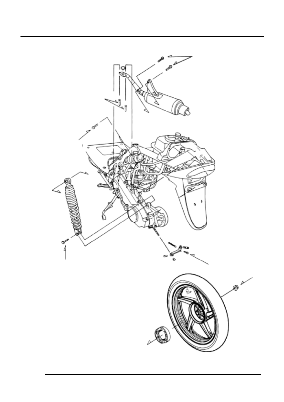
2.7kg-m
0.6kg-m
11.0kg-m
1.2kg-m
4.0kg-m
2.5kg-m
Page 3
14. REAR WHEEL/REAR BRAKE/REAR
SHOCK ABSORBER
14-2
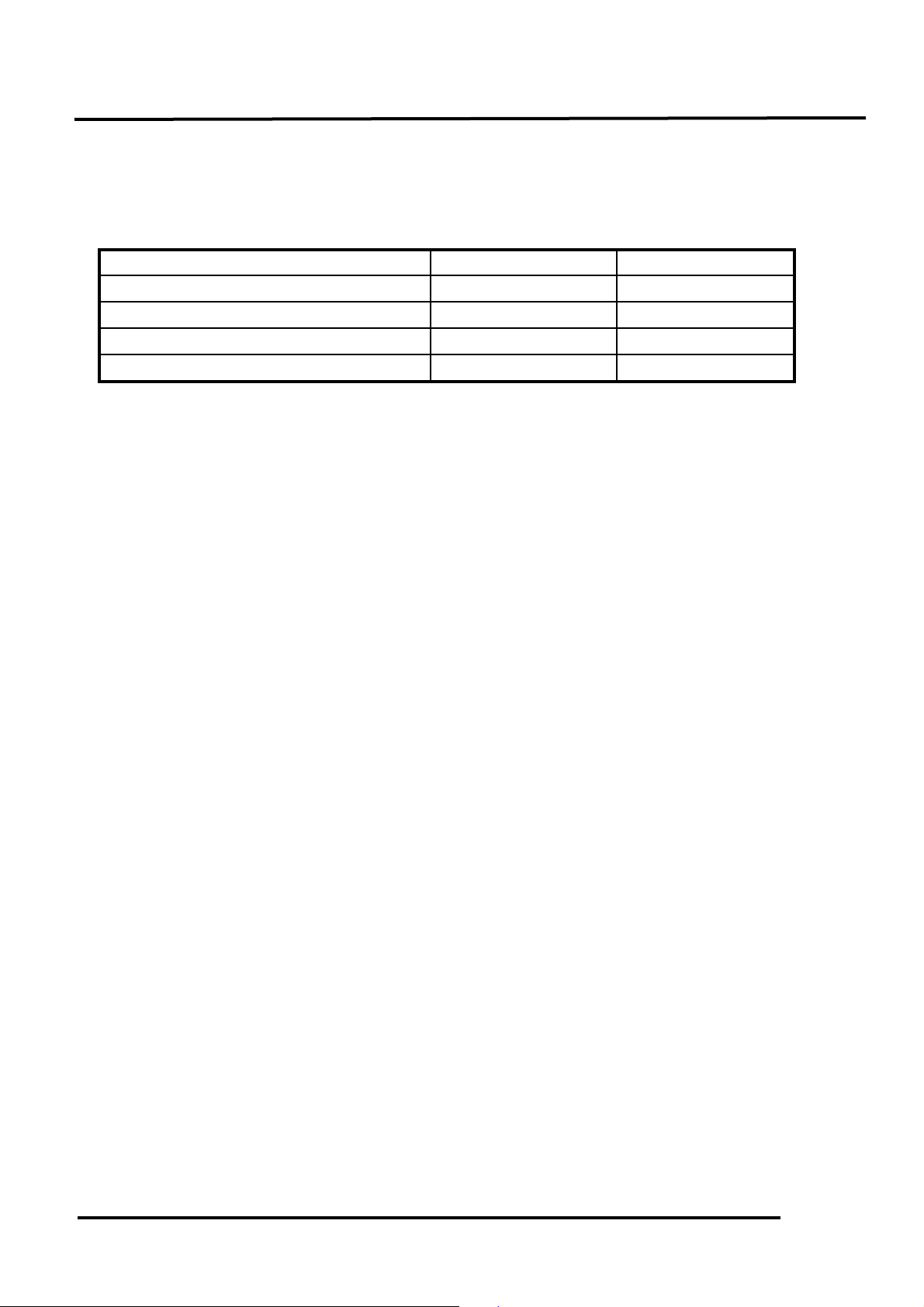
SERVICE INFORMATION
SPECIFICATIONS
Item
Standard (mm)
Service Limit (mm)
Rear wheel rim runout
2.0
Rear brake drum I.D.
110
111
Rear brake lining thickness
4.0
2.0
Rear shock absorber spring free length
235.7
218.7
TORQUE VALUES
Rear axle nut 11.0_ 13.0kg-m
Rear shock absorber upper mount bolt 3.5_ 4.5kg-m
Rear shock absorber lower mount bolt 2.4_ 3.0kg-m
Rear shock absorber lower joint nut 3.5_ 4.5kg-m (apply locking agent)
SPECIAL TOOL
Rear shock absorber remover
Rear shock absorber compressor
TROUBLESHOOTING
Rear wheel wobbling
• Bent rim
• Faulty tire
• Axle not tightened properly
Soft rear shock absorber
• Weak shock absorber spring
Poor brake performance
• Brake not adjusted properly
• Contaminated brake linings
• Worn brake linings
• Worn brake shoes at cam contacting area
• Worn brake cam
• Improper engagement between brake arm
and wear indicator plate
Page 4

14. REAR WHEEL/REAR BRAKE/REAR
SHOCK ABSORBER
14-3
REAR WHEEL
REMOVAL
Remove the two exhaust muffler joint lock
nuts.
Remove the two exhaust muffler lock bolts.
Remove the exhaust muffler.
Remove the rear axle nut to remove the rear
wheel.
INSPECTION
Measure the rear wheel rim runout.
Service Limits:
Radial : 2.0mm replace if over
Axial : 2.0mm replace if over
INSTALLATION
Install the rear wheel and apply SAE30#
engine oil to the axle threads. Then, tighten
the rear axle nut.
Torque values:
Rear axle nut: 11.0_ 13.0kg-m
Rear Axle Nut
Rear Axle Nut
Page 5

14. REAR WHEEL/REAR BRAKE/REAR
SHOCK ABSORBER
14-4
REAR BRAKE
Remove the rear wheel. (!14-3)
Inspect the rear brake drum.
Measure the rear brake drum I.D.
Service Limit: 95.5mm replace if over
BRAKE LINING INSPECTION
Measure the brake lining thickness.
Service Limit: 2.0mm replace if below
REAR BRAKE DISASSEMBLY
Remove the rear brake adjusting nut and
disconnect the rear brake cable.
Remove the rear brake shoes.
Adjusting Nut
Brake Arm
Brake Shoes
Keep oil or grease off the brake linings.
*
Page 6

14. REAR WHEEL/REAR BRAKE/REAR
SHOCK ABSORBER
14-5
Remove the brake cam bolt to remove the
brake arm, wear indicator plate and felt seal.
Remove the. brake arm.
REAR BRAKE ASSEMBLY
Apply grease to the anchor pin and brake
shoe moving parts.
Apply grease to the brake cam and install it.
Apply engine oil to the felt seal and install
it to the brake cam.
Install the wear indicator plate.
Install the brake arm onto the brake cam.
Install and tighten the brake arm bolt.
Install the brake arm return spring.
Install the brake shoes.
Align the wide tooth of the wear
indicator plate with the wide groove on
the brake cam.
*
Brake Arm Bolt
Wear Indicator Plate
Brake Arm
Brake Cam
Grease
Brake Arm
Punch Mark
Wear Indicator Plate
Align the punch mark on the brake arm
with the scribed line on the brake cam.
*
Page 7

14. REAR WHEEL/REAR BRAKE/REAR
SHOCK ABSORBER
14-6
Install the brake arm pin.
Connect the brake cable and install the
adjusting nut.
Install the rear wheel. (!14-3)
Adjust the rear brake lever free play.
(!3-4)
Brake Arm
Adjusting Nut
Brake Arm Pin
Brake Cable
Page 8

14. REAR WHEEL/REAR BRAKE/REAR
SHOCK ABSORBER
14-7
REAR SHOCK ABSORBER
REMOVAL
Remove the front cover. (!12-6)
Remove the met-in box. (!12-5)
Remove the air cleaner case. (!5-2)
Remove the rear shock absorber upper and
lower mount bolts to remove the rear shock
absorber.
DISASSEMBLY
Install the rear shock absorber compressor
as the figure shown.
Compress the rear shock absorber spring.
Loosen the lower joint lock nut.
Remove the lower joint.
Remove the lock nut, rubber and damper.
Rear Shock Absorber Compressor
Lock Nut
Upper Mount Bolt
Install the rear shock absorber lower
joint into the rear shock absorber
compressor.
*
Lower Mount Bolt
Rear Shock Absorber
Rear Shock Absorber Remover
Page 9

14. REAR WHEEL/REAR BRAKE/REAR
SHOCK ABSORBER
14-8
INSPECTION
Inspect the damper rod for bending or
damage.
Inspect the damper for oil leaks.
Inspect the damper rubber for deterioration
or damage.
Measure the rear shock absorber spring free
length.
Service Limit: 232mm replace if below
ASSEMBLY
Assemble the rear shock absorber in the
reverse order of disassembly.
Tighten the lock nut.
Torque: 3.5_ 4.5kg-m
Spring
Damper Rod
Damper
Rubber
• Install the shock absorber spring with
loosely wound coils facing down.
• Apply locking agent to the lock nut
thread and then install and tighten the
lock nut.
*
Page 10

14. REAR WHEEL/REAR BRAKE/REAR
SHOCK ABSORBER
14-9
INSTALLATION
Install the rear shock absorber.
Install the rear shock absorber upper mount
bolt and then install the lower mount bolt.
Torque:
Upper Mount Bolt: 3.5_ 4.5kg-m
Lower Mount Bolt: 2.4_ 3.0kg-m
Install the frame body cover. (!12-5)
Upper Mount Bolt
Lower Mount Bolt
 Loading...