

Page 1

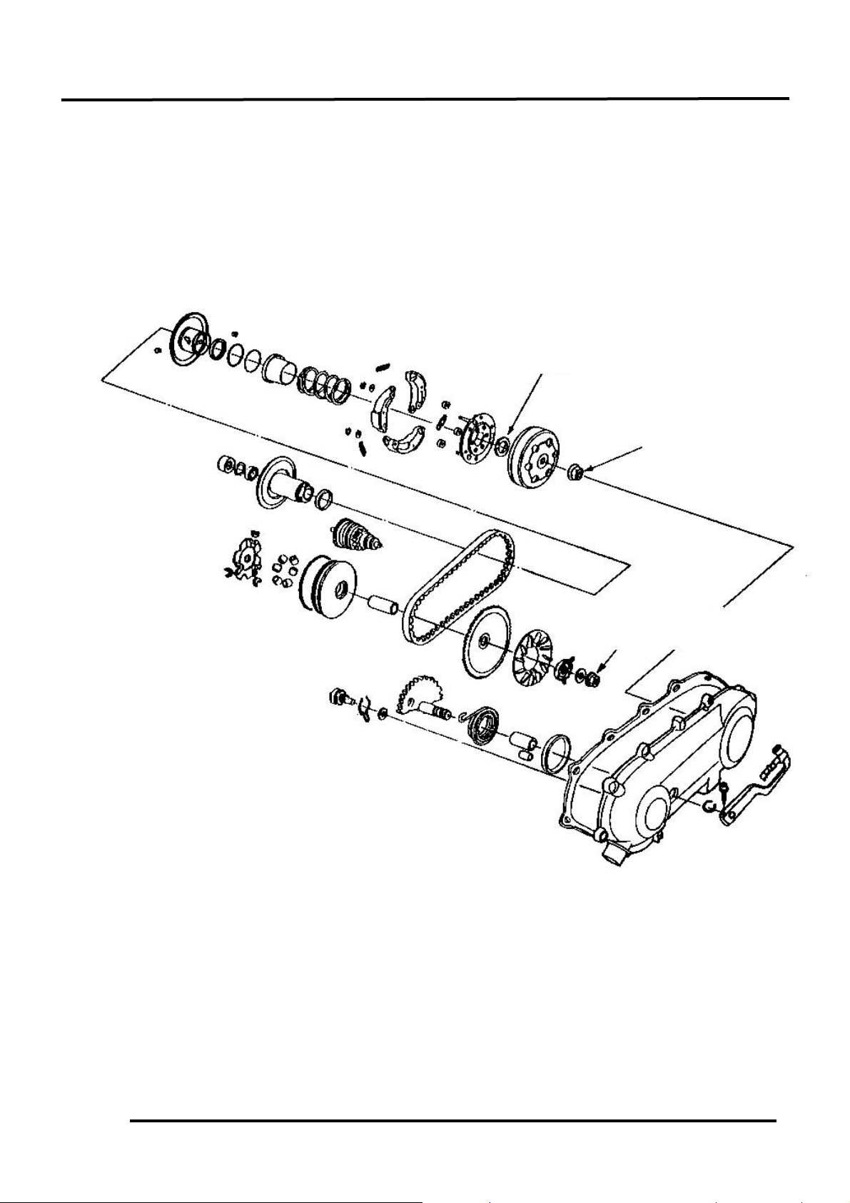
8. KICK STARTER/DRIVE PULLEY/
CLUTCH/DRIVEN PULLEY
8-0
8
__________________________________________________________________________________
__________________________________________________________________________________
__________________________________________________________________________________
__________________________________________________________________________________
__________________________________________________________________________________
KICK STARTER/DRIVE PULLEY/
CLUTCH/DRIVEN PULLEY
__________________________________________________________________________________
SERVICE INFORMATION........................................................ 8- 3
TROUBLESHOOTING.............................................................. 8- 3
KICK STARTER....................................................................... 8- 4
DRIVE BELT ........................................................................... 8- 8
DRIVE PULLEY....................................................................... 8-10
STARTER ONE-WAY CLUTCH DRIVE GEAR ......................... 8-12
CLUTCH/DRIVEN PULLEY ..................................................... 8-15
8
Page 2
8. KICK STARTER/DRIVE PULLEY/
CLUTCH/DRIVEN PULLEY
8-1
MODEL BA10AB.AC.
Torque:
3.5_ 4.5kg-m
Torque:
5.0_ 6.0kg-m
Torque:
3.5_ 4.0kg-m
Page 3
8. KICK STARTER/DRIVE PULLEY/
CLUTCH/DRIVEN PULLEY
8-2
SERVICE INFORMATION
GENERAL INSTRUCTIONS
• Avoid getting grease and oil on the drive belt and pulley faces.
SPECIFICATIONS
BA10AB.AC.50
Item
Standard (mm)
Service Limit (mm)
Drive pulley collar O.D.
20.01_ 20.025
24.24
Movable drive face I.D.
20.035_ 20.085
19.97
Weight roller O.D.
13.0
12.4
Clutch outer I.D.
107_ 107.2
107.5
Driven face spring free length
87.9
82.6
Driven face O.D.
33.965_ 33.985
33.94
Movable driven face I.D.
34.0_ 34.25
34.06
Drive belt width
18
17
TORQUE VALUES
Drive face nut 3.5_ 4.0kg-m
Clutch outer nut 3.5_ 4.5kg-m
Clutch drive plate nut 5.0_ 6.0kg-m
SPECIAL TOOLS
Lock nut wrench, 39mm Universal holder
Clutch spring compressor Lock nut socket wrench, 32mm
Bearing outer driver 37x40mm Bearing driver pilot, 17mm
One-way clutch puller Outer driver, 24x26mm
TROUBLESHOOTING
Poor performance at high speed or
Engine starts but motorcycle won‘t move lack of power
• Worn drive belt • Worn drive belt
• Broken ramp plate • Weak driven face spring
• Worn or damaged clutch lining • Worn weight roller
• Faulty driven face
Engine stalls or motorcycle creeps
• Broken clutch weight spring
Page 4
8. KICK STARTER/DRIVE PULLEY/
CLUTCH/DRIVEN PULLEY
8-3
KICK STARTER
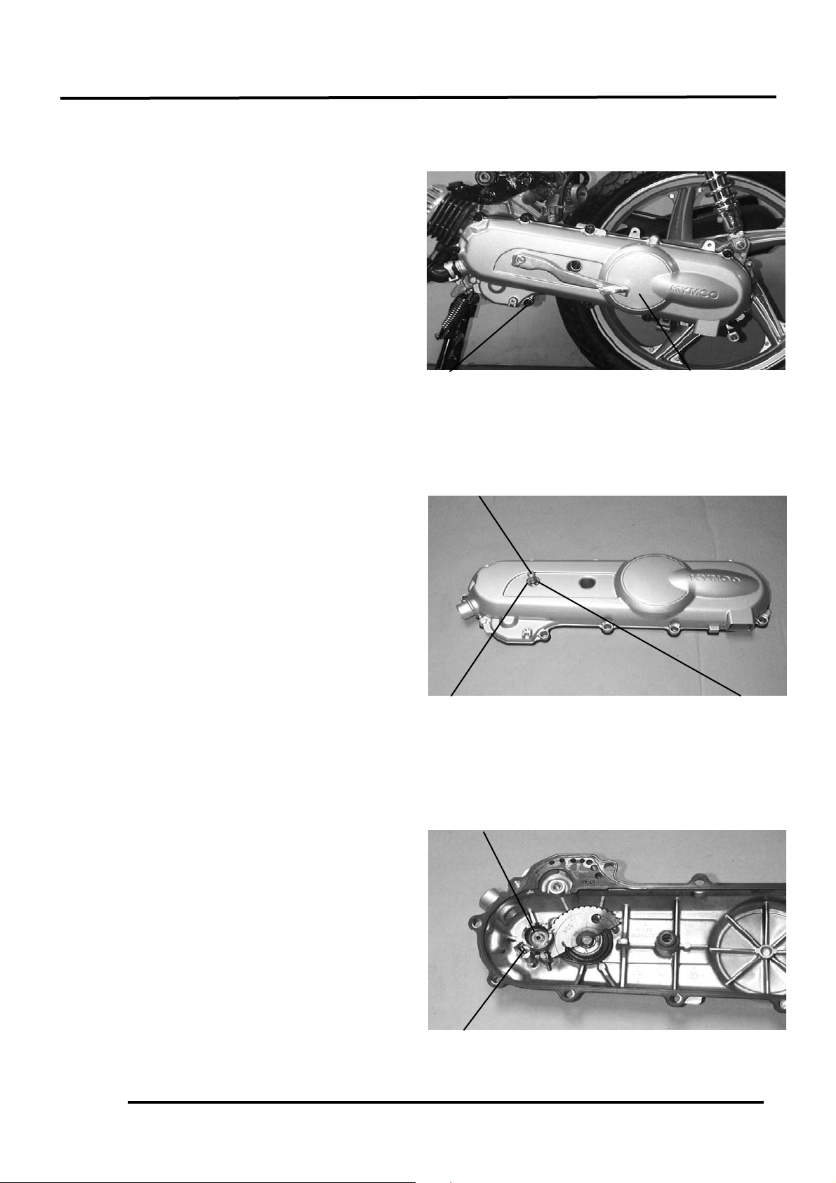
LEFT CRANKCAS E COVER REMOVAL
Remove the drive belt cooling air tube
connector circlip.
Remove the nine left crankcase cover bolts,
left crankcase cover and dowel pins.
Inspect the left crankcase cover seal rubber
for damage or deterioration.
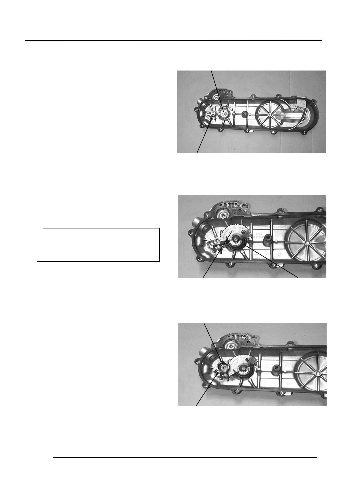
KICK STARTER SPINDLE REMOVAL
Remove the kick lever from the kick starter
spindle.
Remove the circlip and washer from the
kick starter spindle.
Slightly rotate the kick starter spindle to
remove the kick starter driven gear together
with the friction spring.
Left Crankcase Cover
Bolt
Friction Spring
Kick Starter Driven Gear
Kick Starter Spindle
Washer
Circlip
Page 5
8. KICK STARTER/DRIVE PULLEY/
CLUTCH/DRIVEN PULLEY
8-4
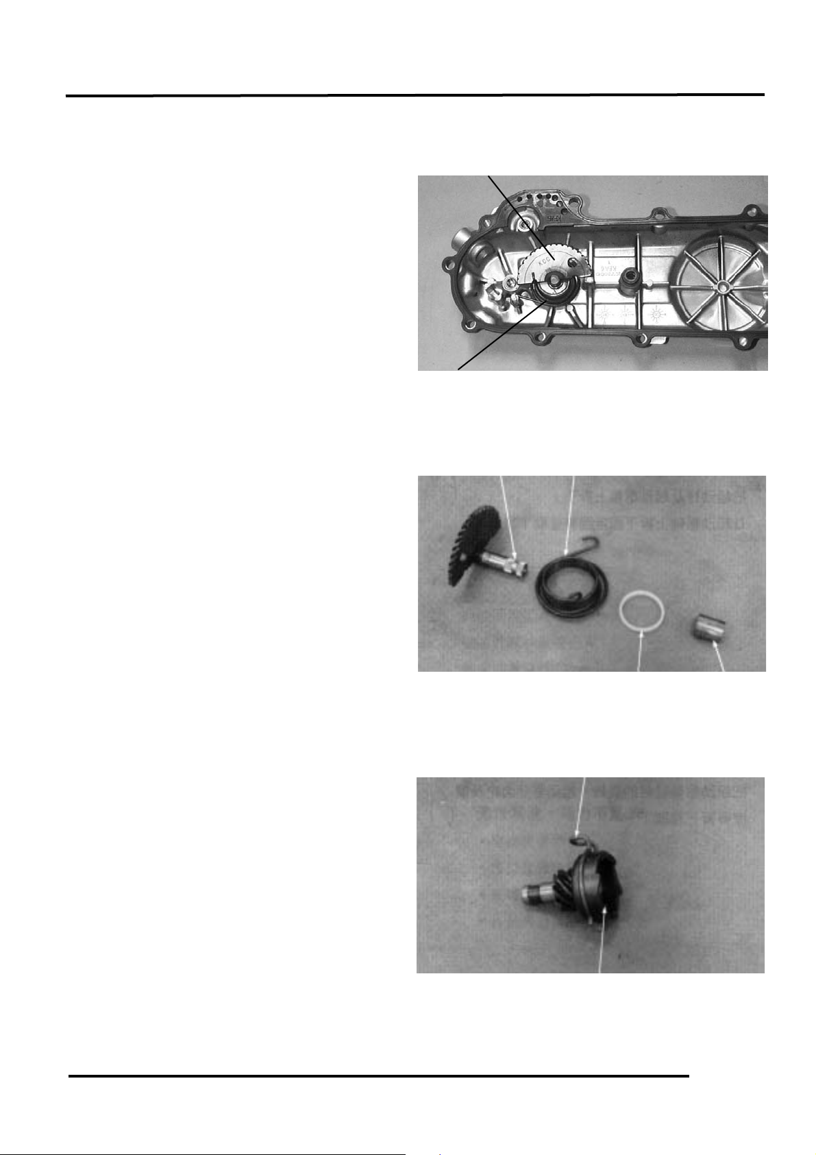
Remove the kick starter spindle and return
spring from the left crankcase cover.
Remove the kick starter spindle bushing.
KICK STARTER SPINDLE INSPECTION
Inspect the kick starter spindle and gear for
wear or damage.
Inspect the return spring for weakness or
damage.
Inspect the kick starter spindle bushing for
wear or damage.
Check the kick starter driven gear for wear
or damage.
Check the friction spring for wear or
damage.
Kick Starter Spindle
Return Spring
Spindle
Plastic Bushing
Spindle Bushing
Return Spring
Friction Spring
Kick Starter Driven Gear
Page 6
8. KICK STARTER/DRIVE PULLEY/
CLUTCH/DRIVEN PULLEY
8-5
Inspect the kick starter spindle and driven
gear forcing parts for wear or damage.
KICK STARTER INSTALLATION
Install the kick starter spindle bushing and
return spring onto the left crankcase cover.
Properly install the kick starter driven gear
and friction spring as the figure shown.
If the hooks of the return spring can not
be installed properly, use a screw driver
to press them into their locations
respectively.
*
Kick Starter Spindle Forcing Part
Kick Starter Driven Gear Forcing Part
Friction Spring
Kick Starter Spindle
Friction Spring
Kick Starter Driven Gear
Page 7

8. KICK STARTER/DRIVE PULLEY/
CLUTCH/DRIVEN PULLEY
8-6
First install the washer and then the circlip
onto the kick starter spindle.
Install the kick lever.
LEFT CRANKCASE COVER
INSTALLATION
First install the dowel pins and then the seal
rubber.
Install the left crankcase cover and tighten
the ten bolts diagonally.
Connect the drive belt cooling air tube and
install the circlip.
Left Crankcase Cover
Rear Brake Cable Clamp
Seal Rubber
Dowel Pins
Washer
Circlip
For drum brake, note the location of the
brake cable clamp and install the rear
brake cable in place with the clamp.
*
Page 8

8. KICK STARTER/DRIVE PULLEY/
CLUTCH/DRIVEN PULLEY
8-7
DRIVE BELT
Remove the left crankcase cover.
INSPECTION
Check the drive belt for cracks, separation
or abnormal or excessive wear.
Measure the drive belt width.
Service Limit:
BA10AB.AC.50: 16.5mm replace if below
REPLACEMENT
Remove the ten left crankcase cover bolts
and left crankcase cover. (!8-4)
Hold the clutch outer with the universal
holder and remove the 10mm clutch outer
nut and clutch outer.
Hold the drive pulley with the holder and
remove the 12mm drive face nut.
Remove the starting ratchet.
Remove the drive pulley face.
Use specified genuine parts for replacement.
*
Clutch Outer
Drive Face Nut
Drive Face
Universal Holder
Clutch Outer Nut
Ratchet
Page 9

8. KICK STARTER/DRIVE PULLEY/
CLUTCH/DRIVEN PULLEY
8-8
Remove the drive belt from the clutch/
driven pulley.
DRIVE BELT INSTALLATION
Turn the driven pulley clockwise and lift it
up to expand the drive belt groove and then
install a new drive belt.
Set the drive belt on the drive pulley.
Install the drive pulley face, starting ratchet
and 12mm washer, then tighten the drive
face nut.
Torque: 3.5_ 4.0kg-m
Clutch/Driven Pulley
Drive Belt
Drive Belt
Drive Pulley Face
12mm Washer
Drive Belt
Starting Ratchet
Drive Face Nut
When installing the drive face nut, make
sure that the tooth spaces of the drive
pulley face and starting ratchet align
with the teeth of the crankshaft.
*
Page 10

8. KICK STARTER/DRIVE PULLEY/
CLUTCH/DRIVEN PULLEY
8-9
DRIVE PULLEY
REMOVAL
Hold the drive pulley with the holder and
remove the 12mm drive face nut.
Remove the starting ratchet, 12mm washer
and drive pulley face.
MOVABLE DRIVE FACE
DISASSEMBLY
Remove the movable drive face and drive
pulley collar from the crankshaft.
Remove the ramp plate.
Movable Drive Face
Ramp Plate
Drive Pulley Collar
12mm Drive Face Nut
Starting Ratchet
Drive Pulley Face
Page 11

8. KICK STARTER/DRIVE PULLEY/
CLUTCH/DRIVEN PULLEY
8-10
Remove the weight rollers.
MOVABLE DRIVE FACE INSPECTION
Check each weight roller for wear or
damage.
Measure each roller O.D.
Service Limit:
BA10AB.AC.50: 12.4mm replace if below
DRIVE PULLEY INSTALLATION
Install the drive pulley collar and movable
drive face onto the crankshaft.
Weight Roller
Movable Drive Face
Drive Pulley Collar
Page 12

8. KICK STARTER/DRIVE PULLEY/
CLUTCH/DRIVEN PULLEY
8-11
Install the drive belt on the crankshaft.
Install the drive face, starting ratchet and
washer, then tighten the 12mm drive face
nut.
Torque: 3.5_ 4.0kg-m
STARTER PINION
REMOVAL
Remove the left crankcase cover. (!8-4)
Remove the drive pulley. (!8-8)
Remove the starter pinion.
INSPECTION
Inspect the starter pinion seat for wear.
Inspect the starter pinion for smooth
operation.
Inspect the starter pinion shaft forcing
parts for wear and damage.
INSTALLATION
Apply a small amount of grease to the
starter pinion teeth.
Install the starter pinion in the reverse order
of removal.
Keep grease or oil off the drive belt and
drive pulley faces.
*
Drive Face Nut
Starting Ratchet
Drive Pulley Face
Starter Pinion
Shaft Forcing Parts
Starter Pinion
Page 13

8. KICK STARTER/DRIVE PULLEY/
CLUTCH/DRIVEN PULLEY
8-12
CLUTCH/DRIVEN PULLEY
CLUTCH/DRIVEN PULLEY REMOVAL
Remove the drive pulley. (!8-8)
Hold the clutch outer with the universal
holder and remove the 10mm clutch outer
nut.
Remove the clutch outer.
Remove the clutch/driven pulley.
Remove the drive belt from the
clutch/driven pulley.
CLUTCH/DRIVEN PULLEY DISASSEMBLY
Compress the clutch/driven pulley spring
with the clutch spring compressor and
remove the 28mm drive plate nut.
Remove the driven face spring.
Clutch/Driven Pulley
Universal Holder
Clutch Outer
10mm Clutch Outer Nut
Clutch Spring Compressor
Lock Nut Wrench, 39mm
Page 14

8. KICK STARTER/DRIVE PULLEY/
CLUTCH/DRIVEN PULLEY
8-13
Remove the seal collar.
Pull out the guide roller pins from the
driven pulley and then remove the O-rings
and oil seal from the driven pulley.
CLUTCH/DRIVEN PULLEY
INSPECTION
Inspect the clutch outer for wear or damage.
Measure the clutch outer I.D.
Service Limit:
BA10AB.AC.50: 107.5mm replace if below
Seal Collar
Oil Seal
O-rings
Guide Roller Pin
Driven Pulley
Page 15

8. KICK STARTER/DRIVE PULLEY/
CLUTCH/DRIVEN PULLEY
8-14
Check the clutch shoes for wear or damage.
Measure the clutch lining thickness.
Service Limit: 2.0mm replace if below
Measure the driven face spring free length.
Service Limit:
BA10AB.AC.50: 82.6mm replace if below
Check the driven face assembly for wear or
damage.
Measure the driven face O.D.
Service Limit: 33.94mm replace if below
Check the movable driven face for wear or
damage.
Measure the movable driven face I.D.
Service Limit: 34.06mm replace if below
Check the guide roller pins for stepped
wear.
Page 16

8. KICK STARTER/DRIVE PULLEY/
CLUTCH/DRIVEN PULLEY
8-15
DRIVEN PULLEY FACE BEARING
REPLACEMENT
Check the needle bearings in the driven face
and replace them if they have excessive
play, damage or abnormal noise.
Drive the inner bearing out of the driven
pulley face.
Remove the snap ring and drive the outer
bearing out of the driven face.
Drive a new outer bearing into the driven
face with the sealed end facing up.
Seat the snap ring in its groove.
Snap Ring
Bearing Outer Driver, 37x40mm
Inner Bearing
Outer Bearing
Pack all bearing cavities with
5.0_ 5.6g grease.
Specified grease: 230℃ Heat-resistant
grease
*
Page 17

8. KICK STARTER/DRIVE PULLEY/
CLUTCH/DRIVEN PULLEY
8-16
Drive in a new needle bearing into the
driven face with the mark facing up.
CLUTCH/DRIVEN PULLEY ASSEMBLY
First install the movable driven face onto
the driven face. Then, install the guide
roller pins, O-rings and a new oil seal.
Install the seal collar.
Seal Collar
Oil Seal
O-rings
Guide Roller Pin
Driven Pulley
Bearing Driver Pilot
Outer Driver, 24x26mm
Page 18

8. KICK STARTER/DRIVE PULLEY/
CLUTCH/DRIVEN PULLEY
8-17
Set the driven pulley, driven face spring and
clutch assembly onto the clutch spring
compressor. Compress the tool and install
the 28mm drive plate nut.
Tighten the 28mm nut to the specified
torque.
Torque: 5.0_ 6.0kg-m
CLUTCH/DRIVEN PULLEY
INSTALLATION
Install the drive belt on the clutch/driven
pulley and then install the clutch/driven
pulley onto the drive shaft.
Install the clutch outer.
Hold the clutch outer with the universal
holder.
Install and tighten the 10mm clutch outer
nut.
Torque: 3.5_ 4.5kg-m
Install the left crankcase cover. (!8-7)
Universal Holder
Clutch Outer
Clutch/Driven Pulley
 Loading...