

Page 1
5. ENGINE REMOVAL/INSTALLATION
5-0
5
__________________________________________________________________________________
__________________________________________________________________________________
__________________________________________________________________________________
__________________________________________________________________________________
__________________________________________________________________________________
ENGINE REMOVAL/INSTALLATION
__________________________________________________________________________________
SERVICE INFORMATION........................................................ 5-1
ENGINE REMOVAL................................................................. 5-2
ENGINE INSTALLATION........................................................ 5-4
5
Page 2
5. ENGINE REMOVAL/INSTALLATION
5-1
SERVICE INFORMATION
GENERAL INSTRUCTIONS
• Parts requiring engine removal for servicing:
Crankcase
Crankshaft
TORQUE VALUES
Engine mounting bolt 4.5_ 5.5kg-m
Rear shock absorber lower mount bolt 2.4_ 3.0kg-m
Engine hanger bracket bolt 3.5_ 4.5kg-m
4.5_ 5.5kg-m
3.5_ 4.5kg-m
4.5_ 5.5kg-m
Page 3

5. ENGINE REMOVAL/INSTALLATION
5-2
ENGINE REMOVAL
Remove the frame body cover. (!12-5)
Remove the two bolts attaching the air
cleaner case.
Loosen the band between the air cleaner and
carburetor to remove the air cleaner case.
Remove the carburetor cap.
Disconnect the oil pump control cable from
the pump body.
Disconnect the oil inlet line from the oil
pump.
Disconnect the auto bystarter, A.C.
generator and starter motor wire connectors.
Remove the spark plug cap.
After the oil inlet line is disconnected,
plug the oil line opening to prevent oil
from flowing out.
*
Carburetor Cap
Oil Inlet Line
Oil Pump Control
Cable
Band
Air Cleaner Case
AC Generator Wire Connector
Spark Plug Cap
Bolt
Page 4

5. ENGINE REMOVAL/INSTALLATION
5-3
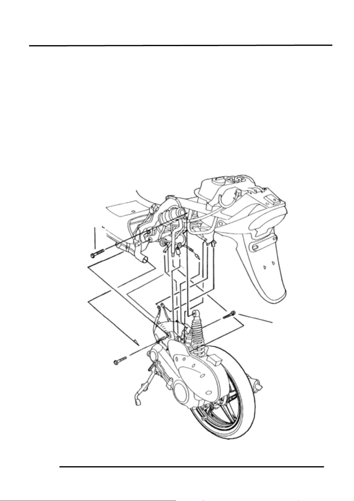
Remove the rear brake adjusting nut and
disconnect the brake cable from the
crankcase.
Remove the rear brake cable clamp and rear
brake cable.
Remove the cooling air tube band on the left
crankcase cover and disconnect the cooling
air tube.
Remove the rear shock absorber lower
mount bolt.
Remove the right and left engine mounting
nuts.
Take out the right and left engine mounting
bolts.
Lift the frame upward to separate it from
the engine and be careful not to damage the
rear fender.
ENGINE HANGER BRACKET REMOVAL
Remove the engine hanger bracket bolt and
engine hanger bracket.
The installation sequence is the reserve of
removal.
Torque: 3.5_ 4.5kg-m
Engine Mounting Nuts
Rear Brake Cable
Clamp
Rear Shock Absorber Lower Mount Bolt
Engine Hanger Bracket Bolt
Engine Hanger Bracket
Page 5

5. ENGINE REMOVAL/INSTALLATION
5-4
ENGINE HANGER BRACKET
INSPECTION
Inspect the stopper rubbers and bushings
for damage and replace with new ones if
necessary.
ENGINE INSTALLATION
Install the engine in the reverse order of
removal.
Torque Values:
Engine mounting bolt : 4.5_ 5.5kg-m
Rear shock absorber lower mount bolt:
: 2.4_ 3.0kg-m
Perform the following inspections and
adjustments after installation.
• Throttle cable
• Oil pump control cable (!3-11)
• Rear brake cable (!3-5)
• Oil pump bleeding (!3-11)
Cables and wires should be routed
properly.
*
Bushings
Engine Hanger
Stopper Rubbers
 Loading...