

Page 1

5. ENGINE REMOVAL/INSTALLATION
5-0
PEO PLE 25 0
5
__________________________________________________________________________________
__________________________________________________________________________________
__________________________________________________________________________________
__________________________________________________________________________________
__________________________________________________________________________________
ENGINE REMOVAL/INSTALLATION
__________________________________________________________________________________
SERVICE INFORMATION -------------------------------------------- 5-1
ENGINE REMOVAL --------------------------------------------------- 5-2
ENGINE INSTALLATION -------------------------------------------- 5-5
ENGINE HANGER REMOVAL --------------------------------------- 5-4
5
Page 2

5. ENGINE REMOVAL/INSTALLATION
5-1
PEO PLE 250
SERVICE INFORMATION
GENERAL INSTRUCTIONS
• A floor jack or other adjustable support is required to support and maneuver the engine. Be
careful not to damage the motorcycle body, cables and wires during engine removal.
• Use shop towels to protect the motorcycle body during engine removal.
• Drain the coolant before removing the engine.
• After the engine is installed, fill the cooling system with coolant and be sure to bleed air from the
water jacket. Start the engine to check for coolant leaks.
• Before removing the engine, the rear brake caliper must be removed first. Be careful not to bend
or twist the brake fluid tube.
SPECIFICATIONS
Engine oil capacity: at disassembly: 1.1 liter
TORQUE VALUES
Rear shock absorber upper mount bolt 35_ 45N-m
Rear shock absorber lower mount bolt 35_ 45N-m
Rear axle nut 110_ 130N-m
Engine hanger bolt (frame side) 45_ 55N-m
Engine hanger bolt (ENG. side) 45_ 55N-m
Rear caliper holder bolt 29_ 35N-m
Exhaust muffler pipe nut 18_ 22N-m
Exhaust muffler bolt 32_ 38N-m
Rear fork bolt 29_ 35N-m
Page 3
5. ENGINE REMOVAL/INSTALLATION
5-2
PEO PLE 250
ENGINE REMOVAL
Drain the coolant. (
!3-9)
Remove the met-in box, carrier. (
!2-6
)
Remove the frame body cover, center cover
and rear fender A together. (
!2-6
)
Remove the exhaust muffler. (
!2-10
)
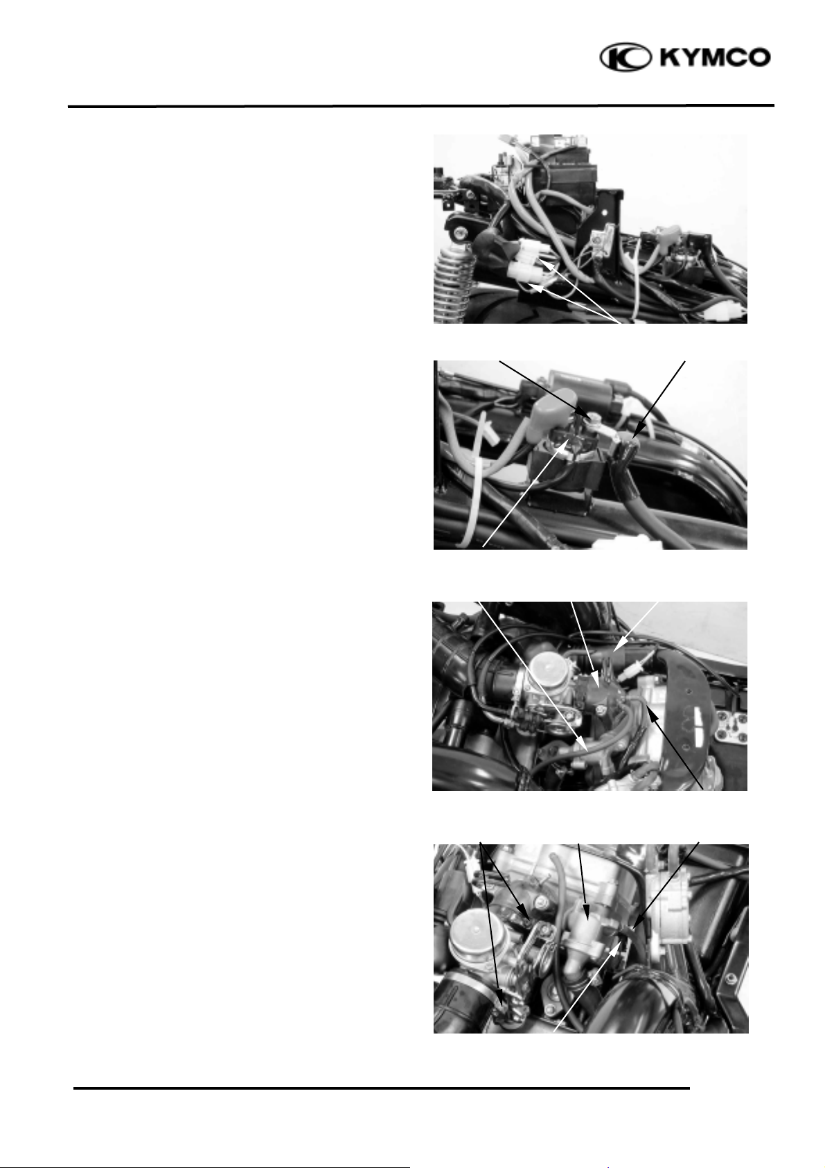
Disconnect all of the A.C. generator.
Remove the nut to disconnect the starter
motor wire that goes to the starter relay.
Disconnect the secondary air vacuum tube
and fuel pump vacuum tube from inlet pipe.
Disconnect the air inlet hose (v-belt chamber)
from frame.
Loosen the intake manifold band (air cleaner
tube and inlet pipe).
Disconnect the radiator air ventilated tube and
thermosensor wire coupler from thermostat.
Starter Relay
Intake
Manifold
Band
Fuel Pump Vacuum Tube
A.C. Generator Wire Connectors
Nut
Starter Motor Wire
Secondary Air
Vacuum Tube
Air Inlet Hose
(V-belt Chamber)
Inlet Pipe
Thermosensor Wire Coupler
Radiator Air
Ventilated Tube
Thermostat
Page 4

5. ENGINE REMOVAL/INSTALLATION
5-3
PEO PLE 250
Disconnect the engine oil pressure switch
wire.
Loosen the water hose bands to disconnect
water hoses from the water ducts.
Disconnect the secondary air tube from the
secondary air inlet tube.
Disconnect the breather hose (air cleaner)
from cylinder head cover.
Disconnect the spark plug cap from cylinder
head.
Remove the screw attaching rear fender C.
Remove the three bolts on the air cleaner.
Remove the air cleaner and disconnect
breather hose from transmission case cover.
Remove the right/left rear shock absorber
upper mount bolts.
Remove the left rear shock absorber lower
mount bolts.
Spark Plug Cap
Bolts
Water Hoses
Water Ducts
Water Hose Bands
Secondary Air Tube
Breather Hose (Cylinder
Head Cover)
Breather Hose
Upper Mount Bolts
Lower Mount Bolts
Rear Shock Absorber
Engine Oil Pressure
Switch Wire
Page 5

5. ENGINE REMOVAL/INSTALLATION
5-4
PEO PLE 250
Remove the left rear shock absorber.
Remove the right rear shock absorber lower
mount bolts.
Remove the right rear shock absorber.
Remove the rear wheel nut.
Disconnect the rear brake fluid tube from the
guide.
Remove the four bolts on the rear fork to
remove rear brake caliper and rear fork.
Remove the bolt to disconnect the engine
negative cable.
Remove the engine mounting nut.
Remove the two nuts of the right and left
step bar.
Remove the right and left step bar.
Nut
Bolts
Bolt
Rear Shock Absorber
Rear Fork
Brake Fluid Tube
Bolt
Engine Mounting Nut
Nuts
Nuts
Step Bar
Step Bar
Engine Negative Cable
Page 6

5. ENGINE REMOVAL/INSTALLATION
5-5
PEO PLE 250
Remove the engine mounting bolt and pull out
the engine.
ENGINE INSTALLATION
Reverse the “REMOVAL” procedures.
ENGINE HANGER REMOVAL
Remove met-in box and carrier. (
!2-6
)
Remove the body cover, center cover and rear
fender A together. (!2-6)
Remove air cleaner. (!5-3)
Remove the two nuts of the right and left
step bar.
Remove the right and left step bar.
Remove the engine mounting nut and engine
hanger bolt (left side).
Remove the engine mounting bolt and engine
hanger bolt (right side).
Remove the starter motor. (
!18-3
)
Remove the engine hanger.
Engine Mounting Bolt
Nuts
Nuts
Step Bar
Step Bar
Engine Mounting Nut
Bolt
Engine Mounting Bolt
Bolt
Apply grease onto the O-rings, oil seals
and bush).
*
Page 7

5. ENGINE REMOVAL/INSTALLATION
5-6
PEO PLE 250
Inspect the engine hanger bushings and stopper
rubber for wear or damage.
INSTALLATION
Reverse the “REMOVAL” procedures.
Bushing
Apply grease onto the bush.
*
 Loading...