

Page 1

10. A.C. GENERATOR/STARTER CLUTCH
10-0
PEO PLE 25 0
10
__________________________________________________________________________________
__________________________________________________________________________________
__________________________________________________________________________________
__________________________________________________________________________________
__________________________________________________________________________________
A.C. GENERATOR/STARTER CLUTCH
__________________________________________________________________________________
SCHEMATIC DRAWING ---------------------------------------------- 10-1
SERVICE INFORMATION -------------------------------------------- 10-2
TROUBLESHOOTING ------------------------------------------------- 10-2
RIGHT CRANKCASE COVER REMOVAL-------------------------- 10-3
STATOR REMOVAL --------------------------------------------------- 10-3
FLYWHEEL REMOVAL----------------------------------------------- 10-4
STARTER CLUTCH ---------------------------------------------------- 10-4
FLYWHEEL INSTALLATION---------------------------------------- 10-8
STATOR INSTALLATION -------------------------------------------- 10-9
RIGHT CRANKCASE COVER INSTALLATION------------------- 10-9
10
Page 2
10. A.C. GENERATOR/STARTER CLUTCH
10-1
PEO PLE 250
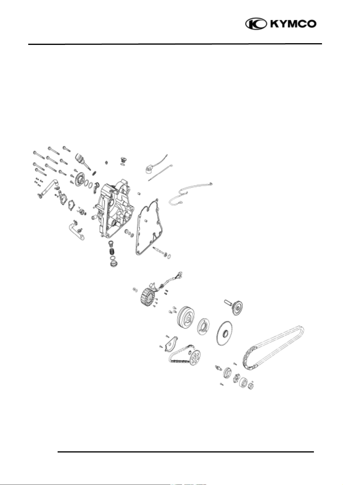
SCHEMATIC DRAWING
Page 3

10. A.C. GENERATOR/STARTER CLUTCH
10-2
PEO PLE 250
SERVICE INFORMATION
GENERAL INSTRUCTIONS
• All servicing operations and inspections in this section can be made with the engine installed.
• Drain the coolant before removing the right crankcase cover.
• Be careful not to drain the coolant when the engine temperature is high. (Perform this operation
when the engine is cold.)
• Drain the coolant into a clean container.
• Drain the engine oil into a clean container before removing the right crankcase cover.
• When the right crankcase cover is installed, fill with the recommended engine oil and coolant.
Then, bleed air from the water jacket.
SPECIFICATIONS
Engine oil: SAE15W/40#
API-SJ
Oil capacity at change: 0.9 liter
Coolant: distilled water + coolant concentrate
SPECIAL TOOLS
Flywheel puller E003
Flywheel holder E021
SPECIFICATIONS
Item
Standard (mm)
Service Limit (mm)
Starter driven gear I.D.
22.026_ 22.045
22.15mm
Starter driven gear O.D.
42.195_ 42.208
41.5mm
TORQUE VALUES
Flywheel nut : 53.9_ 63.7N-m
TROUBLESHOOTING
Refer to page 1-19 for A.C. generator troubleshooting.
Starter motor rotates but engine does not start
• Faulty starter clutch
• Starter motor rotates reversely
• Weak battery
Page 4
10. A.C. GENERATOR/STARTER CLUTCH
10-3
PEO PLE 250
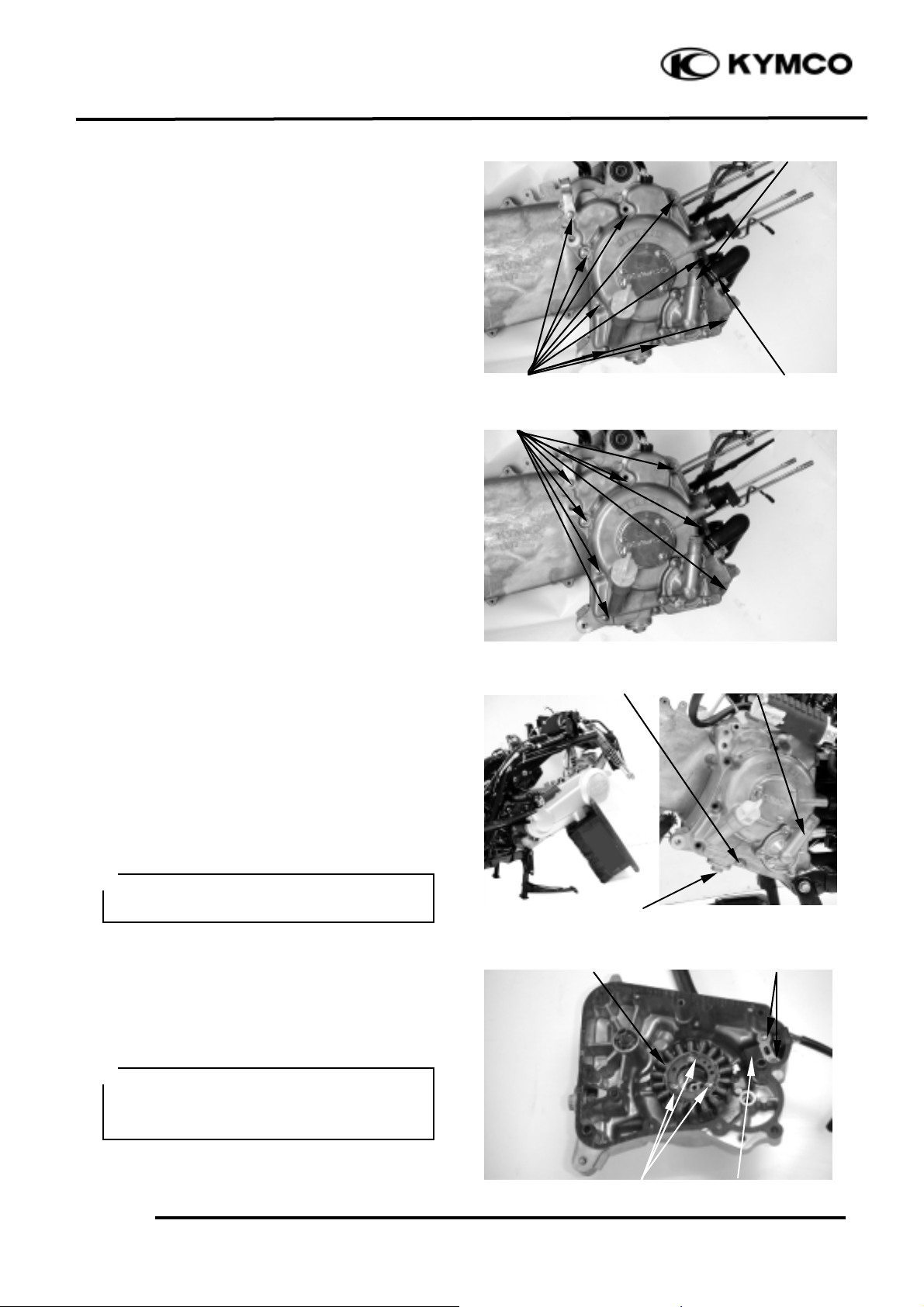
RIGHT CRANKCASE COVER
REMOVAL
Disconnect the water hoses from the water
pump cover. (
!chapter 5
)
Disconnect the water hoses from the right
crankcase cover.
Remove the nine bolts attaching the right
crankcase cover and the cover.
Remove right crankcase cover.
RIGHT CRANKCASE COVER
REMOVAL(ENGINE INSTALLED)
Remove met-in box and frame body cover.
(
!2-6
)
Disconnect the water hoses from the water
pump cover. (
!chapter 5
)
Disconnect the water hoses from the right
crankcase cover. (
!chapter 5
)
Disconnect A.C. generator wire coupler and
oil pressure switch wire. (
!chapter 5
)
Remove the eight bolts attaching the right
crankcase cover and the cover.
Remove the left and right rear shock absorber
lower mount bolts. (
!chapter 5
)
Elevate the back of engine as possible by
placing a suitable stand under the back of
engine.
Remove the bolt between water pump cover
and oil filter screen cap.
Remove right crankcase cover.
STATOR REMOVAL
Remove the two pulser coil attaching screws
and the pulser coil.
Remove the three A.C. generator stator bolts
and the stator.
Water Hose
Bolts
Water Pump Cover
Screws
Bolts
Pulser Coil
A.C. Generator Stator
Bolts
When removing the pulser coil and
stator, be careful not to damage them to
avoid shorted or broken wire.
*
Bolt
Water Pump Cover
Oil Filter Screen Cap
Support the machine securely so there is
no danger of it falling over.
*
Page 5
10. A.C. GENERATOR/STARTER CLUTCH
10-4
PEO PLE 250
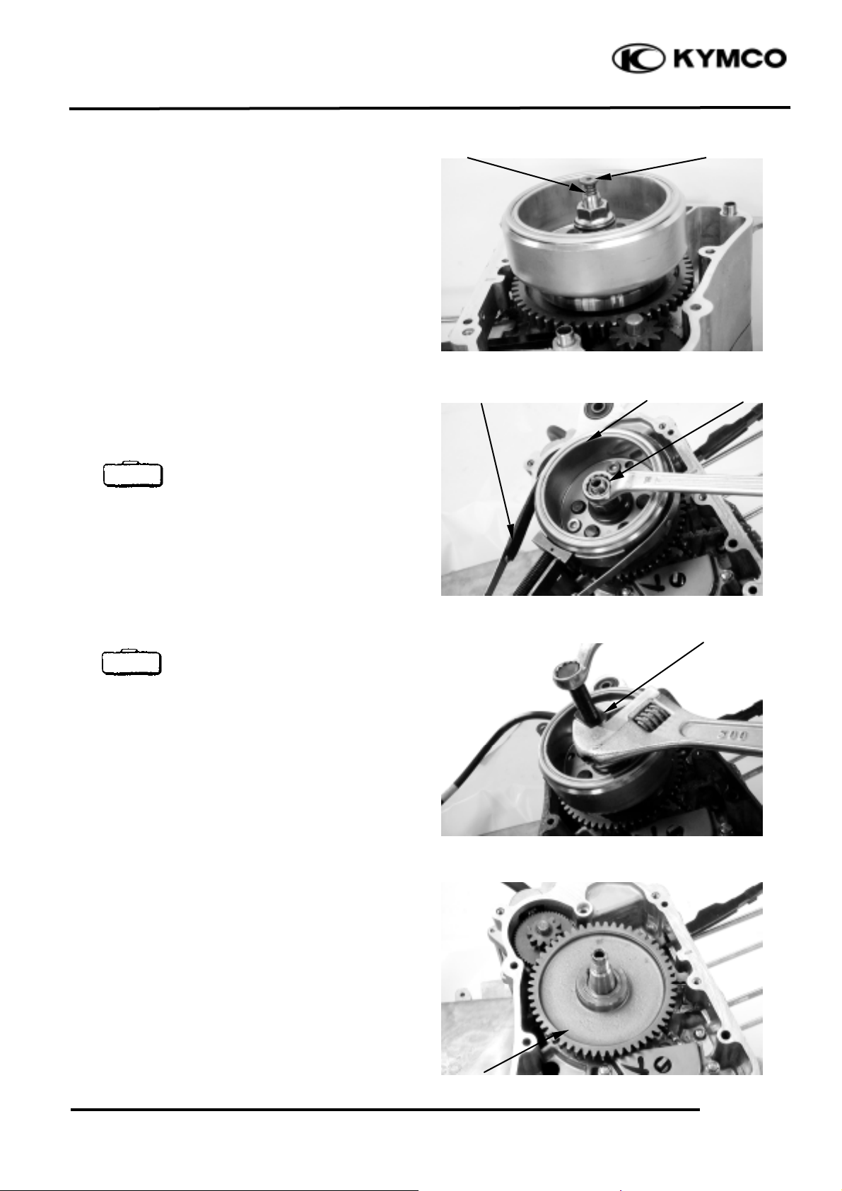
Remove the oil through and spring.
FLYWHEEL REMOVAL
Hold the flywheel with a flywheel holder and
remove the flywheel nut and washer.
Flywheel holder E021
Remove the flywheel with a flywheel puller.
Flywheel puller E003
STARTER CLUTCH
REMOVAL
Remove the starter driven gear.
Flywheel
Nut
Flywheel Holder
Starter Driven Gear
Flywheel Puller
Oil Through
Spring
Special
Special
Page 6
10. A.C. GENERATOR/STARTER CLUTCH
10-5
PEO PLE 250
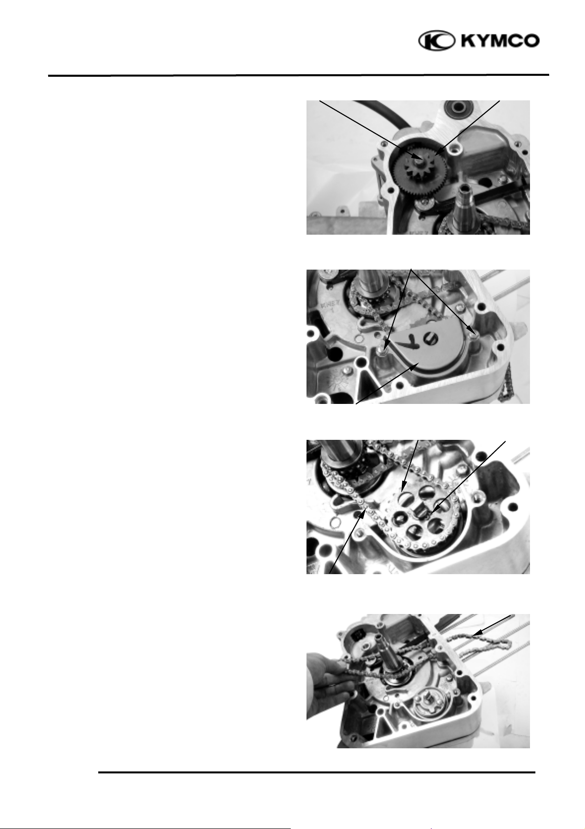
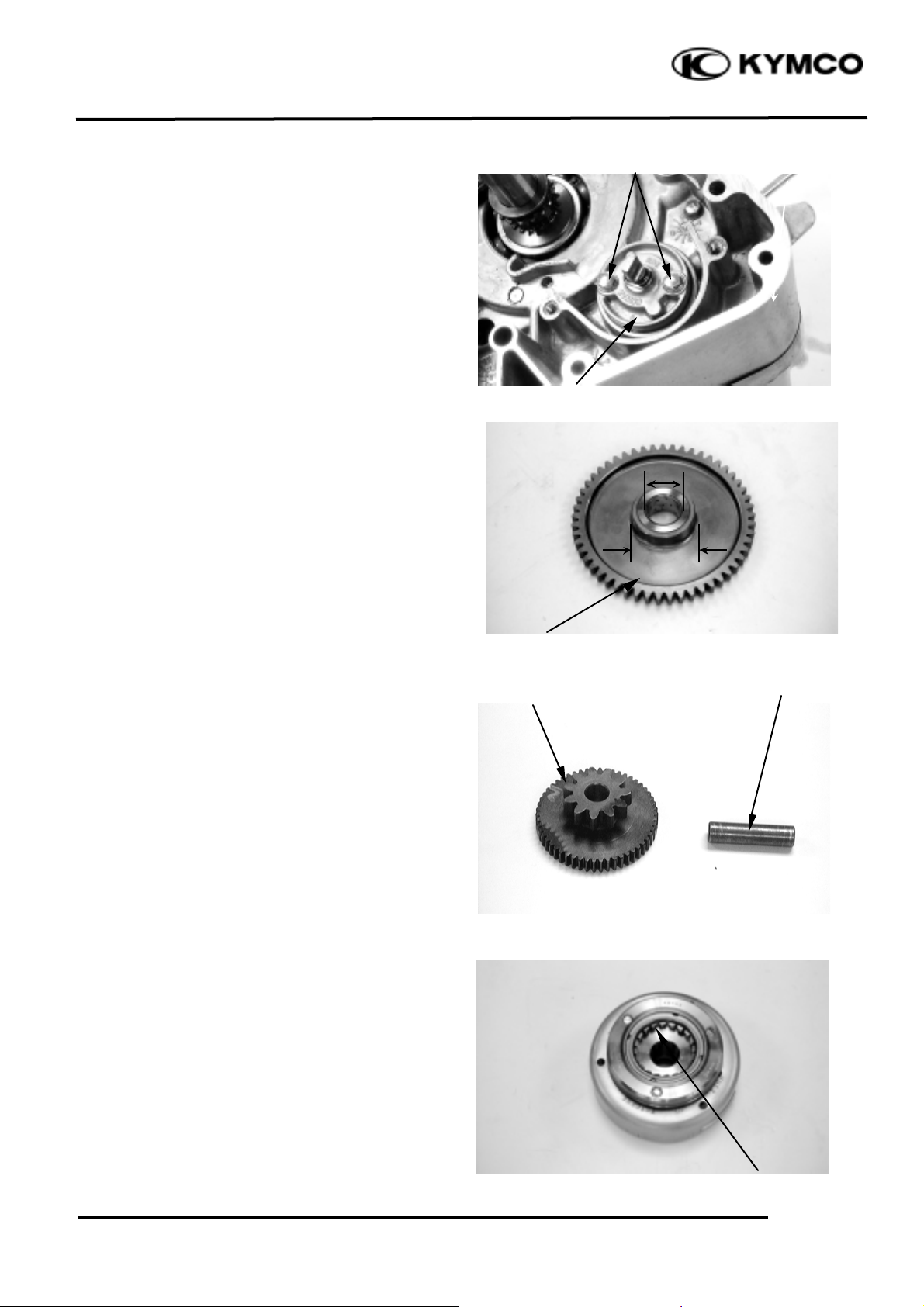
Remove the starter idle gear and shaft.
OIL PUMP REMOVAL
Remove the attaching bolts and oil separator
cover.
Pry the circlip off and remove the oil pump
driven gear, then remove the oil pump drive
chain.
Remove the cam chain.
Circlip
Shaft
Cam Cain
Starter Idle Gear
Bolts
Oil Separator Cover
Oil Pump Driven Gear
Oil Pump Drive chain
Page 7
10. A.C. GENERATOR/STARTER CLUTCH
10-6
PEO PLE 250
Remove the two oil pump bolts to remove
the oil pump.
INSPECTION
Inspect the starter driven gear for wear or
damage.
Measure the starter driven gear I.D. and
O.D.
Service Limits:
I.D. : 22.15mm replace if over
O.D. : 41.50mm replace if below
Inspect the starter idle gear and shaft for
wear or damage.
Inspect the starter one-way clutch for wear
or damage.
Starter Idle Gear
Shaft
Starter Driven Gear
Oil Pump
Bolts
Starter One-way Clutch
Page 8

10. A.C. GENERATOR/STARTER CLUTCH
10-7
PEO PLE 250
Pump Driven Gear
Circlip
Oil Separator Cover
Bolts
INSTALLATION
Install oil pump and tighten the two bolts.
Make sure that the pump shaft rotates
freely.
The arrow of oil pump is upside.
Install cam chain.
Install the pump drive chain and driven gear,
then set the circlip securely on the pump
shaft.
Install the oil separator cover properly.
Bolts
Cam Chain
Oil Pump
Pump Drive Chain
Arrow Mark
Fit the tab of the separator cover into the
slit in the separator.
*
Page 9
10. A.C. GENERATOR/STARTER CLUTCH
10-8
PEO PLE 250
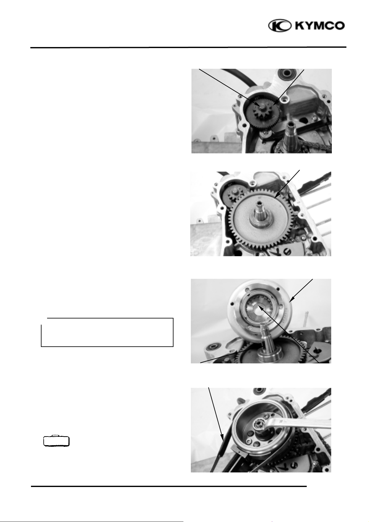
Install the starter idle gear and shaft.
Install the starter driven gear onto the
crankshaft.
FLYWHEEL INSTALLATION
Install the flywheel onto the crankshaft by
aligning the key on the crankshaft with the
groove in the flywheel.
Install washer and nut.
Hold the flywheel with the flywheel holder
and tighten the flywheel nut.
Torque: 53.9_ 63.7N-m
remove the flywheel nut and washer.
Flywheel holder E021
Starter Driven Gear
Starter Idle Gear
Groove
Shaft
Flywheel
Key
Flywheel Holder
• Before installation, check and make
sure that the inside of the flywheel is
not contaminated.
*
Special
Page 10

10. A.C. GENERATOR/STARTER CLUTCH
10-9
PEO PLE 250
STATOR INSTALLATION
Install the A.C. generator stator on the right
crankcase cover and secure it with the three
bolts.
Install the pulser coil on the right crankcase
cover and secure it with the two screws.
Install the wire grommet in the groove in the
right crankcase cover securely.
RIGHT CRANKCASE COVER
INSTALLATION
Install the two dowel pins and a new gasket.
Install the right crankcase cover over the
crankcase, aligning the water pump shaft
groove with the oil pump shaft.
Tighten the nine right crankcase cover bolts.
Connect the water hoses to the right
crankcase cover and water pump cover.
Add the recommended engine oil. (!4-3)
Fill the cooling system with the specified
coolant. (!3-9)
Screws
A.C. Generator Stator
Pulser Coil
Dowel Pins
Gasket
Right Crankcase Cover
Oil Pump Shaft
Water Pump Shaft
Screws
• Be sure to bleed air from the water
jacket after filling the coolant.
*
Be sure to route the stator wire under the
pulser coil.
*
 Loading...