

Page 1
17. LIGHTS/INSTRUMENTS/SWITCHES
17-0
PEO PLE 12 5/ 15 0
17
LIGHTS/INSTRUMENTS/SWITCHES
ELECTRICAL EQUIPMENT LAYOUT ........................................ 17-1
SERVICE INFORMATION........................................................ 17-2
TROUBLESHOOTING.............................................................. 17-2
HEADLIGHT ............................................................................ 17-3
FRONT TURN SIGNAL LIGHT ................................................ 17-3
POSITION/REAR TURN SIGNAL LIGHT..................................... 17-3
IGNITION SWITCH.................................................................. 17-4
HANDLEBAR SWITCH ............................................................ 17-4
STOP SWITCH ......................................................................... 17-6
HORN ....................................................................................... 17-6
FUEL GAUGE........................................................................... 17-6
FUEL UNIT............................................................................... 17-6
AUTO BYSTARTER.................................................................. 17-7
INSTRUMENTS ........................................................................ 17-8
17
Page 2
17. LIGHTS/INSTRUMENTS/SWITCHES
17-1
PEO PLE 125/15 0
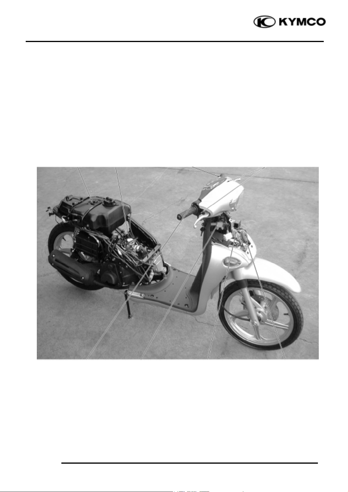
Turn Signal Switch
Stop Switches
Horn Button
ELECTRICAL EQUIPMENT LAYOUT
Headlight
Dimmer Switch
Fuel Unit
Starter Button
Ignition Switch
Auto Bystarter
Headlight Switch
Auto
Bystarter
Horn
Page 3

17. LIGHTS/INSTRUMENTS/SWITCHES
17-2
PEO PLE 125/15 0
SERVICE INFORMATION
GENERAL INSTRUCTIONS
• An electric tester is needed to measure or test the electric equipment.
• Be sure to use fuses and bulbs of the same specifications to avoid damage of electrical equipment.
• After installation of each switch, a continuity check must be performed. A continuity check can
usually be made without removing the part from the motorcycle.
TROUBLESHOOTING
Lights do not come on and horn does not Engine starts but stalls during idling
sound when ignition switch is “ON”
•Faulty auto bystarter
• Faulty ignition switch • Faulty auto bystarter resistor
• Fuse burned out • Poorly connected or broken wire
• Weak battery • Clogged carburetor
• Burned bulb
• Faulty switch
• Faulty horn
• Poorly connected, broken or shorted wire
Fuel gauge pointer does not register
Fuel gauge pointer does not move correctly
• Faulty fuel gauge • Faulty fuel gauge
• Faulty fuel unit • Faulty fuel unit
• Poorly connected, broken or shorted wire • Faulty fuel unit float
Page 4

17. LIGHTS/INSTRUMENTS/SWITCHES
17-3
PEO PLE 125/15 0
HEADLIGHT
BULB REPLACEMENT
Remove the handlebar front cover. (!2)
Remove the rubber boot from the bulb socket.
Remove the bulb socket by turning it counterclockwise.
Remove the bulb for replacement.
Install a new bulb, aligning the groove on the
bulb socket with the tab on the bulb.
Install the bulb socket.
Install the rubber boot.
Install the front cover. (!2)
HEADLIGHT REMOVAL
Remove the handlebar front cover. (!2)
Remove the two screws attaching the
headlight.
Remove the headlight unit.
Remove adjust the headlight beam bolt.
The installation sequence is the reverse of
removal.
After installation, adjust the headlight beam.
(!3-9)
FRONT TURN SIGNAL LIGHT
Remove the turn signal bulb shell screw. (!2)
Remove the front turn signal bulb socket and
replace the bulb.
The installation sequence is the reverse of
removal.
POSITION LIGHT/REAR TURN
SIGNAL LIGHT
BULB REPLACEMENT
Remove the bulb shell screw.
The installation sequence is the reverse of
removal.
Screw
Bulb Socket
Rubber Boot
Screws
Turn Signal Bulb Shell
Position Light Shell
Bolt
Page 5

17. LIGHTS/INSTRUMENTS/SWITCHES
17-4
PEO PLE 125/15 0
IGNITION SWITCH
INSPECTION
Remove the front cover. (!2-4)
Disconnect the ignition switch wire coupler.
Check for continuity between the wire
terminals.
Replacement
Remove the two mounting bolts to remove
the ignition switch holder.
Remove the two screws to remove the
ignition switch for replacement.
HANDLEBAR SWITCHES
HEADLIGHT SWITCH INSPECTION
Remove the handlebar front and rear covers.
(!2-4)
Disconnect the headlight switch wire
couplers. Check for continuity between the
wire terminals.
Ignition Switch Coupler
Ignition Switch Bolts
Headlight Switch
Page 6

17. LIGHTS/INSTRUMENTS/SWITCHES
17-5
PEO PLE 125/15 0
STARTER SWITCH
HORN SWITCH
TURN SIGNAL SWITCH
DIMMER SWITCH
Horn Button
Turn Signal Switch
Starter Switch
Dimmer Switch
Headlight Switch
Sky
Page 7

17. LIGHTS/INSTRUMENTS/SWITCHES
17-6
PEO PLE 125/15 0
STOP SWITCH
INSPECTION
Remove the handlebar front cover. (!2)
Disconnect the front stop switch wire
coupler.
Check for continuity between the wire
terminals when the front brake lever is
applied. The switch is normal if there is
continuity.
HORN INSPECTION
Remove the front cover. (!2)
Disconnect the horn wire coupler.
The horn is normal if it sounds when a 12V
battery is connected across the horn wire
terminals.
FUEL GAUGE
INSPECTION
Remove the rear right side cover. (!2)
Disconnect the fuel gauge wire connector.
Turn the ignition switch ON.
Connect the green and yellow/white wires and
the fuel gauge needle should move from E to
F.
Connect the green and blue/white wires and
the fuel gauge needle should move from F to
E.
FUEL UNIT
REMOVAL
Remove the met-in box. (!2)
Remove the rear right side cover. (!2)
Disconnect the fuel unit wire connector.
Remove the fuel unit.
Fuel Unit Connector
Be careful not to bend or damage the fuel
unit float arm.
*
Page 8

17. LIGHTS/INSTRUMENTS/SWITCHES
17-7
PEO PLE 125/15 0
INSPECTION
Measure the resistance between the fuel unit
wire terminals with the float at upper and
lower positions.
RESISTANCES Unit: W
Float
Color
Upper
Lower
G_ Y/W
26_ 38
450_ 550
G_ L/W
450_ 550
26_ 38
Y/W_ L/W
450_ 550
450_ 550
The installation sequence is the reverse of
removal.
AUTO BYSTARTER
AUTO BYSTARTER INSPECTION
Remove the rear right side cover. (!2)
Disconnect the auto bystarter wire connector.
Measure the resistance between the yellow
and green/black wire terminals.
Resistance: 10W max.
RESISTOR INSPECTION
Remove the front cover. (!2)
Disconnect the green/black and green wires
and measuring the resistance between the wire
terminals.
Resistance: 5W max.
If the needle remains at “•”, it indicates that
the resistor is faulty and must be replaced.
• Install the fuel unit by aligning the
groove on the fuel unit with the tab on
the fuel tank.
Perform this operation when the engine
is cold.
*
Auto Bystarter
Auto Bystarter Resistor
Page 9

17. LIGHTS/INSTRUMENTS/SWITCHES
17-8
PEO PLE 125/15 0
INSTRUMENTS
BULB REPLACEMENT
Remove the front cover. (!2)
Remove the bulb socket and replace the bulb.
The installation sequence is the reverse of
removal.
INSTRUMENTS REPLACEMENT
Remove the handlebar front cover. (!2)
Remove the handlebar rear cover. (!2)
Disconnect the right and left handlebar
switches wire couplers.
Disconnect the speedometer cable.
Remove the instrument bulb sockets
Disconnect the three fuel gauge wires.
Remove the instrument wire clamp screw.
Remove the three screws attaching the
instruments to the handlebar rear cover.
Remove the instruments.
ASSEMBLY/INSTALLATION
The assembly and installation sequence is the
reverse of removal.
Clamp
Bulb Socket
Speedometer Cable
Bulb Socket
Screws
Instruments
Fuel Gauge Wires
Dimmer/
Passing Wires
Lighting/
Start Wires
Stop Light
Wires
Turn Signal
Wires
Clamp
Page 10

17. LIGHTS/INSTRUMENTS/SWITCHES
17-9
PEO PLE 125/15 0
DISASSEMBLY
Remove the screws to disassemble the instruments.
 Loading...