

Page 1
2. FRAME COVERS/EXHAUST MUFFLER
2-0
PEO PL E 12 5/15 0
2
FRAME COVERS/EXHAUST MUFFLER
FRAME COVERS LAYOUT------------------------------------------ 2-1
SERVICE INFORMATION ------------------------------------------- 2-2
TROUBLESHOOTING ------------------------------------------------ 2-2
FRAME COVERS ------------------------------------------------------ 2-4
2
Page 2
2. FRAME COVERS/EXHAUST MUFFLER
2-1
PEO PL E 12 5/15 0
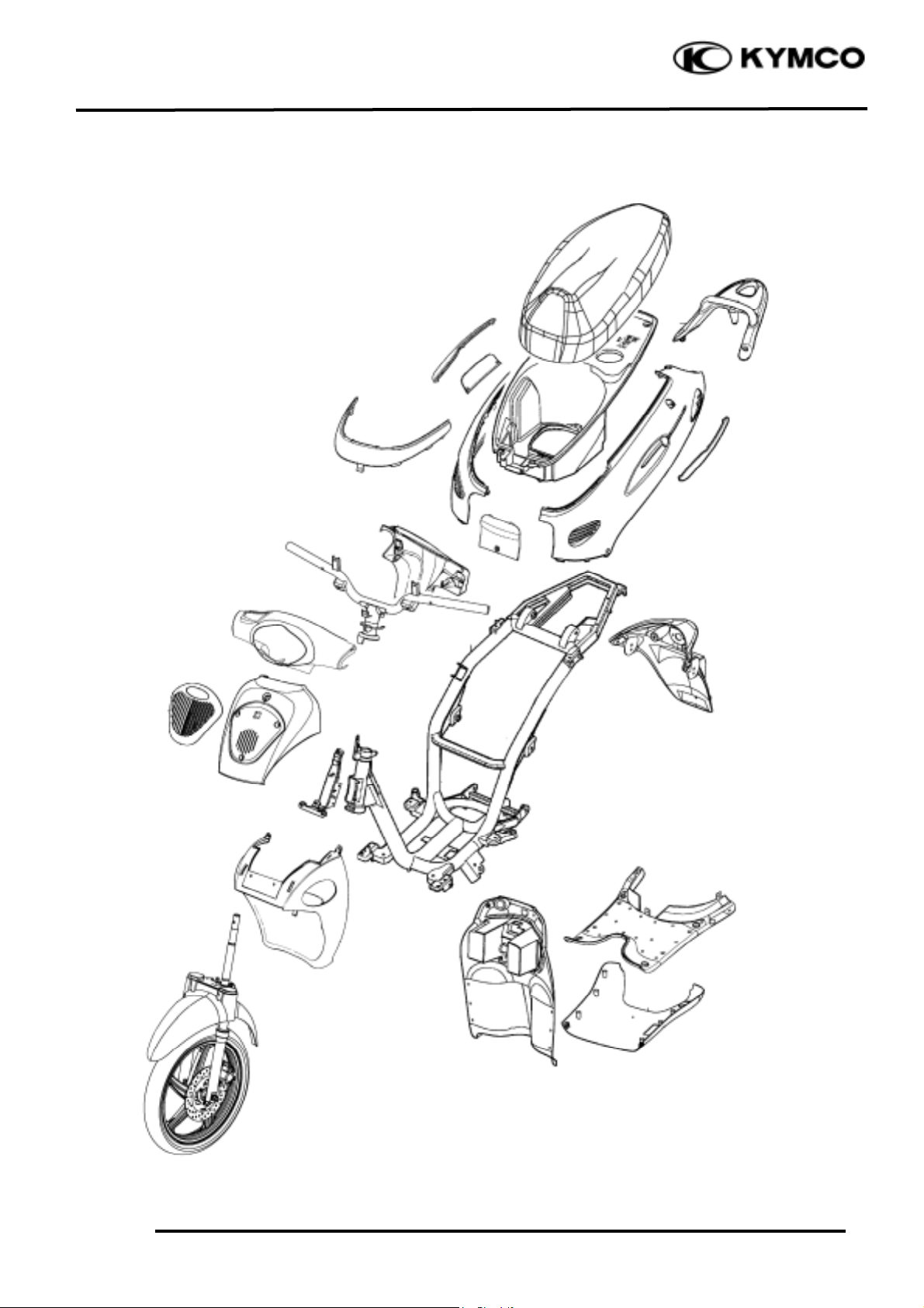
FRAME COVERS LAYOUT
Page 3
2. FRAME COVERS/EXHAUST MUFFLER
2-2
PEO PL E 12 5/15 0
SERVICE INFORMATION
GENERAL INSTRUCTIONS
• When removing frame covers, use special care not to pull them by force because the cover joint
claws may be damaged.
• Make sure to route cables and harnesses according to the Cable & Harness Routing.
TORQUE VALUES
Exhaust muffler lock bolt 3.5kg-m
Exhaust muffler joint lock nut 1.2kg-m
TROUBLESHOOTING
Noisy exhaust muffler
• Damaged exhaust muffler
• Exhaust muffler joint air leaks
Lack of power
• Caved exhaust muffler
• Exhaust muffler air leaks
• Clogged exhaust muffler
Page 4

2. FRAME COVERS/EXHAUST MUFFLER
2-3
PEO PL E 12 5/15 0
Page 5

2. FRAME COVERS/EXHAUST MUFFLER
2-4
PEO PL E 12 5/15 0
FRAME COVERS
(1) REAR HAND GRIP REMOVAL
Remove the three bolts attaching the rear hand
grip.
Remove the rear hand grip.
(2) MET-IN BOX REMOVAL
Remove the three bolts and two nuts
attaching the met-in box.
Remove the met-in box.
(3) REAR FENDER REMOVAL
Remove the screw on each side of the rear
fender.
Remove (3-1) the two nuts attaching the rear
fender.
Remove the rear fender.
Remove (3-2) the license light wire connector.
(4) UNDER COVERS REMOVAL
Remove the frame center cover screws.
Remove the two screws attaching the part of
the frame body cover.
Remove (4-2) taillight rear turn signal light
wire connector.
(5) BOTTOM COVER REMOVAL
Remove the one bolt attaching each side of the
bottom protector cover.
Remove the bolt on site stand.
(6) FLOOP BOARD REMOVAL
Remove the two bolts attaching the rear floor
board.
Remove (6-1) the four bolts attaching the floor
board.
Remove the six screws attaching the floor
board.
Remove the floor board.
(7) FRONT COVER REMOVAL
Remove the bolt on the front of the front
cover.
Remove the front cover.
Page 6

2. FRAME COVERS/EXHAUST MUFFLER
2-5
PEO PL E 12 5/15 0
Page 7

2. FRAME COVERS/EXHAUST MUFFLER
2-6
PEO PL E 12 5/15 0
(8) FRONT TOOL BOX REMOVAL
Remove the nut attaching the front tool
box.
Remove the ignition switch decorative ring.
Remove (8-1) the six screws that combine
the front cover with the front tool box.
Remove (8-2) the two screws attaching the
front cover.
Remove the front tool box.
(9) HANDLEBAR COVER REMOVAL
Remove the handlebar front cover bolt.
Remove (9-1) the two screws attaching the
handlebar rear cover.
Disconnect the headlight wire connector and
remove the handlebar front cover.
Remove the bolt attaching the handlebar
rear cover.
Remove (9-2) two screws inside the
handlebar rear cover.
The installation sequence the reverse of
removal.
(10) EXHAUST MUFFLER REMOVAL
Remove the two exhaust muffler joint lock
nuts.
Remove (10-1) the two exhaust muffler
lock bolts to remove the exhaust muffler.
Remove the exhaust muffler joint packing
collar.
When installing, first install the exhaust
muffler packing collar onto the engine and
then install the exhaust muffler.
Torques:
Exhaust muffler lock bolt:3.5kg-m
Exhaust muffler joint lock nut:1.2kg-m
 Loading...