

Page 1

5. FUEL SYSTEM
5-0
PEO PLE 12 5/ 15 0
5
FUEL SYSTEM
SERVICE INFORMATION..........................................................5-2
TROUBLESHOOTING ................................................................5-3
CARBURETOR REMOVAL ........................................................5-4
AUTO BYSTARTER....................................................................5-4
AIR CUT-OFF VALVE................................................................5-6
VACUUM CHAMBER .................................................................5-6
FLOAT CHAMBER.....................................................................5-7
CARBURETOR INSTALLATION .............................................. 5-10
FUEL TANK..............................................................................5-11
FUEL UNIT ............................................................................... 5-11
AUTO FUEL VALVE................................................................. 5-12
AIR CLEANER.......................................................................... 5-13
5
Page 2
5. FUEL SYSTEM
5-1
PEO PLE 125/150
FUEL SYSTEM
Page 3
5. FUEL SYSTEM
5-2
PEO PLE 125/150
SERVICE INFORMATION
GENERAL INSTRUCTIONS
• Do not bend or twist control cables. Damaged control cables will not operate smoothly.
• When disassembling fuel system parts, note the locations of O-rings. Replace them with new
ones during assembly.
• Before float chamber disassembly, loosen the drain screw to drain the residual gasoline into a
clean container.
• After the carburetor is removed, plug the intake manifold side with a clean towel to prevent
foreign matters from entering.
• Remove the vacuum diaphragm before cleaning the carburetor air and fuel passages with
compressed air to avoid damaging the vacuum diaphragm.
• When the motorcycle is not used for over one month, drain the residual gasoline from the float
chamber to avoid erratic idling and clogged slow jet due to deteriorated fuel.
• The pilot screw is factory pre-set and no adjustment is necessary. During carburetor
disassembly, note the number of turns of the pilot screw and use as a reference when reinstalling
it.
• A tachometer must be used when adjusting the engine speed.
• Turn the pilot screw in or out slowly to obtain the highest engine speed.
SPECIFICATIONS
125 cc
150 cc
Item
Standard
Standard
Venturi dia. (mm)
22.1
22.1
Identification number
VE052A
VE054A
Float level (mm)
17.5
17.5
Main jet
#108
#110
Slow jet
#35
#35
Idle speed
1700±100rpm
1700±100rpm
Throttle grip free play
2_ 6mm
2_ 6mm
Pilot screw opening
3
3
/8
2
1
/2
SPECIAL TOOL
Float level gauge
Gasoline is very dangerous. When working with gasoline, keep sparks and flames away
from the working area.
Gasoline is extremely flammable and is explosive under certain conditions. Be sure to
work in a well-ventilated area.
*
Page 4

5. FUEL SYSTEM
5-3
PEO PLE 125/150
TROUBLESHOOTING
Engine is hard to start Misfiring during acceleration
• No spark at plug • Faulty ignition system
• Compression too low • Lean mixture
• No fuel to carburetor
-Clogged fuel filter Engine idles roughly, stalls or runs poorly
-Restricted fuel line • Clogged fuel system
-Faulty float valve • Ignition malfunction
-Incorrectly adjusted float level • Rich or lean mixture
• Engine flooded with fuel • Contaminated fuel
-Clogged air cleaner • Intake air leak
-Fuel overflowing • Incorrect idle speed
• Intake air leak • Incorrectly adjusted pilot screw
• Contaminated fuel • Clogged idle system or auto bystarter passages
• Faulty auto bystarter • Incorrectly adjusted float level
• Clogged idle system or auto bystarter passages
Lean mixture
Rich mixture • Clogged fuel jets
• Faulty auto bystarter • Faulty float valve
• Faulty float valve • Float level too low
• Float level too high • Clogged fuel system
• Clogged air jets • Intake air leak
• Dirty air cleaner • Faulty vacuum piston
• Flooded carburetor • Faulty throttle
Backfiring at deceleration
• Faulty air cut-off valve
• Lean mixture in idle system
Page 5
5. FUEL SYSTEM
5-4
PEO PLE 125/150
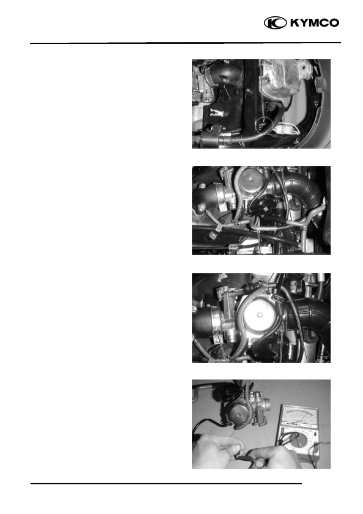
CARBURETOR REMOVAL
Remove the frame body cover. (!2)
Disconnect the auto bystarter wire connector.
Loosen the drain screw and drain the fuel
from the float chamber.
Disconnect the fuel tube and vacuum tube at
the carburetor.
Loosen the throttle cable adjusting nut and
lock nut, and disconnect the throttle cable
from the carburetor.
Loosen the carburetor intake manifold band
and air cleaner connecting tube band screws
and then remove the carburetor.
AUTO BYSTARTER
OPERATION INSPECTION
Measure the resistance between the auto
bystarter wire terminals.
Resistance: 5W max. (10 minutes
minimum after stopping the engine)
If the reading is not within the limit, replace
the auto bystarter with a new one.
Auto Bystarter Wire
Adjusting Nut
Fuel Tube
Intake Manifold
Band
Air Cleaner Connecting
Tube Band
Throttle Cable
Vacuum Tube
Lock Nut
Page 6

5. FUEL SYSTEM
5-5
PEO PLE 125/150
Connect a hose to the fuel enriching circuit of
the carburetor. Connect the auto bystarter
yellow wire to the positive (+) terminal of a
battery and green wire to the negative (-)
terminal. Wait 5 minutes and blow the hose
with mouth or vacuum pump. If the passage
is blocked, the auto bystarter is normal.
Disconnect the auto bystarter from the
battery. Wait 30 minutes and blow the hose
with mouth or vacuum pump. If air can be
blown into the hose, the auto bystarter is
normal.
REMOVAL
Remove the set plate screws and set plate.
Remove the auto bystarter from the
carburetor.
AUTO BYSTARTER INSPECTION
Check the auto bystarter valve and needle for
nicks, wear or damage.
If any faulty part is found, replace the auto
bystarter as a set.
INSTALLATION
Insert the auto bystarter into the carburetor
body until it bottoms.
Position the set plate into the groove in the
auto bystarter and tighten the screws.
• Be sure to install the auto bystarter and
set plate properly.
• Install the set plate with its bottom
face facing down.
*
Auto Bystarter
Screws
Bystarter Needle
Bystarter Valve
Auto Bystarter
Screws
Set Plate
Vacuum Pump
Adopter
Page 7

5. FUEL SYSTEM
5-6
PEO PLE 125/150
AIR CUT-OFF VALVE
DISASSEMBLY
Disconnect the vacuum tube from the air cutoff valve.
Remove the two screws to remove the air cutoff valve cover, spring and vacuum
diaphragm.
ASSEMBLY
Install the vacuum diaphragm onto the
carburetor.
Install the spring and air cut-off valve cover
and then tighten the two screws.
VACUUM CHAMBER
DISASSEMBLY
Remove the two vacuum chamber cover
screws and the cover.
Remove the spring and vacuum diaphragm/
piston.
Spring
Screws
Vacuum Diaphragm
• Be sure to set the vacuum diaphragm
lip into the groove on the carburetor.
• When installing the air cut-off valve
cover, make sure that the vacuum
diaphragm is properly installed.
*
Air Cut-off valve
Cover
Spring
Vacuum Chamber Cover
Air Cut-off valve Cover
Set Plate
Page 8

5. FUEL SYSTEM
5-7
PEO PLE 125/150
Push the needle holder in and turn it left to
remove the needle holder.
Remove the spring and jet needle from the
piston.
INSPECTION
Inspect the needle for stepped wear.
Inspect the vacuum piston for wear or
damage.
Inspect the diaphragm for deterioration and
tears.
ASS EMBLY
Install the vacuum piston/diaphragm in the
carburetor body and align the tab on the
diaphragm with the groove in the carburetor
body.
Install the spring.
Install the vacuum chamber cover and tighten
it with the two screws.
FLOAT CHAMBER
DIS AS SEMBLY
Remove the four float chamber screws and
the float chamber.
Vacuum Chamber Cover
• Be careful not to damage the diaphragm.
• Hold the vacuum piston while
tightening the vacuum chamber cover.
*
Be careful not to damage the vacuum
diaphragm.
*
Vacuum Diaphragm
Vacuum Diaphragm/Piston
Float Chamber
Jet Needle
Vacuum Diaphragm
Install
Remove
Page 9

5. FUEL SYSTEM
5-8
PEO PLE 125/150
Remove the float pin, float and float valve.
INSPECTION
Inspect the float valve and valve seat for
damage or clogging.
Inspect the float valve and valve seat contact
area for stepped wear or contamination.
Remove the main jet, needle jet holder, needle
jet, slow jet and pilot screw.
Clean the removed fuel jets with detergent oil
and blow them open with compressed air.
Blow compressed air through all passages of
the carburetor body.
Pilot Screw
• Be careful not to damage the fuel jets
and pilot screw.
• Before removing, turn the pilot screw
in and carefully count the number of
turns until it seats lightly and then
make a note of this.
• Do not force the pilot screw against its
seat to avoid seat damage.
*
Float Valve
Float
Float Pin
Valve Seat
Also remove and clean the vacuum
chamber and air cut-off valve.
*
Screws
Worn or contaminated float valve and
valve seat must be replaced because it
will result in float level too high due to
incomplete airtightness.
*
Slow Jet
Main Jet
Needle Jet Holder
Needle Jet
Page 10

5. FUEL SYSTEM
5-9
PEO PLE 125/150
ASSEMBLY
Install the slow jet, needle jet, needle jet
holder, main jet and pilot screw.
Standard Opening: 3
3
/8
turns
Install the float valve, float and float pin.
Return the pilot screw to the original
position as noted during removal.
*
Pilot Screw
Slow Jet
Main Jet
Needle Jet Holder
Needle Jet
Page 11

5. FUEL SYSTEM
5-10
PEO PLE 125/150
FLOAT LEVEL INSPECTION
Measure the float level.
Float Level: 18.5mm
Float Level Gauge
CARBURETOR INSTALLATION
Tighten the drain screw.
Install the carburetor onto the intake
manifold, aligning the tab on the carburetor
with the cutout in the intake manifold.
Tighten the band screw.
Install the air cleaner connecting tube and
tighten the band screw.
Connect the throttle cable to the throttle
wheel on the carburetor.
Connect the fuel tube and vacuum tube to the
carburetor.
Connect the auto bystarter wire connector.
Perform the following inspections and
adjustments:
-Throttle grip free play (!3-3)
-Carburetor idle speed (!3-6)
Special
Auto Bystarter Wire
Vacuum Tube
Float Valve
Connecting Tube Band
Throttle Cable
• Check the operation of the float valve
and float before float level inspection.
• Measure the float level by placing the
float level gauge on the float chamber
face parallel with the main jet.
*
Float Level Gauge
Float Pin
Page 12

5. FUEL SYSTEM
5-11
PEO PLE 125/150
FUEL TANK
REMOVAL
Remove the frame body cover.
Disconnect the fuel unit wire connector.
Disconnect the fuel tube and vacuum tube at
the auto fuel valve.
Remove the fuel tank frame mounting bolts
and fuel tank frame.
Remove the four fuel tank mounting bolts and
fuel tank.
INSTALLATION
Install the fuel tank in the reverse order of
removal.
FUEL UNIT
REMOVAL
Disconnect the fuel unit wire connector.
Removal the three bolts on the fuel unit.
Fuel Unit Wire Connector
Fuel Tank
Auto Fuel Valve
Vacuum Tube
Refer to Section 17 for the fuel unit
inspection.
*
Do not bend the fuel unit float arm;
otherwise, the fuel unit metering values
will be incorrect.
*
Bolt
Page 13

5. FUEL SYSTEM
5-12
PEO PLE 125/150
Install the fuel unit.
Connect the fuel unit wire connector.
INSTALLATION
Inspect the fuel unit gasket for damage.
AUTO FUEL VALVE
Disconnect the fuel tube and vacuum tube
from the carburetor.
Connect a vacuum pump to the vacuum tube
and apply vacuum. Check if fuel flows out.
• The valve is operating normally if fuel flows
out of the fuel tube when the vacuum is
applied.
• The fuel shall stop flowing out when the
vacuum pump is disconnected.
If the fuel valve does not operate normally,
Check the vacuum diaphragm for poor
installation or damage and inspect the fuel
tube for clogging.
No Smoking!
*
Auto Fuel Valve
First clean the fuel tube.
*
Make sure that the nick on the retainer is
aligned with the nick on the fuel tank.
*
Nick
Page 14

5. FUEL SYSTEM
5-13
PEO PLE 125/150
AIR CLEANER
Loosen the air cleaner connecting tube band
screw.
Disconnect the transmission case breather
tube from the air cleaner case.
Remove the two bolts and air cleaner case.
The installation sequence is the reverse of
removal.
Air Cleaner Case
Bolt
 Loading...