

Page 1

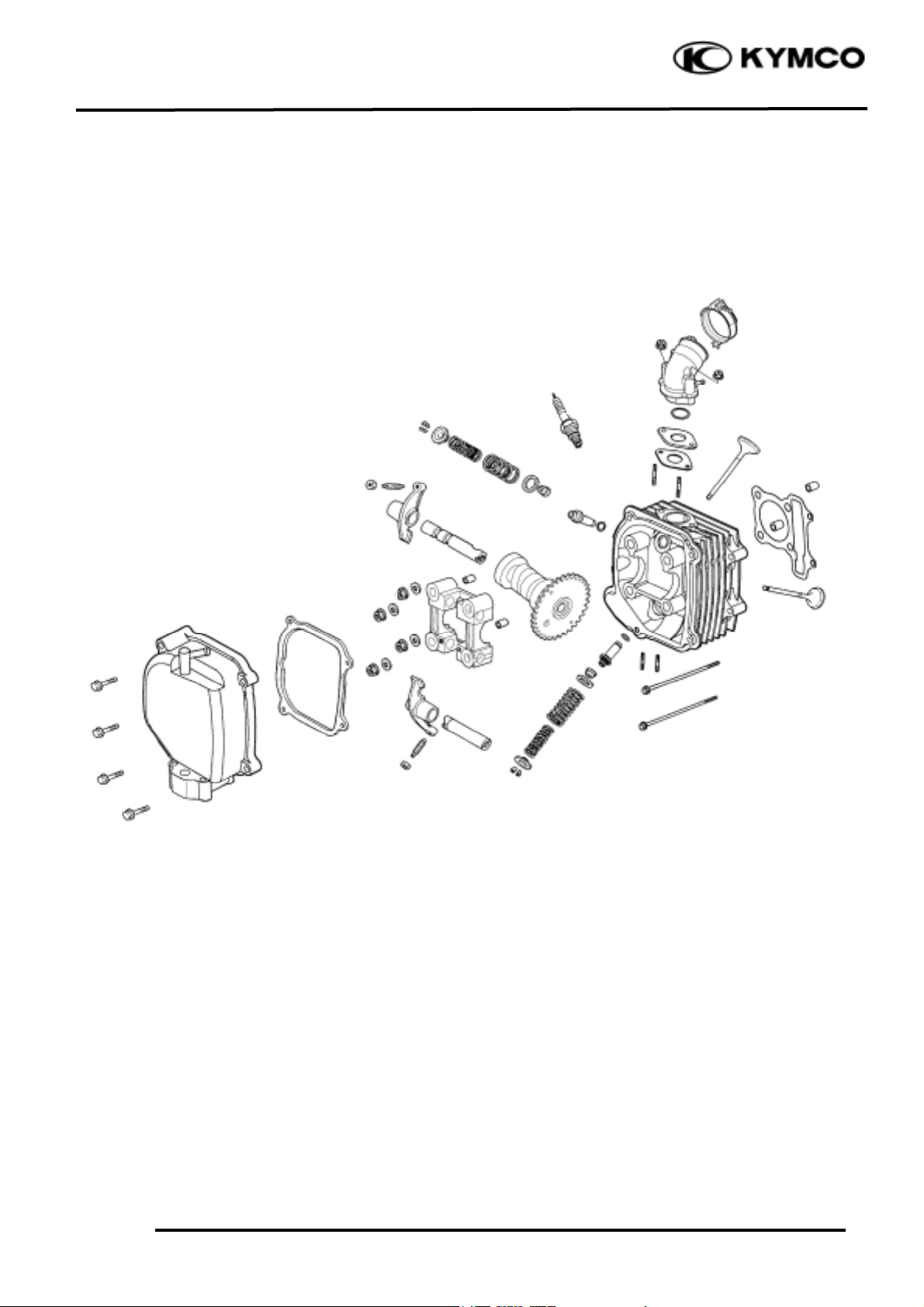
7. CYLINDER HEAD/VALVES
7-0
PEO PLE 12 5/ 15 0
7
CYLINDER HEAD/VALVES
SERVICE INFORMATION..........................................................7-2
TROUBLESHOOTING ................................................................7-3
CAMSHAFT REMOVAL.............................................................7-4
CYLINDER HEAD REMOVAL....................................................7-7
CYLINDER HEAD DISASSEMBLY.............................................7-8
CYLINDER HEAD ASSEMBLY................................................. 7-10
CYLINDER HEAD INSTALLATION .........................................7-10
CAMSHAFT INSTALLATION................................................... 7-11
7
Page 2
7. CYLINDER HEAD/VALVES
7-1
PEO PLE 125/150
0.8kg-m
1.2kg-m
2.0kg-m
Page 3
7. CYLINDER HEAD/VALVES
7-2
PEO PLE 125/150
SERVICE INFORMATION
GENERAL INSTRUCTIONS
• The cylinder head can be serviced with the engine installed in the frame.
• When assembling, apply molybdenum disulfide grease or engine oil to the valve guide movable
parts, valve arm and camshaft sliding surface for initial lubrication.
• The camshaft is lubricated by engine oil through the cylinder head engine oil passages. Clean the
oil passages before assembling the cylinder head.
• After disassembly, clean the removed parts and dry them with compressed air before inspection.
• After removal, mark and arrange the removed parts in order. When assembling, install them in the
reverse order of removal.
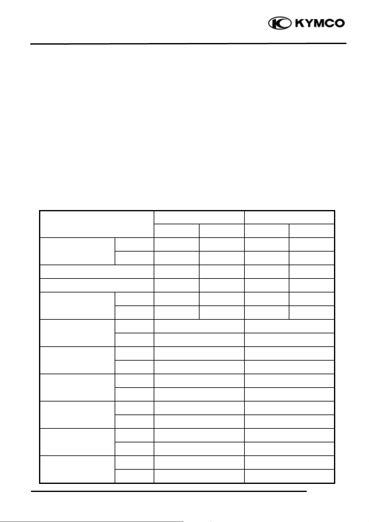
SPECIFICATIONS
Standard (mm)
Service Limit (mm)
Item
125cc
150cc
125cc
150cc
IN
0.10
0.10
-
-
Valve clearance (cold)
EX
0.10
0.10
-
-
Cylinder head compression pressure
13 (kg/cm_)
15 (kg/cm_)
-
-
Cylinder head warpage
---
-
IN
29.7064
29.803
29.3
29.4
Camshaft cam height
EX
29.4251
29.4388
29.15
29.05
IN
10.000-10.015
10.10
Valve rocker arm I.D.
EX
10.00-10.015
10.10
IN
9.972-9.987
9.91
Valve rocker arm shaft
O.D.
EX
9.972-9.987
9.91
IN
1.0
1.8
Valve seat width
EX
1.0
1.8
IN
4.975-4.990
4.90
Valve stem O.D.
EX
4.975-4.990
4.90
IN
5.000-5.012
5.30
Valve guide I.D.
EX
5.000-5.012
5.30
IN
0.10-0.037
0.08
Valve stem-to-guide
clearance
EX
0.030-0.057
0.10
Page 4

7. CYLINDER HEAD/VALVES
7-3
PEO PLE 125/150
TORQUE VALUES
Cylinder head nut 2.0kg-m Apply engine oil to threads
Valve clearance adjusting nut 0.8kg-m Apply engine oil to threads
TROUBLESHOOTING
• The poor cylinder head operation can be diagnosed by a compression test or by tracing engine
top-end noises.
Poor performance at idle speed White smoke from exhaust muffler
• Compression too low • Worn valve stem or valve guide
• Damaged valve stem seal
Compression too low
• Incorrect valve clearance adjustment Abnormal noise
• Burned or bend valves • Incorrect valve clearance adjustment
• Incorrect valve timing • Sticking valve or broken valve spring
• Broken valve spring • Damaged or worn camshaft
• Poor valve and valve seat contact • Worn cam chain guide
• Leaking cylinder head gasket • Worn camshaft and rocker arm
• Warped or cracked cylinder head contact surface
• Poorly installed spark plug
Compression too high
• Excessive carbon build-up in combustion
chamber
Page 5

7. CYLINDER HEAD/VALVES
7-4
PEO PLE 125/150
CAMSHAFT REMOVAL
Remove the center cover.
Remove the four cylinder head cover bolts to
remove the cylinder head cover.
Remove the cam chain tensioner cap screw
and the O-ring.
Turn the cam chain tensioner screw clockwise
to tighten it.
Turn the flywheel counterclockwise so that
the “T” mark on the flywheel aligns with the
index mark on the crankcase to bring the
round hole on the camshaft gear facing up to
the top dead center on the compression
stroke.
Cylinder Head Cover
O-ring
Tensioner Screw
Round Hole
Camshaft Gear
Punch Marks
bolt
Page 6

7. CYLINDER HEAD/VALVES
7-5
PEO PLE 125/150
Remove the four cylinder head nuts and
washers.
Remove the camshaft holder and dowel pins.
Remove the camshaft gear from the cam chain
and remove the camshaft.
CAMSHAFT INSPECTION
Check each cam lobe for wear or damage.
Measure the cam lobe height.
Service Limits:
( 125 cc )
IN : 29.30mm replace if below
EX: 29.15mm replace if below
( 150 cc )
IN : 29.40mm replace if below
EX: 29.05mm replace if below
Cam Chain
Camshaft Gear
Camshaft Holder
Nut
Washer
Dowel Pins
Camshaft
Diagonally loosen the cylinder head nuts
in 2 or 3 times.
*
Page 7

7. CYLINDER HEAD/VALVES
7-6
PEO PLE 125/150
Check each camshaft bearing for play or
damage. Replace the camshaft assembly with
a new one if the bearings are noisy or have
excessive wear.
CAMSHAFT HOLDER DISASSEMBLY
Take out the valve rocker arm shafts using a
5mm bolt.
Remove the valve rocker arms.
CAMSHAFT HOLDER INSPECTION
Inspect the camshaft holder, valve rocker
arms and rocker arm shafts for wear or
damage.
Measure the I.D. of each valve rocker arm.
Service Limits: IN: 10.10mm replace if over
EX: 10.10mm replace if over
Measure each rocker arm shaft O.D.
Service Limits: IN: 9.91mm replace if below
EX: 9.91mm replace if below
Camshaft Holder
If the valve rocker arm contact surface is
worn, check each cam lobe for wear or
damage.
*
Rocker Arm Shafts
Camshaft Bearings
5mm Bolt
Rocker Arm
Rocker Arm Shaft
Page 8

7. CYLINDER HEAD/VALVES
7-7
PEO PLE 125/150
CYLINDER HEAD REMOVAL
Remove the camshaft. (!7-4)
Remove the carburetor. (!5-4)
Remove the exhaust muffler.
Remove the carburetor intake manifold.
Remove the cooling fan cover. (!14-7)
Remove the engine cover bolts and screws.
Separate the engine cover joint claws.
Intake Manifold
Page 9

7. CYLINDER HEAD/VALVES
7-8
PEO PLE 125/150
Remove the two cylinder head bolts.
Remove the cylinder head.
Remove the dowel pins and cylinder head
gasket.
Remove the cam chain guide.
Remove all gasket remnants from the cylinder
surface.
CYLINDER HEAD DISASSEMBLY
Remove the valve spring cotters, retainers,
springs, spring seats and valve stem seals
using a valve spring compressor.
Valve Spring Compressor
Valve Spring Compressor Attachment
Valve Spring Compressor
Cylinder Head
• Be sure to compress the valve
springs with a valve spring compressor.
• Mark all disassembled parts to
ensure correct reassemble.
*
Dowel Pins
• Avoid damaging the cylinder contact
surface.
• Be careful not to drop any gasket
remnants into the engine.
*
Cam Chain Guide
Cylinder Head Gasket
Special
Bolts
Valve Spring Compressor Attachment
Page 10

7. CYLINDER HEAD/VALVES
7-9
PEO PLE 125/150
Remove carbon deposits from the combustion
chamber.
Clean off any gasket remnants from the
cylinder head contact surface.
INSPECTION
CYLINDER HEAD
Check the spark plug hole and valve hole
areas for cracks.
Check the cylinder head for warpage with a
straight edge and feeler gauge.
Service Limit: 0.05mm repair or replace if
over
VALVE SPRING FREE LENGTH
Measure the free length of the inner and outer
valve springs.
Service Limits:
Inner : 31.2mm replace if below
Outer : 34.1mm replace if below
VALVE /VALVE GUIDE
Inspect each valve for bending, burning, or
abnormal stem wear.
Check valve movement in the guide.
Measure each valve stem O.D.
Service Limits: IN : 4.90mm replace if below
EX: 4.90mm replace if below
Be careful not to damage the cylinder
head mating surface.
*
Page 11

7. CYLINDER HEAD/VALVES
7-10
PEO PLE 125/150
CYLINDER HEAD ASSEMBLY
Install the valve spring seats and valve stem
seals.
Lubricate each valve stem with engine oil and
insert the valves into the valve guides.
Be sure to install new valve stem seals.
Tap the valve stems gently with a plastic
hammer for 2_ 3 times to firmly seat the
cotters.
CYLINDER HEAD INSTALLATION
Install the dowel pins and a new cylinder
head gasket.
Install the cam chain guide.
Install the cylinder head.
CAMSHAFT HOLDER ASSEMBLY
Install the exhaust valve rocker arm to the
“EX” mark side of the camshaft holder.
Install the intake valve rocker arm and the
rocker arm shafts.
Gasket
Valve Rocker Arm
Cam Chain Guide
Cylinder Head
Camshaft Holder
Be careful not to damage the valves.
*
Dowel Pins
• Align the cutout on the front end
of the intake valve rocker arm shaft
with the bolt of the camshaft holder.
• Align the cross cutout on the
exhaust valve rocker arm shaft with the
bolt of the camshaft holder.
*
Page 12

7. CYLINDER HEAD/VALVES
7-11
PEO PLE 125/150
CAMSHAFT INSTALLATION
Turn the flywheel so that the “T” mark on
the flywheel aligns with the index mark on the
crankcase.
Keep the round hole on the camshaft gear
facing up and align the punch marks on the
camshaft gear with the cylinder head surface
(Position the intake and exhaust cam lobes
down.) and install the camshaft onto the
cylinder head.
Install the cam chain over the camshaft gear.
Install the dowel pins.
Install the camshaft holder, washers and nuts
on the cylinder head.
Tighten the four cylinder head nuts and two
bolts.
Torque: Cylinder head nut: 2.0kg-m
Adjust the valve clearance. (!3-5)
Turn the cam chain tension screw counterclockwise to release it.
Dowel Pins
Nut
Washer
Punch Marks
Cam Chain
Round Hole
• Apply engine oil to the threads
of the cylinder head nuts.
• Diagonally tighten the cylinder
head nuts in 2_ 3 times.
*
Tensioner Screw
Camshaft Gear
Camshaft Holder
Page 13

7. CYLINDER HEAD/VALVES
7-12
PEO PLE 125/150
Apply engine oil to a new O-ring and install
it.
Tighten the cam chain tension cap screw.
Install a new cylinder head cover gasket and
install the cylinder head cover.
Install and tighten the cylinder head cover
bolts.
Cylinder Head Cover
O-ring
Be sure to install the gasket into the
groove properly.
*
Be sure to install the O-ring into the
groove properly.
*
 Loading...