

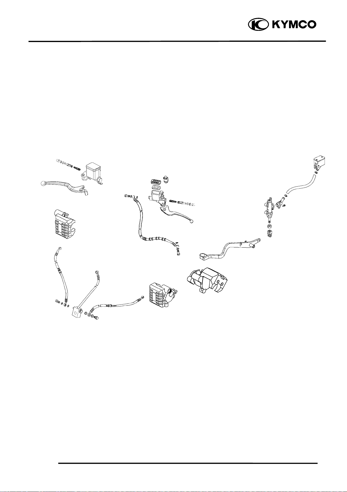
Kymco MO MXU250 Service Manual - chap13 (imp frenante)

13. BRAKE SYSTEM
MXU 250
13
__________________________________________________________________________________
__________________________________________________________________________________
__________________________________________________________________________________
__________________________________________________________________________________
__________________________________________________________________________________
BRAKE SYSTEM
13
__________________________________________________________________________________
SERVICE INFORMATION------------------------------------------------ 13- 2
TROUBLESHOOTING----------------------------------------------------- 13- 2
FRONT HYDRAULIC BRAKE------------------------------------------- 13- 3
FRONT BRAKE FLUID CHANGE/AIR BLEED ---------------------- 13- 4
BR A K E M A S T E R C Y LINDER -------------------------------------------- 13- 6
FRONT BRAKE CALIPER------------------------------------------------ 13- 9
REAR HYDRAULIC BRAKE--------------------------------------------- 13-12
RE A R B R A K E M A S TER C Y L I N D E R ( R E A R BR A K E P E D A L ) ----- 13-15
REAR BRAKE CALIPER-------------------------------------------------- 13-18
13-0
13. BRAKE SYSTEM
MXU 250
13-1
13. BRAKE SYSTEM
m
d
)
)
⎯
)
MXU 250
SERVICE INFORMATION
GENERAL INSTRUCTIONS
• During servicing, keep oil or grease off the brake pads and brake disk.
• Drain the brake fluid from the hydraulic brake system before disassembly.
• Contaminated brake disk or brake pads reduce stopping power. Clean the contaminated brake
disk with high-performance brake degreaser and replace the brake pads.
• Do not use brake fluid for cleaning.
• Bleed air from the brake system if the brake system is removed or the brake is soft.
• Do not allow any foreign matters entering the brake reservoir when filling the brake reservoir
with brake fluid.
• Brake fluid will damage painted, coated surfaces and plastic parts. When working with brake
fluid, use shop towels to cover and protect painted, rubber and plastic parts. Wipe off any splash
of brake fluid with a clean towel. Do not wipe the machine with a towel contaminated by brake
fluid.
• Make sure to use recommended brake fluid. Use of other unspecified brake fluids may cause
brake failure.
• Inspect the brake operation before riding.
SPECIFICATIONS Unit: mm (in)
Ite
Brake disk thickness 3.8~4.2 (0.152~0.168
Brake disk runout
Standar
Service Limit
3 (0.12
0.3 (0.012
TROUBLESHOOTING
Loose brake lever Tight brake lever
• Air in hydraulic brake system •Seized piston
• Brake fluid level too low •Clogged hydraulic brake system
• Hydraulic brake system leakage •Smooth or worn brake pad
Poor brake performance Brake noise
• Air in brake system • Contaminated brake pad surface
• Deteriorated brake fluid • Excessive brake disk run out
• Contaminated brake pads and brake disk • Incorrectly installed caliper
• Worn brake pads • Brake disk or wheel not aligned
• Worn brake master cylinder piston oil seal
• Clogged brake fluid line Hard braking
• Deformed brake disk •Seized hydraulic brake system
• Unevenly worn brake caliper •Seized piston
13-2
13. BRAKE SYSTEM
r
FRONT HYDRAULIC BRAKE
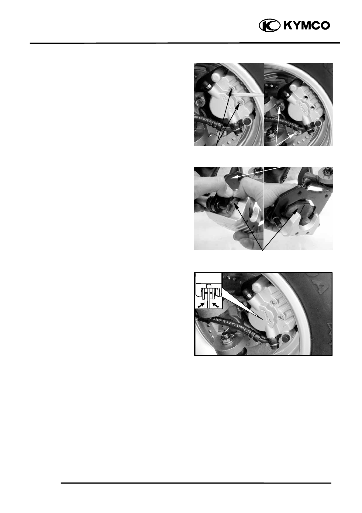
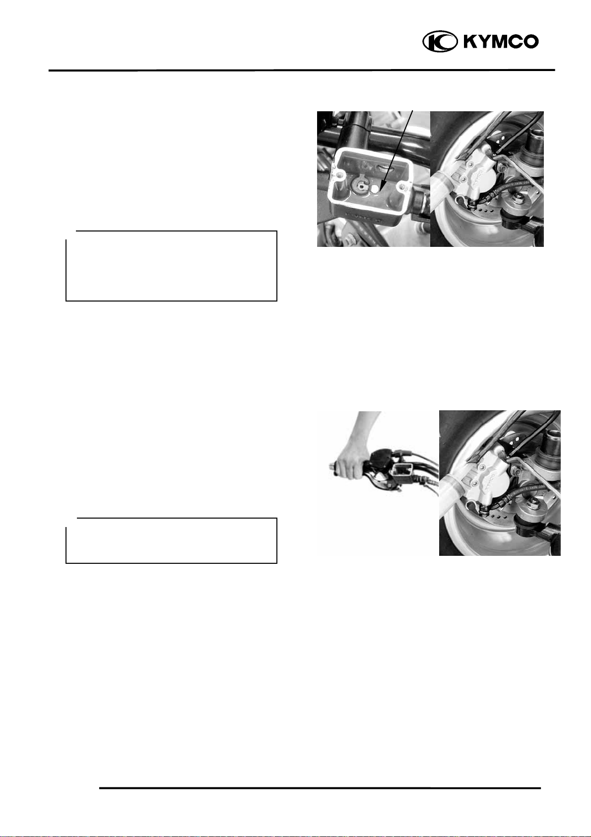
BRAKE PADS REMOVAL
Remove the front wheel. (Öchapter 14)
Remove the two brake pad pins from the
brake caliper.
Remove the two bolts attaching the brake
caliper and then remove brake caliper.
Compress the brake caliper holder and
remove brake pads.
Brake Pad Pins
MXU 250
Bolts
Brake Caliper Holde
A wear indicator is provided on each brake.
The indicators allows checking of brake
pads wear. Check the position of the
indicator.
Brake Pads
13-3
13. BRAKE SYSTEM
BRAKE DISK
Measure the brake disk thickness.
Service Limit: 3 mm (0.12 in)
Measure the brake disk run out.
Service Limit: 0.3 mm (0.012 in)
INSTALLATION
Reverse the “BRAKE PADS REMOVAL”
procedures.
MXU 250
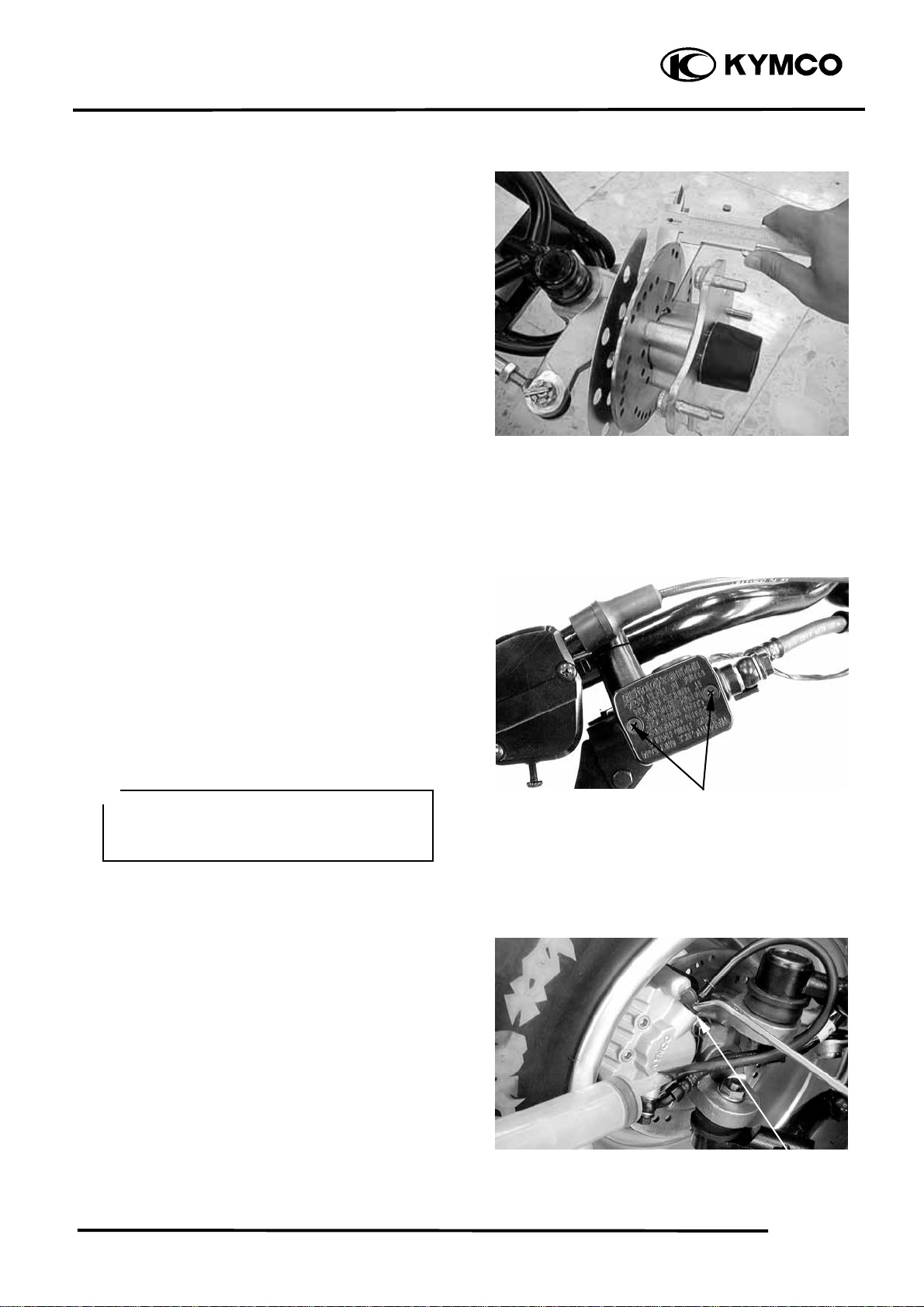
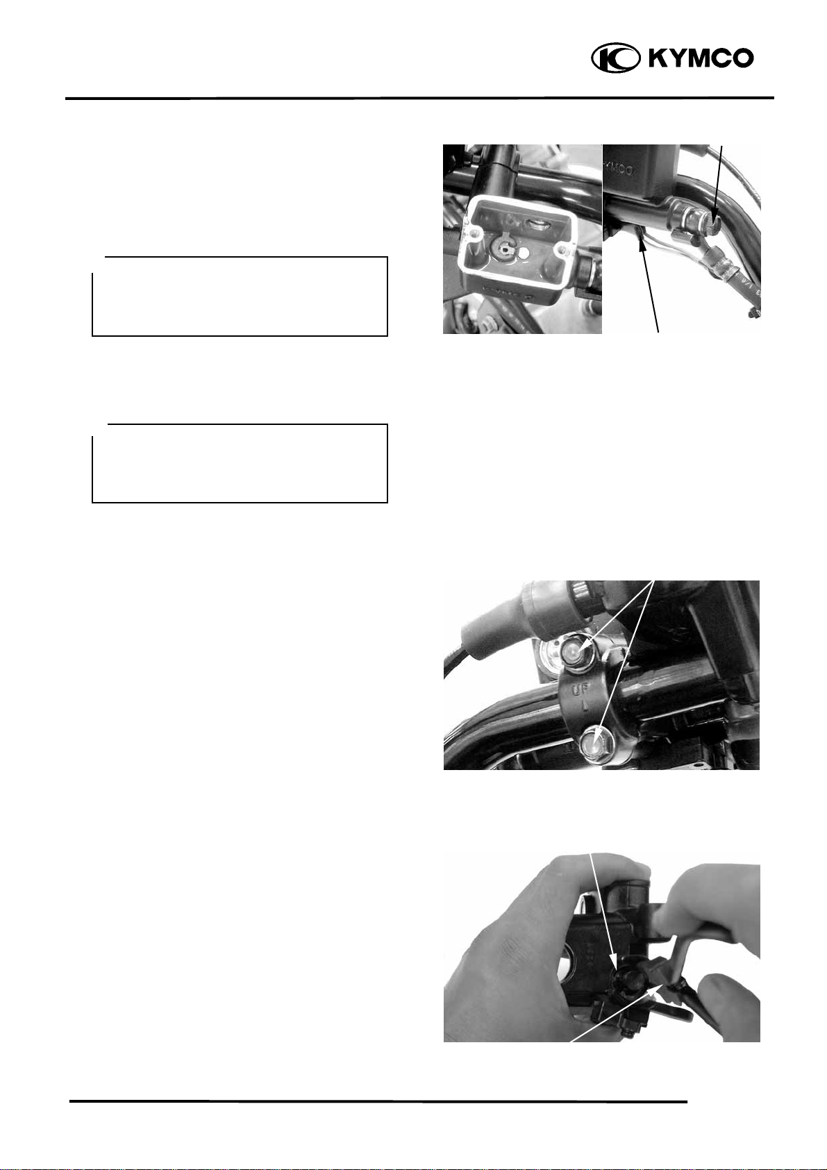
FRONT BRAKE FLUID
CHANGE/AIR BLEED
BRAKE FLUID DRAINING
Place the machine on the level ground and
set the handlebar upright.
Remove the two screws attaching the brake
fluid reservoir cap.
*
Use shop towels to cover plastic parts
and coated surfaces to avoid damage
caused by splash of brake fluid.
Connect a transparent hose to the brake
caliper bleed valve and then loosen the
bleed valve nut.
Use a syringe to draw the brake fluid out
through the hose.
Screws
Bleed Valve
13-4
13. BRAKE SYSTEM
r
MXU 250
BRAKE FLUID REFILLING
Connect a transparent hose and syringe to
the brake caliper bleed valve and then
loosen the bleed valve nut.
Fill the brake reservoir with brake fluid and
use the syringe to draw brake fluid into it
until there is no air bubbles in the hose.
Then, tighten the bleed valve nut.
Torque: 0.6 kgf-m (6 Nm, 4.32 lbf-ft)
*
• When drawing brake fluid with the
syringe, the brake fluid level should be
kept over 1/2 of the brake reservoir
height.
• Use only the recommended brake fluid.
Recommended Brake Fluid: DOT-4
Reservoi
BRAKE SYSTEM BLEEDING
Connect a transparent hose to the bleed
valve and fully apply the brake lever after
continuously pull it several times. Then,
loosen the bleed valve nut to bleed air from
the brake system. Repeat these steps until
the brake system is free of air.
*
When bleeding air from the brake system,
the brake fluid level should be kept over
1/2 of the brake reservoir height.
13-5
13. BRAKE SYSTEM
t
BRAKE MASTER CYLINDER
DISASSEMBLY
Remove the brake reservoir cover
Drain the brake fluid from the hydraulic
brake system. (Ö13-4)
*
Do not splash brake fluid onto any
rubber, plastic and coated parts. When
working with brake fluid, use shop
towels to cover these parts.
Remove fluid tube bolt and then disconnect
the fluid tube.
*
When removing the brake fluid tube bolt,
be sure to place towels under the tube
and plug the tube end to avoid brake
fluid leakage and contamination.
MXU 250
Fluid Tube Bol
Stop Light Switch Wire
Disconnect the stop light switch wires.
Remove the two master cylinder holder
bolts and remove the master cylinder.
Remove the brake lever bolt and the brake
lever.
Remove the piston rubber cover and snap
ring from the brake master cylinder.
Bolts
Snap Ring
Snap Ring Pliers (Close)
13-6
 Loading...