


3. INSPECTION/ADJUSTMENT
MXU 250
3
__________________________________________________________________________________
__________________________________________________________________________________
__________________________________________________________________________________
__________________________________________________________________________________
__________________________________________________________________________________
3
INSPECTION/ADJUSTMENT
__________________________________________________________________________________
SERVICE INFORMATION------------------------------------------------ 3- 1
MAINTENANCE SCHEDULE-------------------------------------------- 3- 2
FUEL LINE/THROTTLE OPERATION/AIR CLEANER ------------ 3- 3
AIR FILTER FOR DRIVE BELT ----------------------------------------- 3- 5
SECONDARY AUR SUPPLY SYSTEM/SPARK PLUG ------------- 3- 6
VALVE CLEARANCE----------------------------------------------------- 3- 7
CARBURETOR IDLE SPEED/IGNITION TIMING ------------------ 3- 8
CYLINDER COMPRESSION/ ENGINE OIL--------------------------- 3- 9
TRANSMISSION OIL REPLACEMENT ------------------------------- 3-11
DRIVE BELT/BRAKE PADS INSPECTION--------------------------- 3-12
BRAKE FLUID INSPECTION/ HEADLIGHT AIM------------------- 3-13
STEERING SYSTEM INSPECTION------------------------------------- 3-14
TOE-IN ADJUSTMENT --------------------------------------------------- 3-15
WHEELS/TIRES ------------------------------------------------------------ 3-16
DRIVE CHAIN SLACK ADJUSTMENT-------------------------------- 3-18
DRIVE SELECT LEVER ADJUSTMENT ------------------------------ 3-20
CABLE INSPECTION AND LUBRICATION-------------------------- 3-21
REAR SUSPENSION LUBRICATION---------------------------------- 3-21
COOLING SYSTEM-------------------------------------------------------- 3-22
SPARK ARRESTER CLEANING (OFF ROAD)----------------------- 3-23
3-0
3. INSPECTION/ADJUSTMENT
MXU 250
SERVICE INFORMATION
GENERAL
! WARNING
•Before running the engine, make sure that the working area is well-ventilated. Never run the
engine in a closed area. The exhaust contains poisonous carbon monoxide gas which may
cause death to people.
•Gasoline is extremely flammable and is explosive under some conditions. The working area
must be well-ventilated and do not smoke or allow flames or sparks near the working area or
fuel storage area.
SPECIFICATIONS
ENGINE
Throttle grip free play : 1~4 mm (0.04~0.16 in)
Spark plug gap : 0.6~0.7 mm (0.002~0.003 in)
Spark plug: Standard : DPR7EA-9
Valve clearance : IN: 0.1 mm (0.004 in)
EX: 0.1 mm (0.004 in)
Idle speed : 1500±100 rpm
Engine oil capacity:
At disassembly : 1.6 liter (1.4 lmp qt, 1.7 Us qt)
At change : 1.4 liter (1.23 lmp qt, 1.48 Us qt)
Gear oil capacity :
At disassembly : 400 cc (0.35 lmp qt, 0.42 Us qt)
At change : 300 cc (0.26 lmp qt, 0.32 Us qt)
Cylinder compression : 15±2 kg/cm²
Ignition timing : BTDC 5°±1°/2000 rpm
TIRE PRESSURE
Front 0.28 kgf/cm² (28 Kpa, 3.2 psi)
Rear 0.28 kgf/cm² (28 Kpa, 3.2 psi)
TIRE SIZE:
Front : 22*7-10
Rear : 22*10-10
TORQUE VALUES
Front wheel nut 4.5 kgf-m (45 Nm, 32 lbf-ft)
Rear wheel nut 4.5 kgf-m (45Nm, 32 lbf-ft)
3-1
1 Rider
3. INSPECTION/ADJUSTMENT
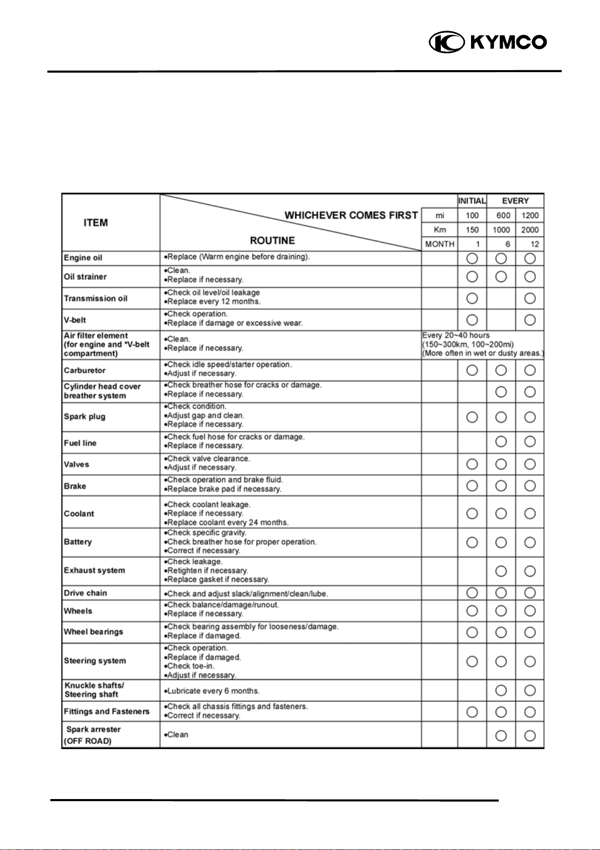
MAINTENANCE SCHEDULE
This chapter includes all information necessary to perform recommended inspections and
adjustments. These preventive maintenance procedures, if followed, will ensure more reliable
vehicle operation and a longer service life. The need for costly overhaul work will be greatly
reduced. This information applies to vehicles already in service ad well as new vehicles that are
being prepared for sale. All service technicians should be familiar with this entire chapter.
MXU 250
•In the interest of safety, we recommend these items should be serviced only by an authorized
KYMCO motorcycle dealer.
3-2
3. INSPECTION/ADJUSTMENT
r
t
r
FUEL LINE
Check the fuel tubes and replace any parts,
which show signs of deterioration, damage
or leakage.
*
Do not smoke or allow flames or sparks
in your working area.
MXU 250
Fuel Filte
Fuel tubes
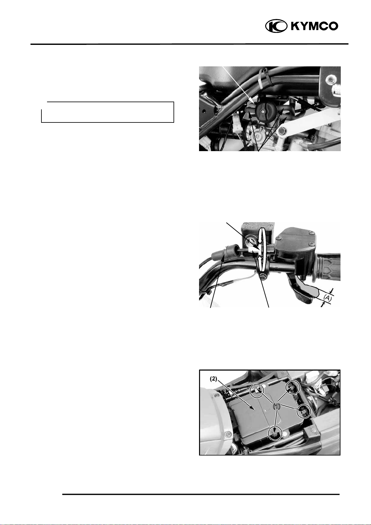
THROTTLE OPERATION
Check the throttle to swing for smooth
movement.
Measure the throttle to swing free play.
Free Play (A): 1~4 mm (0.04~0.16 in)
To adjust throttle free play:
Slide the rubber sleeve back to expose the
throttle cable adjuster.
Loosen the lock nut, then turn the adjuster
to obtain the correct free play. (1~4 mm or
0.04~0.16 in)
Tighten the lock nut and reinstall the sleeve.
AIR CLEANER
AIR CLEANER REPLACEMENT
Remove the seat. (See page 2-3)
Unlatch the four retainer clips (1) and
remove the air cleaner housing cover (2).
Lock nu
Rubber sleeve
Cable adjuste
3-3
3. INSPECTION/ADJUSTMENT
r
r
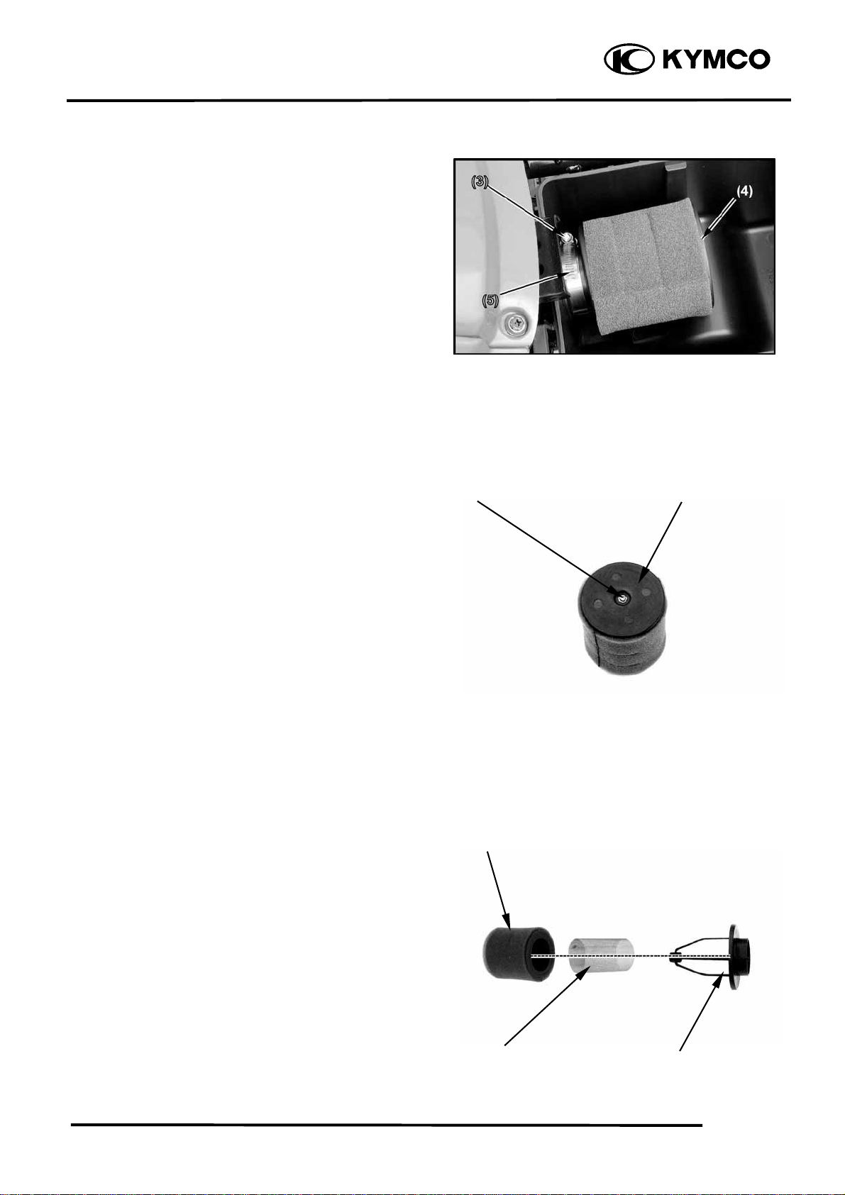
Unscrew (3) the clamp (5) and remove the
air cleaner assembly (4) from the air cleaner
housing.
MXU 250
Remove the screw and remove the air
cleaner assembly from the air cleaner
holder.
Remove the air cleaner and air cleaner
screen from the air cleaner body.
Remove the air cleaner net from the air
cleaner.
Screw Air Cleaner Holde
Air Cleane
Reassemble by reversing the disassembly
sequence.
Air Cleaner screen
Air Cleaner body
3-4
3. INSPECTION/ADJUSTMENT
r
m
r
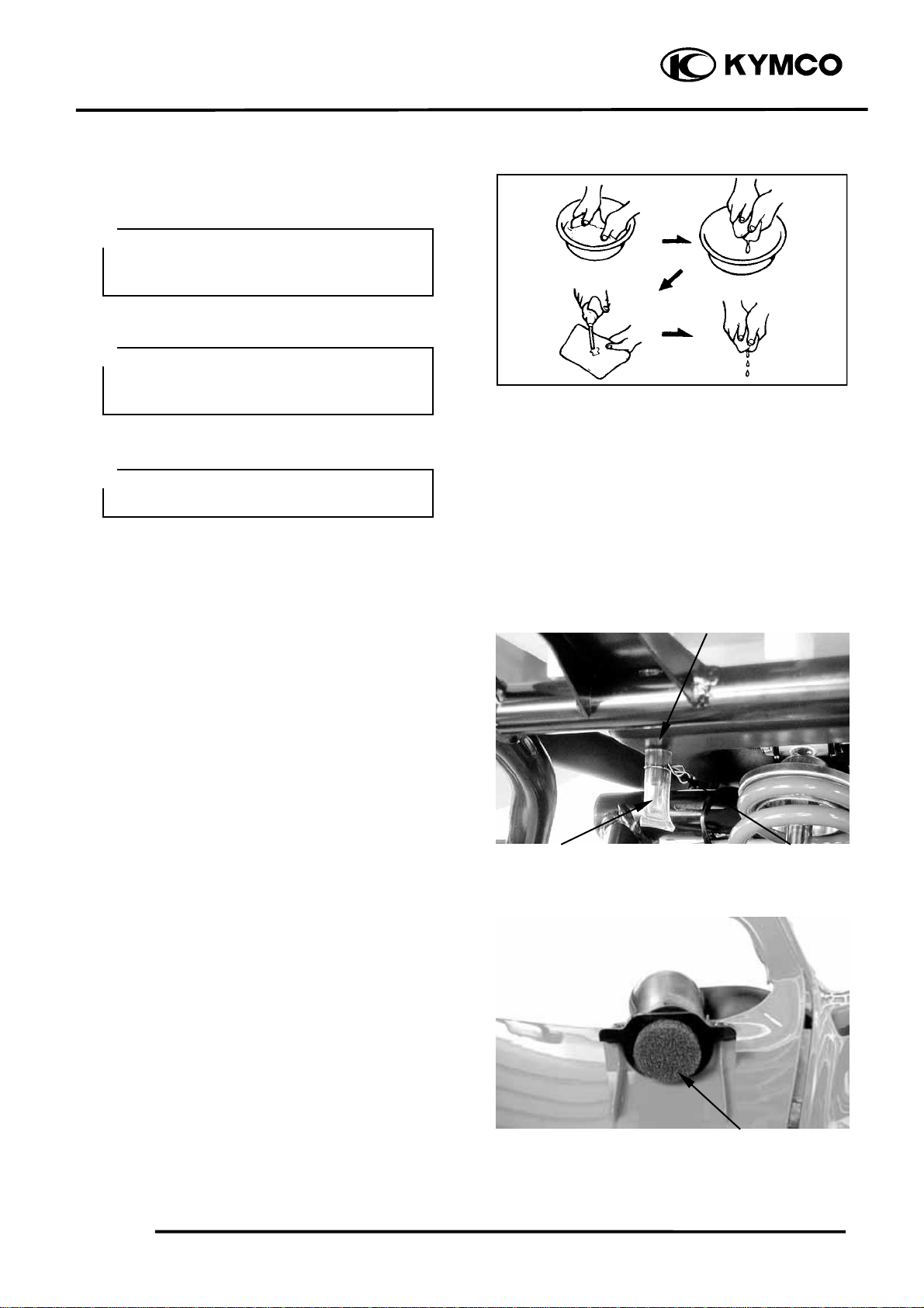
CLEAN AIR FILTER ELEMENT
Wash the element gently, but throughly in
solvent.
*
Use parts cleaning solvent only. Neve
use gasoline or low flash point solvents
which may lead to a fire or explosion.
Squeeze the excess solvent out of the
element and let dry.
*
Do not twist or wring out the foa
element. This could damage the foam
material.
Apply the engine oil.
Squeeze out the excess oil.
*
The element should be wet but not
dripping.
More frequent replacement is required when
riding in unusually dusty or rainy areas.
MXU 250
AIR CLEANER HOUSING DRAIN
Remove the drain tube (under air cleaner
case) by removing the clip.
Drain the deposits.
Reinstall the drain tube, securing it with the
clip.
AIR FILTER FOR DRIVE BELT
To clean the air filter:
Remove front center cover. (See page 2-7)
Remove air filter.
Tap the element lightly to remove most of
the dust and dirt.
Blow out the remaining dirt with
compressed air.
Drain Tube
Air Cleaner Housing
Clip
Installation is in the reverse order of
removal.
If necessary replace the air filter.
3-5
Air Filte
3. INSPECTION/ADJUSTMENT
MXU 250
SECONDARY AIR SUPPLY
SYSTEM
This model is equipped with a built-in
secondary air supply system. The pulse
secondary air supply system is located on
the cylinder head cover.
The secondary air supply system introduces
filtered air into exhaust gases in the exhaust
port. The secondary air is drawn into the
exhaust port whenever there is negative
pressure pulse in the exhaust system. This
charged secondary air promotes burning of
the unburned exhaust gases and changes a
considerable amount of hydrocarbons and
carbon monoxide into relatively harmless
carbon dioxide and water.
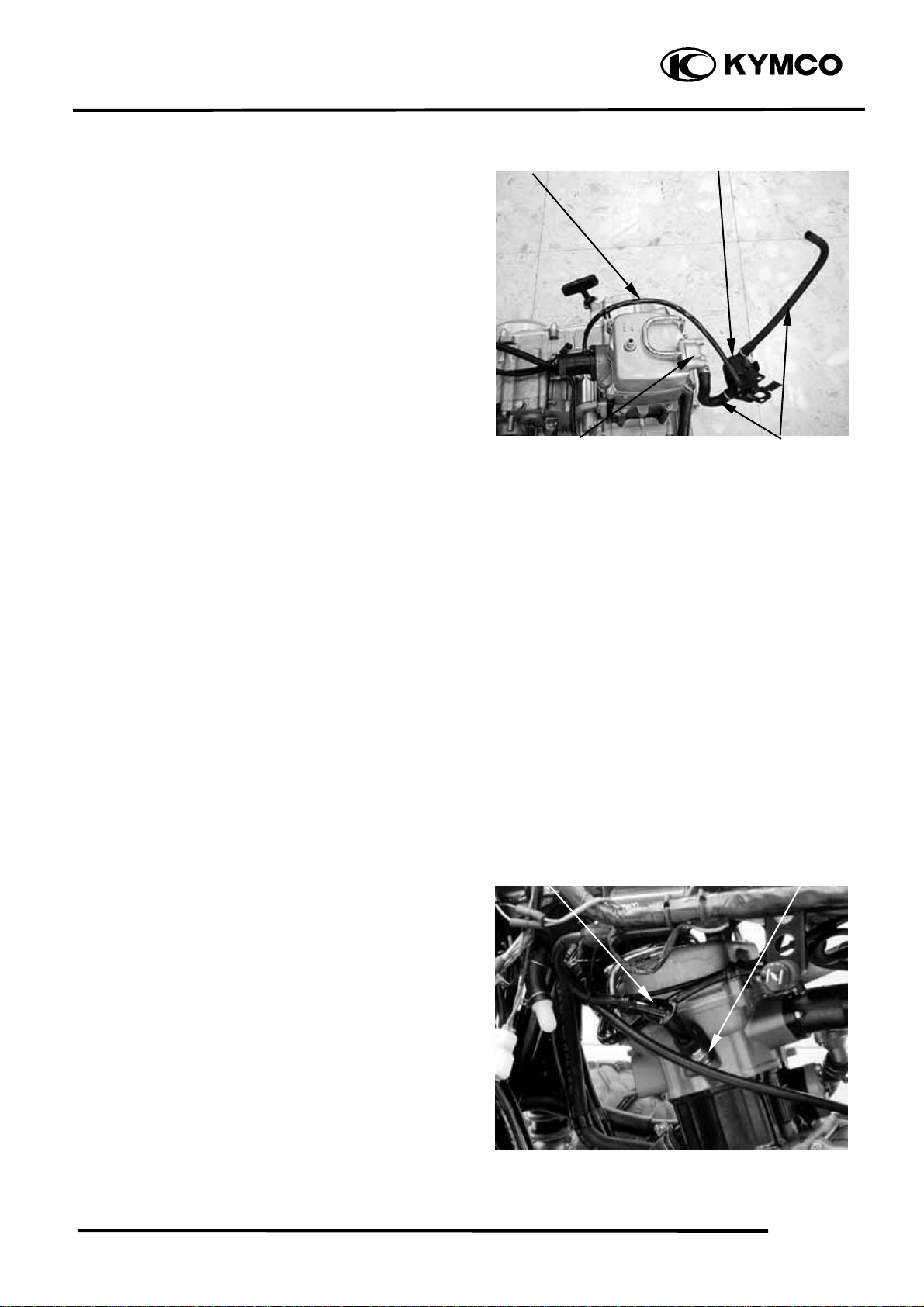
Check the PAIR (pulse secondary air
injection) hoses between the PAIR control
solenoid valve and cylinder head cover for
deterioration, damage or loose connections.
Make sure the hoses are not cracked.
If the hoses show any signs of heat damage,
inspect the PAIR check valve in the PAIR
reed valve cover damage.
Vacuum Hose
PAIR Control solenoid Valve
Air Supply HosePAIR Check Valve
SPARK PLUG
Remove ignition coil cap and spark plug.
Check the spark plug for wear and fouling
deposits.
Clean any fouling deposits with a spark
plug cleaner or a wire brush.
Specified Spark Plug: DPR7EA-9
Ignition Coil Cap
Spark Plug
3-6
3. INSPECTION/ADJUSTMENT
k
r
MXU 250
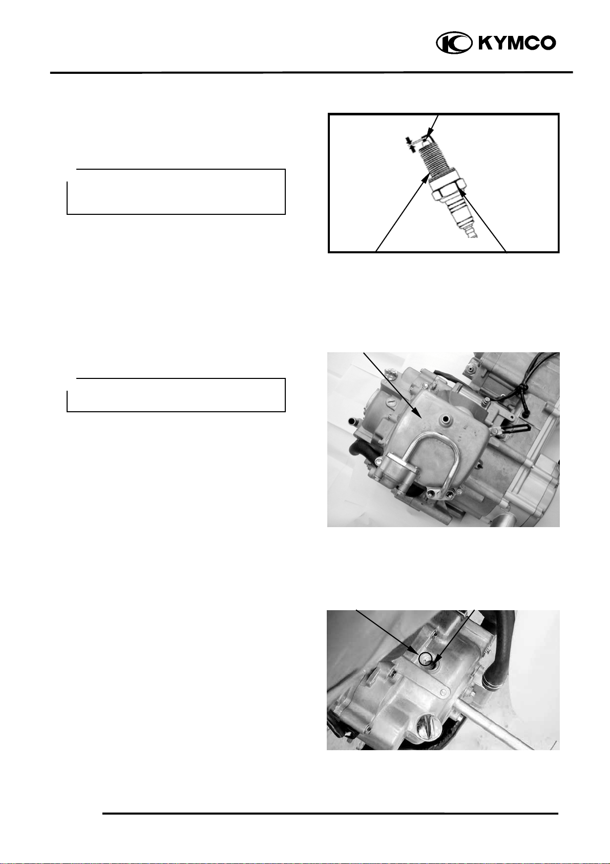
Measure the spark plug gap.
Spark Plug Gap: 0.6~0.7 mm (0.002~
0.003 in)
*
When installing, first screw in the spar
plug by hand and then tighten it with a
spark plug wrench.
VALVE CLEARANCE
*
Inspect and adjust valve clearance while
the engine is cold (below 35℃).
Gap, Wear, and Fouling Deposits
Washer Deformation
Cylinder Head Cove
Cracks, Damage
Remove the cylinder head cover. (See
chapter 7)
Turn the flywheel clockwise so that the “T”
mark on the flywheel aligns with the index
mark on the right crankcase cover to bring
the round hole on the camshaft gear facing
up to the top dead center on the
compression stroke.
Inspect and adjust the valve clearance.
Valve Clearance: IN: 0.1 mm (0.004 in)
EX: 0.1 mm (0.004 in)
“T” MarkIndex Mark
3-7

3. INSPECTION/ADJUSTMENT
r
MXU 250
Loosen the lock nut and adjust by turning
the adjusting nut
Special
Tappet adjuster E012
*
• Check the valve clearance again afte
the lock nut is tightened.
CARBURETOR IDLE SPEED
*
• The engine must be warm for accurate
idle speed inspection and adjustment.
Valve Wrench
Round Hole
Warm up the engine before this operation.
Start the engine and connect a tachometer.
Turn the throttle stop screw to obtain the
specified idle speed.
Idle Speed: 1500±100 rpm
When the engine misses or run erratic,
adjust the air screw.
IGNITION TIMING
*
The ignition unit is not adjustable. If the
ignition timing is incorrect, check the
ignition system.
Remove the timing hole cap.
Check the ignition timing with a timing
light.
When the engine is running at idle speed,
the ignition timing is correct if the “F” mark
on the flywheel aligns with the index mark
on the right crankcase cover.
AirScrew
Timing Hole Cap
Throttle Stop Screw
Index Mark
Timing Hole
3-8

3. INSPECTION/ADJUSTMENT
CYLINDER COMPRESSION
Warm up the engine before compression
test.
Remove the spark plug.
Insert a compression gauge.
Open the throttle valve fully and push the
starter button to test the compression.
Compression: 15±2 kg/cm
If the compression is low, check for the
following:
- Leaky valves
- Valve clearance too small
- Leaking cylinder head gasket
- Worn piston rings
- Worn piston/cylinder
If the compression is high, it indicates that
carbon deposits have accumulated on the
combustion chamber and the piston head.
2
MXU 250
Compression Gauge
ENGINE OIL
OIL LEVEL
Place the machine on a level place.
Warm up the engine for several minutes and
stop it.
*
Run the engine for 2~3 minutes and
check the oil level after the engine is
stopped for 2~3 minutes.
Check the oil level through the inspection
window.
The oil level should be between the
maximum (H) and minimum (L) marks. If
the level is low, add oil to raise it to the
proper level.
Inspection Window
Upper Level
Lower Level
3-9

3. INSPECTION/ADJUSTMENT
g
p
ENGINE OIL REPLACEMENT
Place the machine on a level place.
Warm up the engine for several minutes and
stop it.
Place a container under the engine.
Remove the oil fill cap and drain plug to
drain the oil.
Reinstall the drain plug and tighten the
drain plug to specification.
Torque: 2.5 kgf-m (25 Nm, 15 lbf-ft)
MXU 250
Oil Fill Cap
Fill the engine with oil and install the oil fill
cap.
*
The engine oil will drain more easily
while the engine is warm.
Oil Capacity:
At disassembly: 1.6 liter (1.4 lmp qt,
1.7 Us qt)
At change: 1.4 liter (1.23 lmp qt, 1.48 Us
qt)
ENGINE OIL REPLACEMENT AND
OIL FILTER CLEANING
Place the machine on a level place.
Warm up the engine for several minutes and
stop it.
Place a container under the engine.
Remove the oil fill cap and oil filter cap to
drain the oil.
Drain Plu
Oil Filter Ca
3-10

3. INSPECTION/ADJUSTMENT
r
p
t
MXU 250
Clean the oil strainer with solvent.
Inspect the O-ring and replace if damaged.
Reinstall the O-ring, oil strainer,
compression spring and oil filter cap.
Tighten the oil filter cap to specification.
Torque: 1.5 kgf-m (15 Nm, 11 lbf-ft)
Fill the engine with oil and install the oil fill
cap.
Oil Capacity:
At disassembly: 1.6 liter (1.4 lmp qt,
1.7 Us qt)
At change: 1.4 liter (1.23 lmp qt, 1.48 Us
qt)
TRANSMISSION OIL
REPLACEMENT
Place the machine on a level place.
Place a container under the engine.
Remove the oil filler bolt and drain plug to
drain the oil.
Reinstall the drain plug and tighten to
specification.
Torque: 2.5 kgf-m (25 Nm, 18 lbf-ft)
Compression Spring
Oil Straine
Oil Filler Bol
O-ring
Oil Filter Ca
Fill the engine with oil and install the oil
filler bolt.
Oil Capacity:
At disassembly : 400 cc (0.35 lmp qt,
0.42 Us qt)
At change : 300 cc (0.26 lmp qt,
0.32 Us qt)
Start the engine and warm up for a few
minutes. While warming up, check for oil
leakage. If oil leakage is found, stop the
engine immediately and check for the cause.
*
Make sure that the sealing washer is in
good condition.
3-11
Drain Plug

3. INSPECTION/ADJUSTMENT
t
r
r
DRIVE BELT
Remove the left crankcase cover.
Inspect the drive belt for cracks, scaling,
chipping or excessive wear.
Measure the V-belt width
Service limit: 22 mm (0.88in)
Replace the drive belt if out of specification.
BRAKE PADS INSPECTION
A wear indicator is provided on each brake.
The indicators allows checking of brake
pads wear. Check the position of the
indicator. If the indicator reaches the wear
limit line, to replace the pads.
MXU 250
Drive Bel
Front Calipe
Rear Calipe
3-12

3. INSPECTION/ADJUSTMENT
MXU 250
BRAKE FLUID INSPECTION
Check if the fluid level is below the lower
level mark through the inspection window.
Inspection Window (R/L Brake Lever)
Inspection Window (Rear Brake Pedal)
HEADLIGHT AIM
Turn the ignition switch ON and start the
engine.
Turn on the headlight switch.
Adjust the headlight aim by turning the
headlight aim adjusting screw.
3-13
Adjust Screw

3. INSPECTION/ADJUSTMENT
STEERING SYSTEM
INSPECTION
Place the machine on a level place.
Check the steering column bushings and
bearings:
Move the handlebar up and down, and/or
back and forth.
Replace the steering column bushings and
or bearings if excessive play
MXU 250
Check the tie-rod ends
Turn the handlebar to the left and/or right
until it stops completely, then slightly move
the handlebar from left to right.
Replace the tie-rod ends if tie-rod end has
any vertical play.
Raise the front end of the machine so that
there is no weight on the front wheels.
Check ball joints and/or wheel bearings.
Move the wheels lately back and froth.
Replace the front arms and/or wheel
bearings if excessive free play.
Tie-rod Ends
3-14

3. INSPECTION/ADJUSTMENT
MXU 250
TOE-IN ADJUSTMENT
Place the machine on a level place.
Measure the toe-in
Adjust if out of specification.
Toe-in measurement steps:
Mark both front tire tread centers.
Raise the front end of the machine so that
there is no weight on the front tires.
Fix the handlebar straight ahead.
Measure the width A between the marks.
Rotate the front tires 180 degrees until the
marks come exactly opposite.
Measure the width B between the marks.
Calculate the toe-in using the formula given
below.
Toe-in = B-A
Toe-in: 0~15 mm (0~0.6 in)
If the toe-in is incorrect, adjust the toe-in
A
B
Adjust the toe-in step:
Mark both tie-rods ends.
This reference point will be needed during
adjustment.
Loosen the lock nuts (tie-rod end) of both
tie-rods
The same number of turns should be given
to both tie-rods right and left until the
specified toe-in is obtained, so that the
lengths of the rods will be kept the same.
Tighten the rod end locknuts of both tierods
Torque: 3 kgf-m (30 Nm, 22 lbf-ft)
3-15
Tie-rod
Tie-rod End Nuts

3. INSPECTION/ADJUSTMENT
t
MXU 250
*
• Be sure that both tie-rod are turned the
same amount. If not, the machine will
drift tight or left even though the
handlebar is positioned straight which
may lead to mishandling and accident.
• After setting the toe-in to specification,
run the machine slowly for some
distance with hands placed lightly on
the handlebar and check that the
handlebar responds correctly. If not,
turn either the right or left tie-rod
within the toe-in specification.
WHEELS/TIRES
Check the tires for cuts, imbedded nails or
other damages.
Check the tire pressure.
*
Tire pressure should be checked when
tires are cold.
Tie-rod End Nuts
Tie-rod
TIRE PRESSURE
1 Rider
Front 0.28 kgf/cm² (28 Kpa, 3.2 psi)
Rear 0.28 kgf/cm² (28 Kpa, 3.2 psi)
TIRE SIZE
Front: 22*7-10
Rear : 22*10-10
Check the front axle nut for looseness.
Front Axle Nu
3-16

3. INSPECTION/ADJUSTMENT
t
MXU 250
Check the rear axle nut for looseness.
If the axle nuts are loose, tighten them to the
specified torque.
Torque:
Front : 7 kgf-m (70 Nm, 50 lbf-ft)
Rear : 10 kgf-m (100 Nm, 72 lbf-ft)
RearAxle Nu
Inspect the tire surfaces.
Replace if wear or damage.
Tire wear limit: 3 mm (0.12 in)
*
It is dangerous to ride with a worn out
tire. When a tire wear is out of
specification, replace the tire
immediately.
WHEEL INSPECTION
Inspect the wheel.
Replace if damage or bends
Always balance the wheel when a tire or
wheel has been changed or replaced.
*
• Never attempt even small repairs to the
wheel.
• Ride conservatively after installing a
tire to allow it to seat itself properly on
the rim.
3-17

3. INSPECTION/ADJUSTMENT
t
t
DRIVE CHAIN SLACK
ADJUSTMENT
Before checking and/or adjusting, rotate the
rear wheels several revolutions and check
slack at several points to find the tightest
point. Check and/or adjust the chain slack
with the rear wheels in this “tightest”
position.
*
Too little of chain slack will overload the
engine and other vital parts; keep the
Place the machine on a level place.
*
Wheels should be on the ground without
Check drive chain slack.
Adjust if out of specification.
Drive chain slack (A):
30 ~ 40 mm (1.2 ~ 1.6 in)
MXU 250
Adjust drive chain slack:
Loosen the caliper holder bolt and two axle
hub holding bolt.
Provide a proper pin and pass the pin
through the axle hub and driven sprocket.
Bol
Bolts
Driven Sprocke
Pin
Axle Hub
3-18

3. INSPECTION/ADJUSTMENT
t
To tighten the chain, push the ATV
forward.
To loosen the chain, pull the ATV
backward.
MXU 250
Retighten the two axle hub holder bolt and
caliper holder bolt to the specification.
Torque:
Axle hub holding bolt:
4 kgf-m (40 Nm, 29 lbf-ft)
Caliper holder bolt:
1 kgf-m (10 Nm, 7.2 lbf-ft)
Pull out the pin.
Bolts
Bol
Pin
3-19

3. INSPECTION/ADJUSTMENT
r
m
r
MXU 250
DRIVE SELECT LEVER
ADJUSTMENT
Turn the ignition switch is ON and make
sure the engine stop switch in the OFF
position.
Loosen the lock nuts of rod.
Shift the gear to neutral by moving the shift
lever and/or turn the rod. (The neutral
indicator lamp comes on.)
Provide standard/phillips screwdriver and
pass the standard/phillips screwdriver
through the shift arm into the index hole at
the transmission case cover.
Turn the rod clockwise or counterclockwise
until the drive select lever into the "N"
position of the shift guide and tighten the
lock nuts, then pull out the standard/phillips
screwdriver.
After adjustment, start the engine and test to
ride the ATV to be sure the drive select
lever is operating properly.
Rod
Standard/Phillips Screwdrive
Lock Nuts
Shift Ar
Drive Leve
Index Hole
Rod
3-20

3. INSPECTION/ADJUSTMENT
N
CABLE INSPECTION AND
LUBRICATION
*
Damaged cable sheath may cause
corrosion and interfere with the cable
movement. An unsafe condition may
result so replace such cable as soon as
possible.
Inspect the cable sheath.
Replace if damage.
Check the cable operation.
Lubricate or replace if unsmooth operation.
*
Hold cable end high and apply several
drops of lubricant to cable.
MXU 250
LEVER LUBRICATION
Lubricate the pivoting parts of each lever.
REAR SUSPENSION
LUBRICATION
Inject grease into the nipples using a grease
gun until slight over flow is observed from
the thrust covers.
*
Wipe off the excess grease.
ipple
3-21

3. INSPECTION/ADJUSTMENT
t
MXU 250
COOLING SYSTEM
COOLANT LEVEL INSPECTION
Place the machine on the level ground.
Check the coolant level in the coolant
reservoir when the engine is cold as the
coolant level will vary with engine
temperature. The coolant level should be
between the maximum and minimum marks.
If the level is low, remove the coolant
reservoir cap, and then add coolant or
distilled water to raise it to the specified
level.
Recommended Coolant: SIGMA Coolant
(Standard Concentration 30%)
*
The coolant level does not change no
matter the engine is warm or cold. Fill to
the maximum mark.
COOLANT REPLACEMENT
*
Perform this operation when the engine
is cold.
Maximum Mark
Coolant Reservoir Cap
Minimum Mark
Remove the front fender. (Ö2-8)
Remove the radiator cap.
Remove the drain bolt to drain the coolant.
Drain the coolant in the reserve tank.
Reinstall the drain bolt.
*
The coolant freezing point should be 5
°C lower than the temperature of the
riding area.
Coolant capacity:
1400 cc (1232 lmp qt, 1484 Us qt)
Radiator capacity:
1100 cc (968 lmp qt, 1166 Us qt)
Reserve tank capacity:
300 cc (264 lmp qt, 318 Us qt)
Start the engine and check if there are no
bubbles in the coolant and the coolant level
is stable. Reinstall the radiator cap.
If there are bubbles in the coolant, bleed air
from the system.
Fill the reserve tank with the recommended
coolant up to the maximum mark.
Drain Bol
3-22
3. INSPECTION/ADJUSTMENT
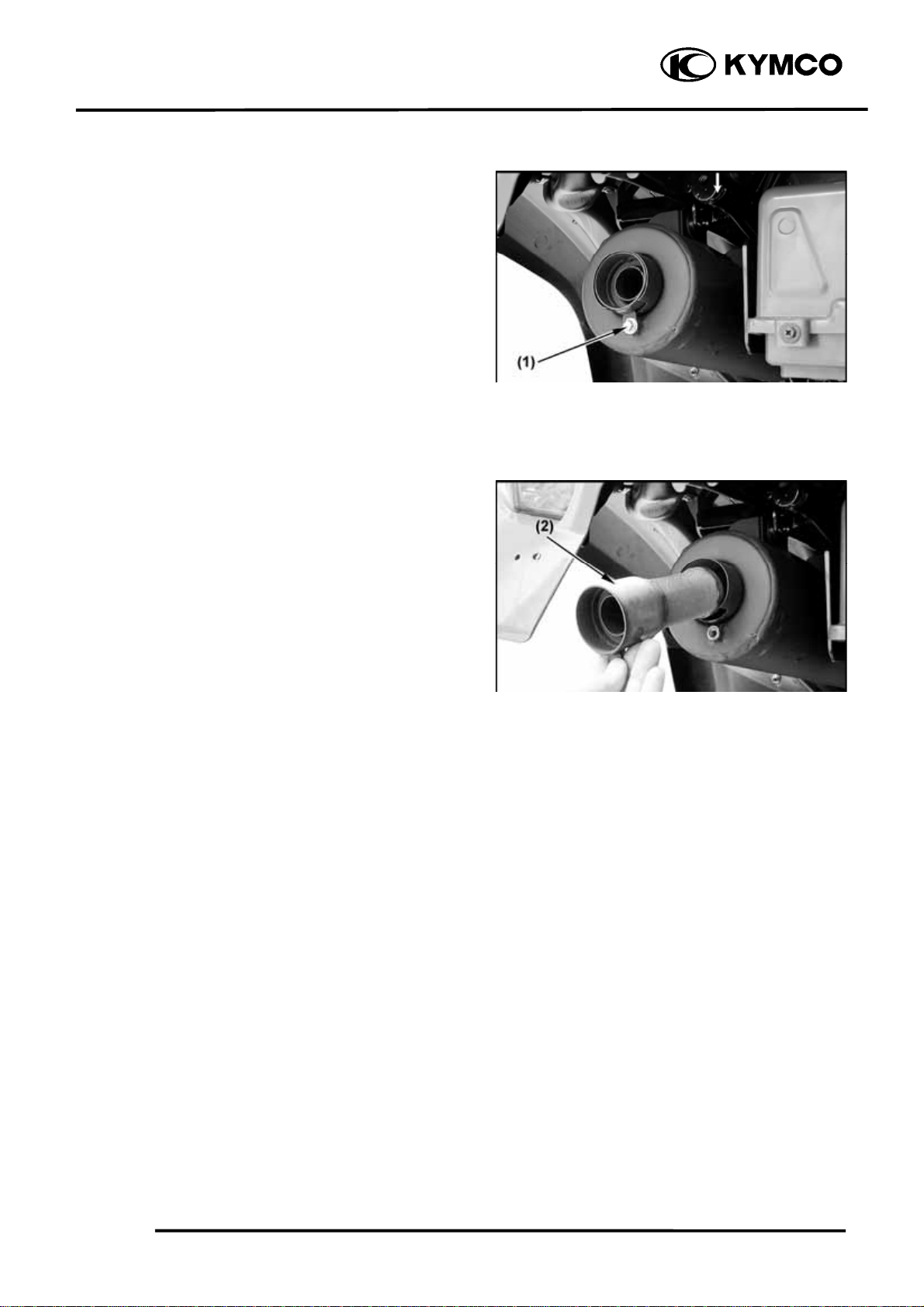
SPARK ARRESTER CLEANING
(OFF ROAD)
Be sure the exhaust pipe and muffler are
cool before cleaning the spark arrester.
1. Remove the bolt (1).
2. Remove the tailpipe (2) by pulling it out
of the muffler.
3. Tap the tailpipe lightly, then use a wire
brush to remove any carbon deposits
from the spark arrester portion of the
tailpipe.
4. Insert the tailpipe into the muffler and
align the screw holes.
5. Install the bolt and tighten it.
MXU 250
3-23
 Loading...