

Kymco MO MXU250 Service Manual - chap05 (imp alimentazione)

5. FUEL SYSTEM
MXU 250
5
__________________________________________________________________________________
__________________________________________________________________________________
__________________________________________________________________________________
__________________________________________________________________________________
__________________________________________________________________________________
5
FUEL SYSTEM
__________________________________________________________________________________
SERVICE INFORMATION------------------------------------------------ 5- 2
TROUBLESHOOTING----------------------------------------------------- 5- 3
FUEL TANK ----------------------------------------------------------------- 5- 4
FUEL VALVE --------------------------------------------------------------- 5- 4
THROTTLE VALVE---------------------------------------------------------- 5- 7
CARBURETOR-------------------------------------------------------------- 5- 9
AIR CLEANER HOUSING------------------------------------------------ 5-15
PAIR SOLENOID VALVE ------------------------------------------------ 5-16
5-0
5. FUEL SYSTEM
MXU 250
5-1
5. FUEL SYSTEM
MXU 250
SERVICE INFORMATION
GENERAL INSTRUCTIONS
Gasoline is very dangerous. When working with gasoline, keep sparks and flames away
from the working area.
Gasoline is extremely flammable and is explosive under certain conditions. Be sure to
work in a well-ventilated area.
• Do not bend or twist control cables. Damaged control cables will not operate smoothly.
• When disassembling fuel system parts, note the locations of O-rings. Replace them with new
ones during reassembly.
• Before float chamber disassembly, loosen the drain screw to drain the residual gasoline into a
clean container.
• After the carburetor is removed, plug the intake manifold side with a clean shop towel to prevent
foreign matters from entering.
• When cleaning the carburetor air and fuel jets, the O-rings and diaphragm must be removed first
to avoid damage. Then, clean with compressed air.
• When the motorcycle is not used for over one month, drain the residual gasoline from the float
chamber to avoid erratic idling and clogged slow jet due to deteriorated fuel.
SPECIFICATIONS
Item Standard
Type PTG
Venturi dia. φ22
Float level 14.8mm
Main jet No. 98
Adjust method Piston
Idle speed 1500±100rpm
Throttle grip free play 1~4mm
Air screw opening 11/8±1/2
5-2

5. FUEL SYSTEM
SPECIAL TOOL
Float level gauge
MXU 250
TROUBLESHOOTING
Engine cranks but won’t start Engine lacks power
• No fuel in tank • Clogged air cleaner
• No fuel to carburetor • Faulty carburetor
• Cylinder flooded with fuel • Faulty ignition system
• No spark at plug
• Clogged air cleaner Lean mixture
• Intake air leak • Clogged carburetor fuel jets
• Improper throttle operation • Float level too low
• Intake air leak
Engine idles roughly, stalls or runs poorly • Clogged fuel tank cap breather hole
• Excessively used choke • Kinked or restricted fuel line
• Ignition malfunction
• Faulty carburetor Rich mixture
• Poor quality fuel • Float level too high
• Lean or rich mixture • Clogged air jets
• Incorrect idle speed • Clogged air cleaner
Misfiring during acceleration
• Faulty ignition system
• Faulty carburetor
Backfiring at deceleration
• Float level too low
• Incorrectly adjusted carburetor
• Faulty exhaust muffler
5-3
5. FUEL SYSTEM
g
N
MXU 250
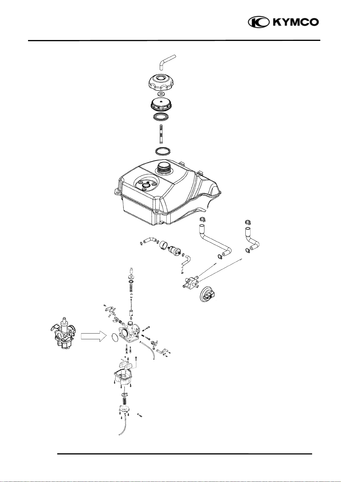
FUEL TANK
REMOVAL
Warnin
• Keep sparks and flames away from the
work area.
• Wipe off any spilled gasoline.
Remove the seat (See page 2-3), right and
left side frame cover (See page 2-6) and fuel
tank cover (See page 2-5).
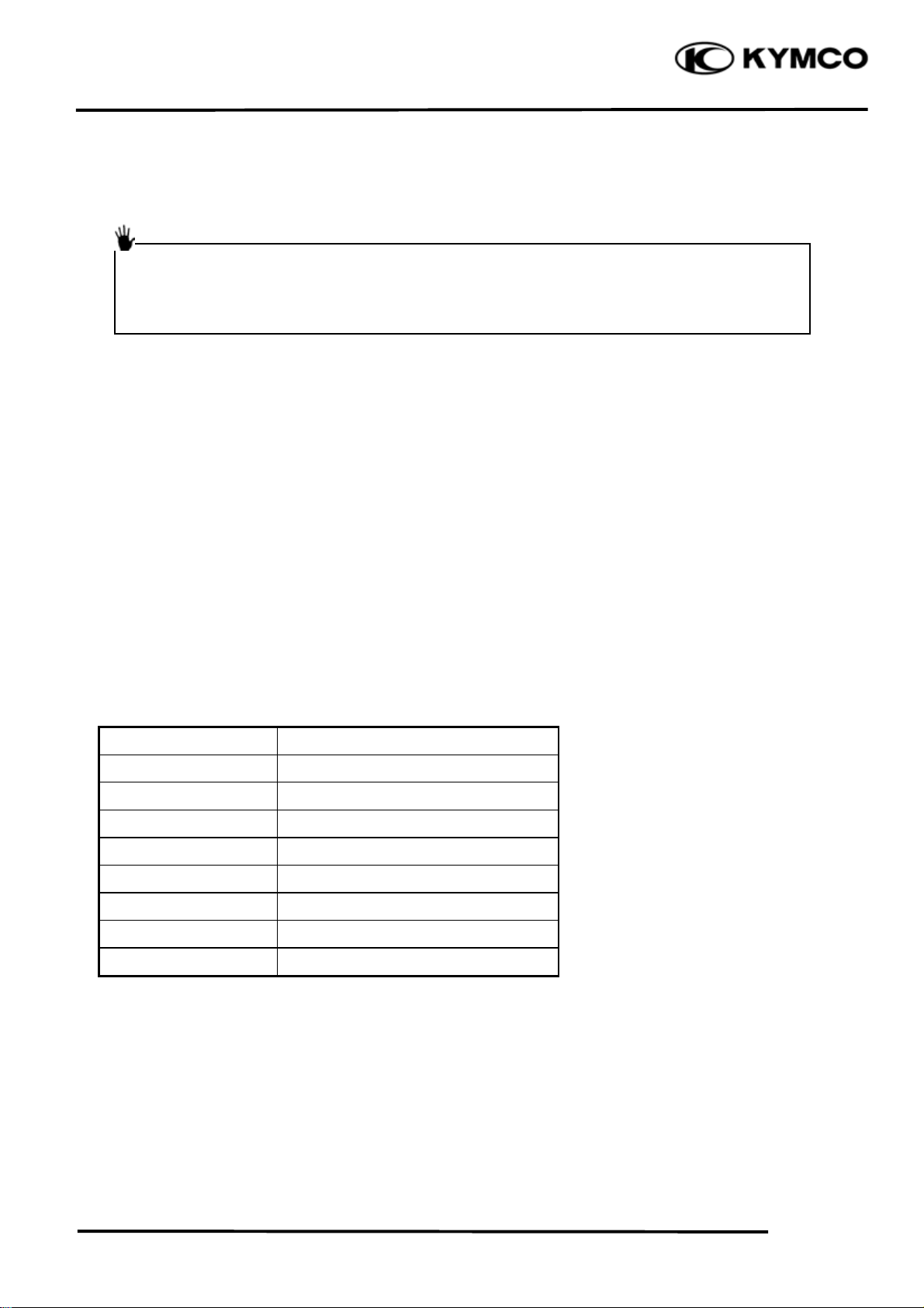
Switch the fuel valve “OFF”.
Disconnect the fuel tube from carburetor.
Disconnect the fuel unit connectors.
Remove the two bolts and two nuts from the
fuel tank, then remove the fuel tank.
Fuel Valve
Fuel Tube
Bolts
INSTALLATION
Reverse the “FUEL TANK REMOVAL”
procedures.
FUEL VALVE
REMOVAL
*
• Keep sparks and flames away from the
work area.
• Drain gasoline into a clean container.
Remove the screw and then remove control
switch.
Disconnect all fuel tubes and remove the two
screws, then remove fuel valve.
Screw
uts
Control Switch
Fuel Unit Connectors
Fuel Valve
Fuel Tube
Screws
Fuel Tubes
5-4
5. FUEL SYSTEM
t
t
r
t
MXU 250
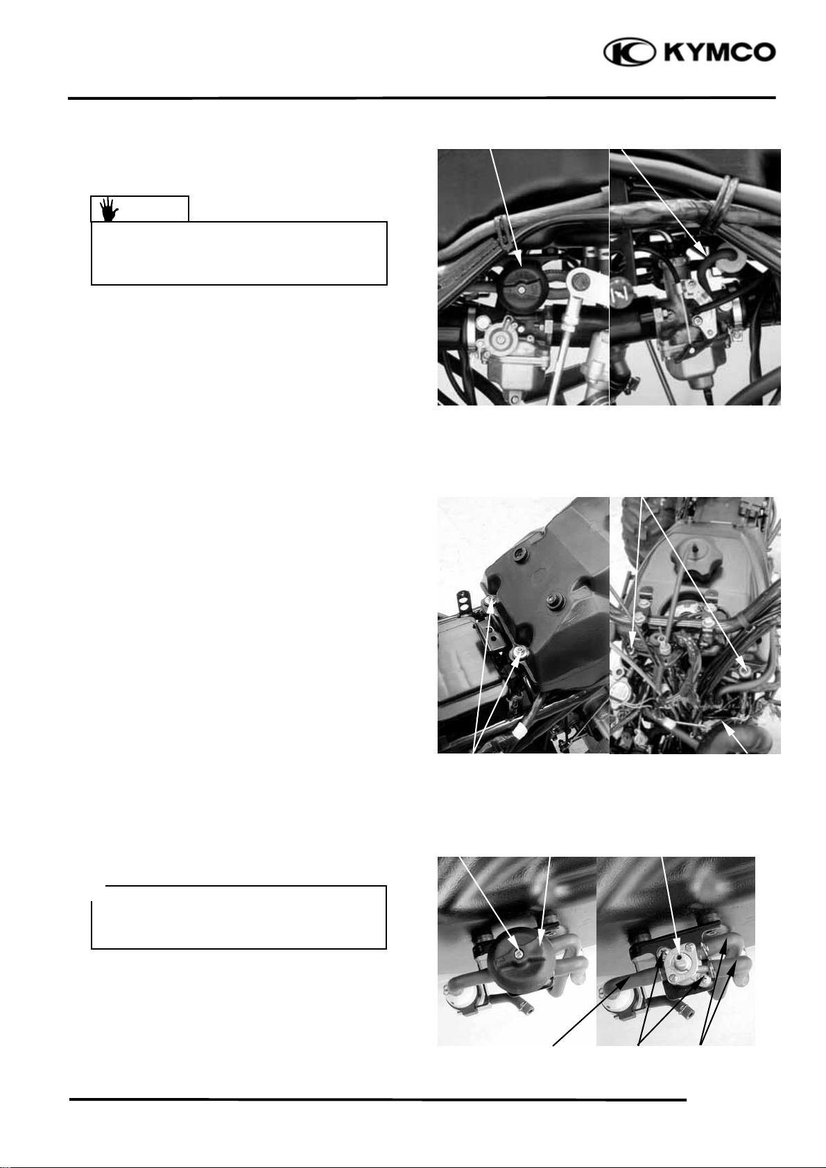
DISASSEMBLY
Remove the two screws on the retaining ring
and then remove retaining ring.
Remove the washer and control shaft.
Remove the rubber gasket from the fuel
valve body.
Screws
Retaining Ring
Rubber Gaske
Control Shaf
Fuel Valve Body
Washe
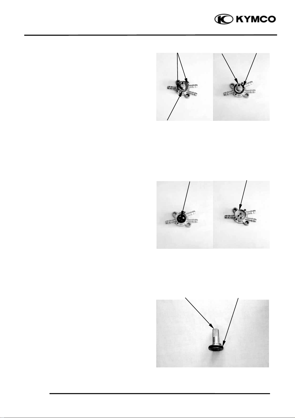
INSPECTION
Inspect the fuel valve body for dirt and clog.
Clean if necessary.
Replace the rubber gasket with new ones if
they are damaged or deteriorated.
Replace the O-rings with new ones if they
are damaged or deteriorated.
Control Shaf
O-ring
5-5
 Loading...