

Page 1

17. LIGHTS/ SWITCHES
17-0
MX’er 50
17
__________________________________________________________________________________
__________________________________________________________________________________
__________________________________________________________________________________
__________________________________________________________________________________
__________________________________________________________________________________
LIGHTS/SWITCHES
__________________________________________________________________________________
SERVICE INFORMATION -------------------------------------------- 17- 2
TROUBLESHOOTING ------------------------------------------------- 17- 2
HEADLIGHT ------------------------------------------------------------ 17- 3
INSTRUMENTS/STOP LIGHT/TAILLIGHT------------------------ 17- 4
IGNITION SWITCH ---------------------------------------------------- 17- 5
STOP SWITCH/OIL METER ------------------------------------------ 17- 5
STARTER BUTTON---------------------------------------------------- 17- 6
HEADLIGHT SWITCH------------------------------------------------- 17- 6
ENGINE STOP SWITCH----------------------------------------------- 17- 7
17
Page 2
17. LIGHTS/ SWITCHES
17-1
MX’er 50
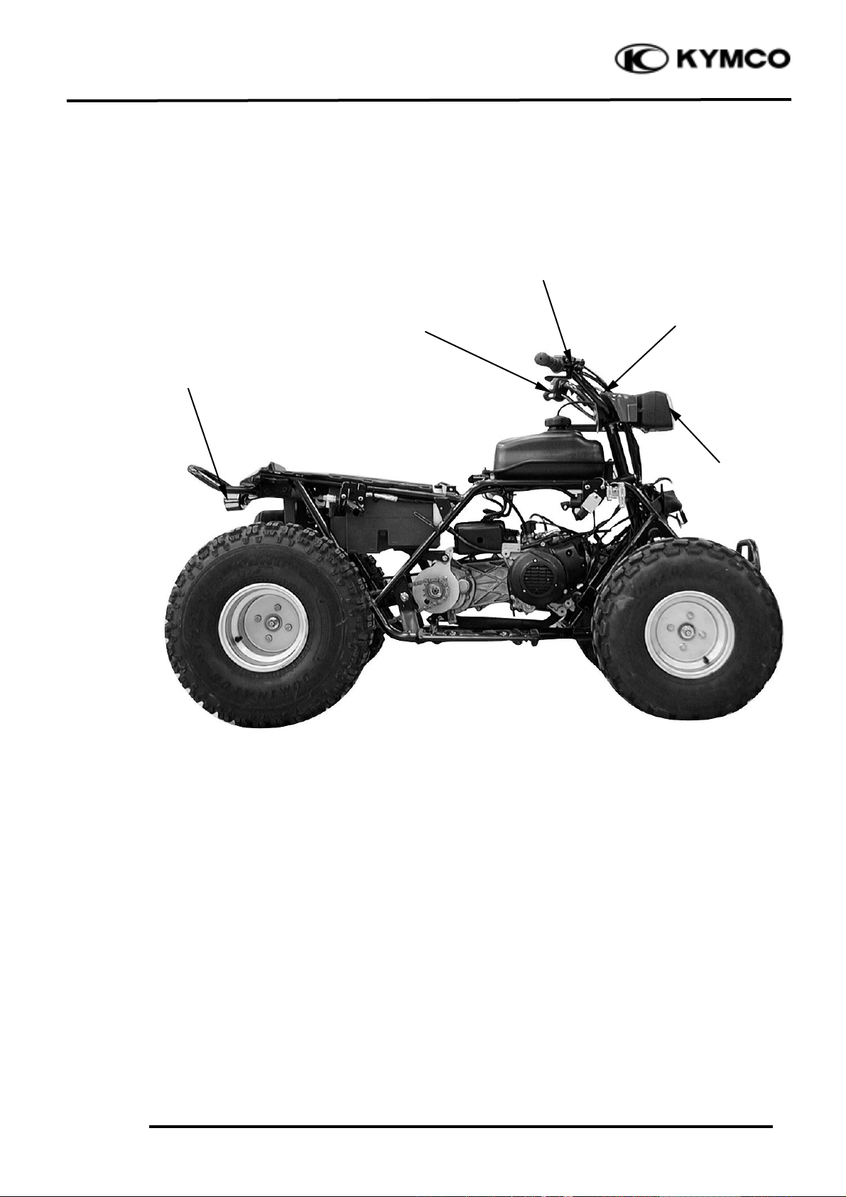
ELECTRICAL EQUIPMENT LAYOUT
Stop Switches
Ignition Switch
Headlight Switch/
Starter Button/Engine
Stop Switch
Headlight
Taillight/Stop
Light
Page 3

17. LIGHTS/ SWITCHES
17-2
MX’er 50
SERVICE INFORMATION
GENERAL INSTRUCTIONS
• An electric tester is needed to measure or test the electric equipment.
• Be sure to use fuses and bulbs of the same specifications to avoid damage of electrical equipment.
• After installation of each switch, a continuity check must be performed. A continuity check can
usually be made without removing the part from the motorcycle.
TROUBLESHOOTING
Lights do not come on Engine starts but stalls during idling
when ignition switch is “ON” • Clogged carburetor
• Faulty ignition switch
• Fuse burned out
• Weak battery
• Burned bulb
• Faulty switch
• Poorly connected, broken or shorted wire
Page 4

17. LIGHTS/ SWITCHES
17-3
MX’er 50
HEADLIGHT
BULB REPLACEMENT
Disconnect the cover of the ignition switch
and remove the two headlight attaching
bolts.
Remove the headlight and disconnect the
headlight wire coupler.
Remove the two headlight case attaching
screws and disconnect the headlight.
Check the bulb for damage and replace with
a new one if necessary.
Disconnect the headlight wire coupler.
Remove the rubber boot.
Push and disconnect the spring from the
headlight cover.
Screws
Bolts
Cover
Screws
Headlight Wire Coupler
Rubber Boot
Page 5

17. LIGHTS/ SWITCHES
17-4
MX’er 50
Remove the headlight bulb
INSTALLATION
Install the headlight in the reverse order of
removal.
INSTRUMENTS
REMOVAL
Remove the two headlight attaching bolts.
Remove the headlight and disconnect the
headlight wire coupler.
Remove the two headlight case attaching
screws and disconnect the headlight.
Remove the light shell, rubber boot and bulb
socket.
Check the bulb for damage and replace with
a new one if necessary.
INSTALLATION
The installation sequence is the reverse of
removal.
STOP LIGHT/TAILLIGHT
Remove the two taillight shell screws and
the shell.
Headlight Bulb
Light Shell
Taillight Shell Screws
After installation, adjust the headlight
beam.
°Ø
Bulb Socket
Rubber Boot
Taillight Shell
Page 6

17. LIGHTS/ SWITCHES
17-5
MX’er 50
Remove the bulb and check the bulb for
damage. Replace with a new one if
necessary.
IGNITION SWITCH
Check for continuity between the wires
indicated below.
Color
Position
Black
Red
Black/
White
Green
OFF°≥°≥
ON°≥°≥
STOP SWITCH
Disconnect the front stop switch wire
coupler.
Check for continuity between the front stop
switch wires.
Brake lever applied: There is continuity.
Brake lever released: There is no continuity.
OIL METER
Remove the seat. (!2-3)
Disconnect the oil meter wire connectors
and remove the oil meter. Keep the oil
meter float at the lower position (the oil
meter is ON).
Measure the resistances between the wire
terminals as Å and Ç shown in the left
figure.
Bulb
Oil Meter Wire
Oil Meter
Page 7

17. LIGHTS/ SWITCHES
17-6
MX’er 50
Wire Terminals
Resistance
Black/Red(+)_ Green(-)
26KW
Green(-)_ Black(+)
°¤
Oil Meter Operation Inspection
Measure the resistance between the wire
terminals with the float at upper position
(the oil meter is OFF).
Black/Red(+)_ Black(-)
°¤
STARTER BUTTON
Remove the center cover.
Disconnect the starter button yellow/brown
and yellow/red wires.
Check for continuity between the black and
yellow/red wires.
Color
Position
Green
Yellow/Red
FREE
PUSH°≥°≥
HEADLIGHT SWITCH
Remove the center cover.
Disconnect the headlight switch wire
coupler. Check for continuity between the
headlight switch wires.
Color
Position
Yellow
White
Blue
Pink
°≥
°≥
°≥
°≥
°≥
°≥
Green
Yellow/ Red
Starter Button
Yellow
Blue
White
Pink
Headlight Switch
Oil Meter
Float
B/R
Ç
Å
GBG
Before removing the oil meter, be sure to
drain the motor oil and do not allow
sparks or flames near the working area.
°Ø
Before performing the following test,
operate the turn signals to determine
that the battery circuit is normal.
°Ø
Page 8

17. LIGHTS/ SWITCHES
17-7
MX’er 50
ENGINE STOP SWITCH
Remove the center cover.
Disconnect the headlight switch wire
coupler. Check for continuity between the
headlight switch wires.
Color
Position
Blue/Yellow
Green
°≥
°≥
Blue/Yellow
Green
Engine Stop Switch
 Loading...