

Page 1

12. FRONT WHEEL/FRONT BRAKE/FRONT
SUSPENSION/STEERING SYSTEM
12-0
MX’er 50
12
__________________________________________________________________________________
__________________________________________________________________________________
__________________________________________________________________________________
__________________________________________________________________________________
__________________________________________________________________________________
FRONT WHEEL/FRONT BRAKE/
FRONT SUSPENSION\STEERING SYSTEM
__________________________________________________________________________________
SERVICE INFORMATION -------------------------------------------- 12- 2
TROUBLESHOOTING ------------------------------------------------- 12- 3
FRONT WHEEL--------------------------------------------------------- 12- 4
FRONT BRAKE --------------------------------------------------------- 12- 7
FRONT SUSPENSION ------------------------------------------------- 12- 9
STEERING SYSTEM--------------------------------------------------- 12-13
12
Page 2

12. FRONT WHEEL/FRONT BRAKE/FRONT
SUSPENSION/STEERING SYSTEM
12-1
MX’er 50
Page 3
12. FRONT WHEEL/FRONT BRAKE/FRONT
SUSPENSION/STEERING SYSTEM
12-2
MX’er 50
SERVICE INFORMATION
GENERAL INSTRUCTIONS
• Remove the machine frame covers before removing the front wheel. Jack the machine front wheel
off the ground and be careful to prevent the machine from falling down.
• During servicing, keep oil or grease off the brake drum and brake linings.
• Inspect the brake system before riding.
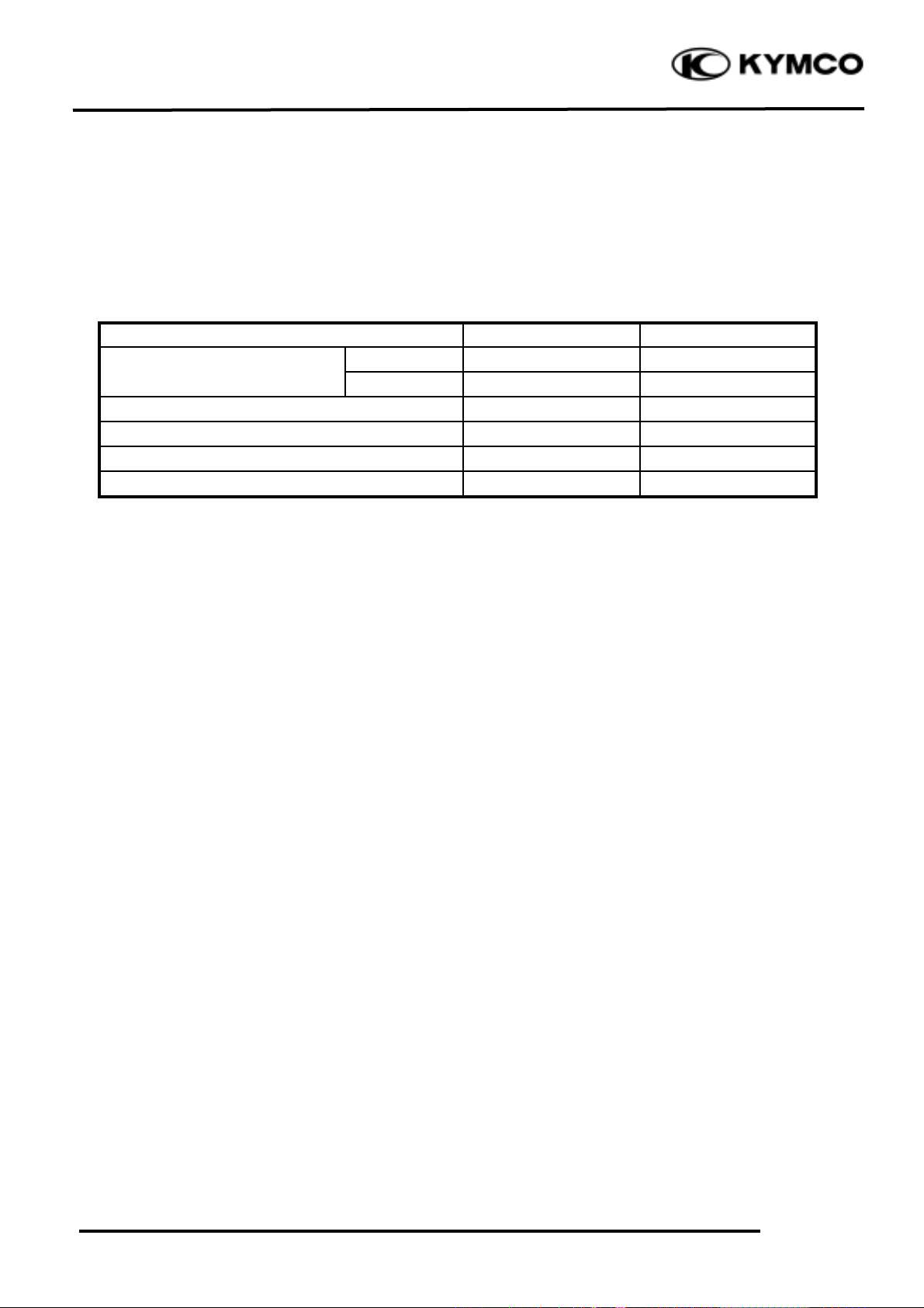
SPECIFICATIONS
Item
Standard (mm)
Service Limit (mm)
Radialæ2.0
Axialæ2.0
Front brake drum I.D
110
111
Front brake lining thickness
4
1.5
Tie rod length
266.5
æ
Rod-end (tie rod) angle
180ºæ
TORQUE VALUES
Steering stem nut 6.0_ 8.0kgf-m
Swing arm nut 4.0_ 5.0kgf-m
Front wheel nut 6.0_ 8.0kgf-m
Front wheel hub nut 6.0_ 8.0kgf-m
Front shock absorber upper
mount bolt 3.5_ 4.5kgf-m
Front shock absorber lower
mount bolt 3.5_ 4.5kgf-m
Front wheel rim run out
Page 4

12. FRONT WHEEL/FRONT BRAKE/FRONT
SUSPENSION/STEERING SYSTEM
12-3
MX’er 50
SPECIAL TOOLS
Oil seal and bearing install E014
TROUBLESHOOTING
Hard steering (heavy) Front wheel wobbling
•Insufficient tire pressure • Bent rim
• Excessive wheel bearing play
• Bent spoke plate
• Faulty tire
Steers to one side or does not track straight • Improperly tightened axle nut
• Uneven front shock absorbers Soft front shock absorber
• Bent front arm • Weak shock springs
• Bent steering knuckle • Insufficient damper oil
Poor brake performance Front shock absorber noise
• Incorrectly adjusted brake • Slider bending
• Worn brake linings • Loose arm fasteners
• Contaminated brake lining surface • Lack of lubrication
• Worn brake shoes at cam contacting area
• Worn brake drum
• Poorly connected brake arm
Page 5
12. FRONT WHEEL/FRONT BRAKE/FRONT
SUSPENSION/STEERING SYSTEM
12-4
MX’er 50
FRONT WHEEL
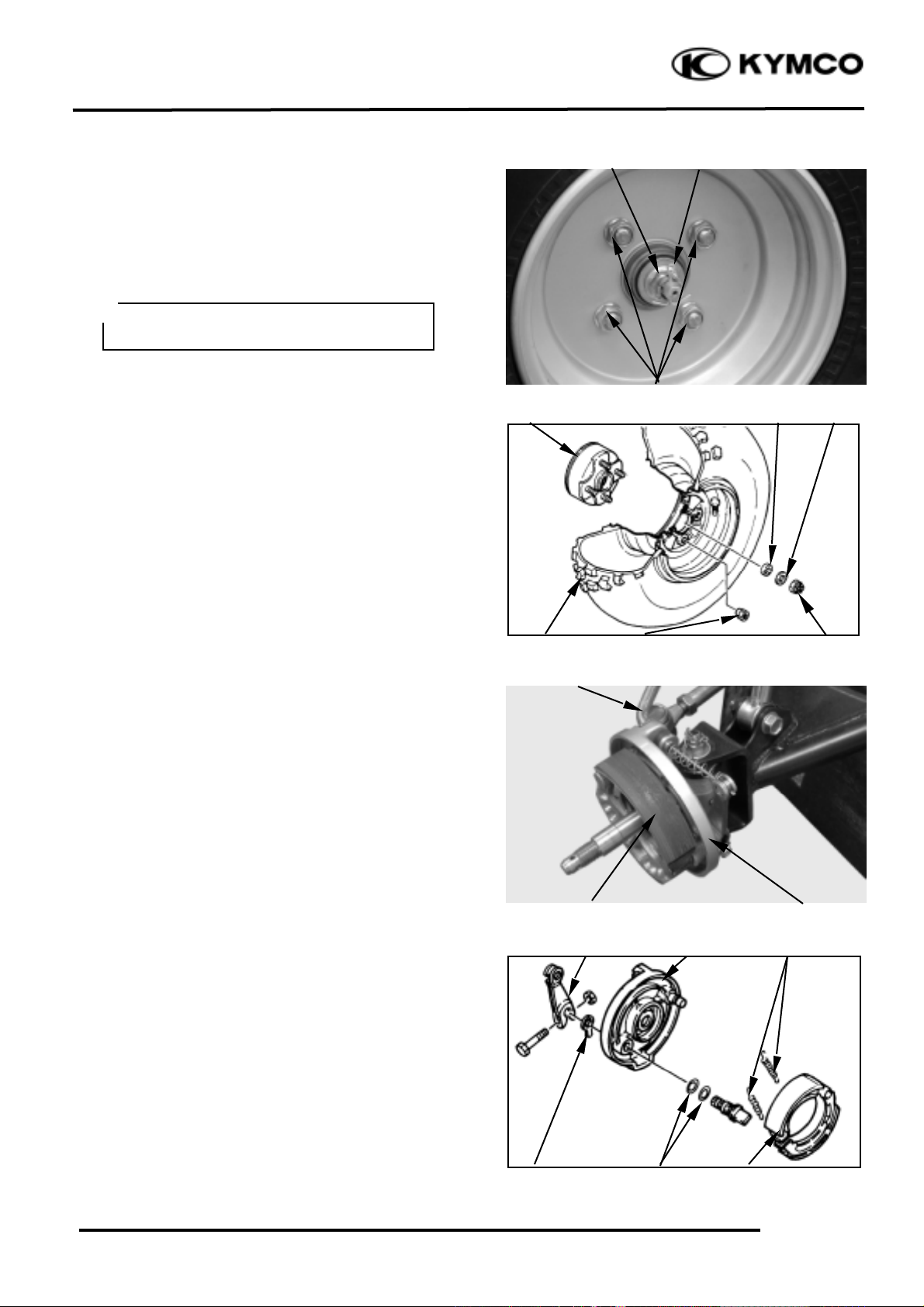
REMOVAL
Place the machine on a level place.
Remove four nuts attaching the wheel panel
and front wheel.
Elevate the front wheels by placing a
suitable stand under the frame.
Remove the cotter pin.
Remove nut attaching the wheel hub and
washer.
Remove the collar and wheel hub.
FRONT BRAKE DISASSEMBLY
Loosen the lock nut and tighten the adjuster
nut at brake lever. (Refer to the “FRONT
BRAKE ADJUSTMENT” section in the
CHAPTER 3.).
Disconnect the front brake cable from brake
cam lever and remove the brake panel.
Remove the brake shoes.
REMOVE
Remove brake shoes and springs.
Remove the bolt attaching camshaft lever
and remove camshaft lever.
Remove the wear indicator, camshaft and O-
rings
Pin
Nut
Camshaft lever
Brake Cable
Brake Panel
Support the machine securely so there is
no danger of it falling over.
°Ø
Wheel Hub
Front Wheel
Wheel Panel Nuts
Collar
Hub Nut
Nuts
Washer
Wear
Indicator
Brake Panel
Brake Shoes
O-rings
Springs
Brake Shoes
Page 6
12. FRONT WHEEL/FRONT BRAKE/FRONT
SUSPENSION/STEERING SYSTEM
12-5
MX’er 50
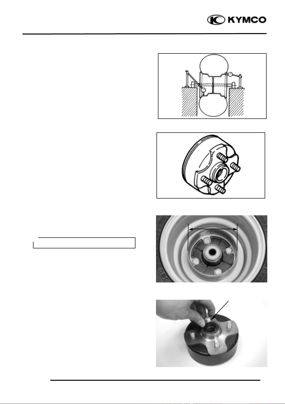
Measure the wheel run out.
Replace wheel or check bearing play if out
of specification
Rim run out limits:
Vertical: 2.0mm
Lateral: 2.0mm
Inspect the front wheel hub.
Replace if cracks or damage.
Inspect the front brake drum.
Measure the front brake drum I.D.
Service limits: 111mm
FRONT WHEEL BEARING
Remove the side collar.
Side Collar
Keep oil or grease off the brake drum.
°Ø
Page 7

12. FRONT WHEEL/FRONT BRAKE/FRONT
SUSPENSION/STEERING SYSTEM
12-6
MX’er 50
Remove the dust seal.
Turn the inner race of each bearing with
your finger to see if they turn smoothly and
quietly. Also check if the outer race fits
tightly in the hub.
BEARING REPLACEMENT
Remove the front wheel bearings and
distance collar.
Replace the bearings if the races do not turn
smoothly, quietly, or if they fit loosely in
the hub.
Apply grease to a new dust seal lip and
install the dust seal.
Pack all bearing cavities with grease.
Drive in the left bearing.
Install the distance collar.
Drive in the right bearing.
Oil seal and bearing install E014
Dust Seal
Wheel Bearing
Driver Handle
Dust Seal
Side Collar
Collar
Outer Driver
• Do not allow the bearings to tilt
while driving them in.
• Drive in the bearing squarely
with the sealed end facing out.
°Ø
Special
Page 8

12. FRONT WHEEL/FRONT BRAKE/FRONT
SUSPENSION/STEERING SYSTEM
12-7
MX’er 50
FRONT BRAKE
FRONT BRAKE LINING INSPECTION
Measure the front brake lining thickness.
Service limit: 2.0mm replace if below
REMOVAL
Inspect the shoe springs, O-rings, camshaft
lever and wear indicator.
Replace if damage.
Inspect the brake shoe plate.
Replace if cracks or damage.
Inspect the brake shoe pivot pin.
Replace if wear or damage.
Inspect the camshaft hole and camshaft.
Replace if scratches or excessive wear.
INSTALLATION
Reverse the “REMOVAL” procedures.
Tighten the bolt for camshaft lever.
Torque: 1.8_ 2.5kgf-m
Brake Lining
Apply the grease onto the o-ring, oil seal
lips, pivot pin of brake shoe and
camshaft.
°Ø
• Install the camshaft to the brake
shoe plate with the slot of the camshaft
placing at bass line of the wear indicator
scale.
• Align the projection with the slot
of the camshaft when installing the
wear indicator to the camshaft.
• Align the cut-out of the camshaft
lever with the slot of the camshaft
when installing the camshaft lever to
the camshaft.
°Ø
Camshaft lever
Wear
Indicator
Brake Plate
O-rings
Springs
Oil Seal
Camshaft Hole
Brake shoe pivot pin
Camshaft
Keep oil or grease off the brake linings.
°Ø
Page 9

12. FRONT WHEEL/FRONT BRAKE/FRONT
SUSPENSION/STEERING SYSTEM
12-8
MX’er 50
Install the brake shoe plate.
Apply the grease onto the bearings and oil
seal lips of the wheel hub.
Install wheel hub, plate washer and tight the
nut (wheel hub).
Torque: 6.0_ 8.0kgf-m
Install cotter pins.
Install the front wheel and tighten the nuts
(wheel).
Torque: 6.0_ 8.0kgf-m
Adjust the front brake cable free play.
Refer to the “FRONT BRAKE
ADJUSTMENT” section in the
CHAPTER 3.
Brake cable free play: 10_ 20mm at lever
pivot.
Do not loosen the axle nut after torque
tightening. If the axle nut groove id not
aligned with the cotter pin hole, align
groove with the hole by tightening ut on
the axle nut.
°Ø
Tapered wheel nuts are used for front
wheels.
Install the nuts with its tapered side
towards the wheel.
°Ø
Make sure that the boss on the knuckle
correctly engages with the locating slot
on the brake shoe plate.
°Ø
Always use a new cotter pin.
°Ø
Boss
Locating Slot
Page 10

12. FRONT WHEEL/FRONT BRAKE/FRONT
SUSPENSION/STEERING SYSTEM
12-9
MX’er 50
FRONT SUSPENSION
REMOVAL
Elevate the front wheels by placing a
suitable stand under the frame.
Remove the front wheel, wheel hub, brake
shoe plate.
Remove the upper and lower bolt, then
remove the shock absorber.
Remove the cotter pin and nut, then remove
tie-rod from steering knuckle.
Remove cotter pin, nut, washer and bolt,
then remove the steering knuckle, covers,
collar and bush from the front arm.
Upper Bolt
Lower Bolt
Support the machine securely so there is
no danger of it falling over.
°Ø
Tie-rod
Nut
Cotter pin
Steering Knuckle
Front arm
Cotter pin
Nut
Bolt
Washer
Steering Knuckle
Bush
Bush
Cover
Cover
Collar
Page 11

12. FRONT WHEEL/FRONT BRAKE/FRONT
SUSPENSION/STEERING SYSTEM
12-10
MX’er 50
INSPECTION
Check the front arm brackets of the frame.
If bent, cracked or damaged, repair or
replace the frame.
Check the tightening torque of the front
arms securing nuts.
Torque: 4.0_ 5.0kgf-m
Check the front arm side play by moving it
from side to side.
If side play noticeable, replace the inner
collar, bushings and thrust covers as a set.
Check the front arm vertical movement by
moving it up and down.
If vertical movement is tight, binding or
rough, replace the inner collar, bushings and
thrust covers as a set.
Remove the two nut and two bolt attaching
the front arm, then remove the front arm.
INSPECTION
Inspect the shock absorber rod.
Replace the shock absorber assembly if
bends or damage.
Inspect the shock absorber.
Replace the shock absorber assembly if oil
leakes.
Inspect the spring of the shock absorber by
move the spring up and down.
Replace the shock absorber assembly if
fatigue.
Bolt
Bush
Front Arm
Bush
Nuts
Bolt
Bush
Page 12

12. FRONT WHEEL/FRONT BRAKE/FRONT
SUSPENSION/STEERING SYSTEM
12-11
MX’er 50
Inspect the steering knuckle.
Replace if cracks, pitting or damage.
.
Inspect the front arm.
Replace if cracks, bends or damage.
Inspect bushes.
Replace if wear or damage.
INSTALLATION
Reverse the “REMOVAL” procedures.
Install the front arm nut onto the frame and
tighten the nuts.
Torque: 4.0_ 5.0kgf-m
Do not attempt to straighten a bent arm,
this may dangerously weaken the arm.
°Ø
Apply the grease onto the bushes, collars
and covers.
°Ø
Bushes
Page 13

12. FRONT WHEEL/FRONT BRAKE/FRONT
SUSPENSION/STEERING SYSTEM
12-12
MX’er 50
Apply the grease onto the bush, collars and
covers, then install the steering knuckle onto
the front arm and tighten the nut.
Torque: 4.0_ 5.0kgf-m
Install the cotter pin and band ends of cotter
pin.
Install the tie-rod onto the steering knuckle
and tighten the nut.
Torque: 4.0_ 5.0kgf-m
Install the cotter pin and band ends of cotter
pin.
Install the shock absorber and tighten the
upper and lower bolts.
Torque: 3.5_ 4.5kgf-m
Install the brake shoe plate, wheel hub and
front wheel.
Refer to the “FRONT WHEEL
INSTALLATION” section.
Bleed Valve
Always use a new cotter pin.
°Ø
Always use a new cotter pin.
°Ø
Page 14

12. FRONT WHEEL/FRONT BRAKE/FRONT
SUSPENSION/STEERING SYSTEM
12-13
MX’er 50
STEERING SYSTEM
REMOVAL
Remove the following parts:
Seat, Front cover, Center cover and Front
fender
Refer to the “FENDERS” section in the
CHAPTER 2
Disconnect the main switch lead.
Remove the handlebar cover with main
switch.
Disconnect the front brake cables from the
brake lever, rear brake cable from the brake
lever and brake switch from the bracket of the
brake lever.
Remove the two screws to remove the cover
of the throttle housing.
Disconnect the throttle cable from the lever.
Brake Switch
Hook
Front Brake Cables
Handlebar Cover
Main Switch Lead
Rear Brake Cable
Disconnect the brake switch from the
bracket of the brake lever while pushing
the hook of the brake switch with a
driver.
°Ø
Screws
Cover
Throttle Housing
Page 15

12. FRONT WHEEL/FRONT BRAKE/FRONT
SUSPENSION/STEERING SYSTEM
12-14
MX’er 50
Remove the two screws and remove the
handlebar switch.
Remove the two bolts and remove headlight
unit.
Remove the four handlebar holder bolts and
remove the handlebar.
Remove the cotter pins and nuts attaching
the tie-rods, then remove tie-rods.
Remove the cotter pin and nut attaching the
steering column, then remove steering
column and collar.
Handlebar Switch
Screws
Bolts
Headlight Unit
Bolts
Handlebar
Cotter Pin
Cotter Pin
Nut
Nut
Tie-rod
Cotter Pin
Nut
Page 16

12. FRONT WHEEL/FRONT BRAKE/FRONT
SUSPENSION/STEERING SYSTEM
12-15
MX’er 50
Remove the two bolts to remove the cable
holder, steering bracket, collars and steering
column.
INSPECTION
Inspect the handlebar.
Replace if cracks, bends or damage.
Inspect the steering column.
Replace if bends or damage.
Inspect the steering brackets and oil seal.
Replace if wear or damage.
Bolts
Do not attempt to straighten a bent
shaft, this may dangerously weaken the
shaft.
°Ø
Cable Holder
Collar
Steering Bracket
Steering Column
Steering Brackets
Oil Seal
Page 17

12. FRONT WHEEL/FRONT BRAKE/FRONT
SUSPENSION/STEERING SYSTEM
12-16
MX’er 50
Inspect the tie-rod.
Replace if bend or damage.
Check the tie-rod end movement.
Replace if the tie-rod end exists free play or
turns roughly.
Check the tapered surface of the tie-rod end.
Replace if pitting, wear or damage.
Adjust the tie-rod length.
Adjustment steps:
(The following procedures are done on both
tie-rods, right and left.)
Loosen the lock nuts.
Adjust the tie-rod length by tuning both tie-
rod ends.
Tie rod length: 266.5mm
Set the rod-end (steering column side) in an
angle where the indentation surface of the
tie-rod is parallel to the rod-end shaft, and
then tighten the lock nut.
Torque: 2.5_ 3.5kgf-m
Set the other rod-end (knuckle arm side) in
an angle as shown (right-hand tie-rod and
left-had tie-rod), and then tighten the lock
nut.
Rod-end (tie rod) angle: 180
º
Torque: 2.5_ 3.5kgf-m
Lock Nut
To Steering Column
To Knuckle Arm
After making adjustment on both tie rods
be sure to mark them R and L for
identification.
°Ø
Lock Nut
Indentation Surface
Page 18

12. FRONT WHEEL/FRONT BRAKE/FRONT
SUSPENSION/STEERING SYSTEM
12-17
MX’er 50
Inspect the collar, duty seal, snap ring and
bearing.
Replace if wear or damage.
INSTALLATION
Reverse the “REMOVAL” procedures.
Assembly the steering column and tighten
the two bolts.
Torque: 1.8_ 2.5kgf-m
Band the lock washer tabs.
The threads on both rod-end must be of
the same length.
°Ø
Apply the grease onto the collar, duty
seal, and bearing.
°Ø
Collar
Snap Ring
Bearing
Dust Seal
Dust Seal
Page 19

12. FRONT WHEEL/FRONT BRAKE/FRONT
SUSPENSION/STEERING SYSTEM
12-18
MX’er 50
Install the steering column and collar, then
tighten the nut.
Torque: 6.0_ 8.0kgf-m
Install the cotter pin and band ends of cotter
pin.
Install the tie rods and tighten the nut.
Torque: 4.0_ 5.0kgf-m
Install the cotter pin and band ends of cotter
pin.
Install handlebar and handlebar holder, then
tighten the four bolts.
Torque: 1.8_ 2.5kgf-m
Be sure that the rod-end on the
indentation surface side is connected to
the steering column.
°Ø
Always use a new cotter pin.
°Ø
Always use a new cotter pin.
°Ø
Indentation Surface
Bolts
Headlight Unit
Bolts
Handlebar
Cotter Pin
Cotter Pin
Nut
Nut
Tie-rod
Cotter Pin
Nut
Page 20

12. FRONT WHEEL/FRONT BRAKE/FRONT
SUSPENSION/STEERING SYSTEM
12-19
MX’er 50
Apply the grease onto the end of the
throttle cable and end of the brake cable.
Refer to the “TOE-IN ADJUSTMENT”
section in the CHAPTER 3 to adjust toe-in.
Refer to the “FRONT BRAKE
ADJUSTMENT” section in the CHAPTER
3 to adjust front brake.
Refer to the “REAR BRAKE
ADJUSTMENT” section in the CHAPTER
3 to adjust rear brake.
• Be sure the upper handlebar
holder mark face to front.
• Fist tighten the bolts on the front
side of the handlebar holder, and then
tighten the bolts on the rear side.
°Ø
 Loading...