

Page 1

11. CRANKSCASE/CRANKSHAFT/
BALANCE SHAFT
11-0
MX’er SYSTEM
11
__________________________________________________________________________________
__ ___ ___ ___ ___ ___ ___ ___ __ _ __ _ __ ___ ___ ___ ___ ___ ___ ___ ___ ___ ___ ___ __ _ __ _ __ ___ ___ ___ _
__ ___ ___ ___ ___ ___ ___ ___ __ _ __ _ __ ___ ___ ___ ___ ___ ___ ___ ___ ___ ___ ___ __ _ __ _ __ ___ ___ ___ _
__ ___ ___ ___ ___ ___ ___ ___ __ _ __ _ __ ___ ___ ___ ___ ___ ___ ___ ___ ___ ___ ___ __ _ __ _ __ ___ ___ ___ _
__ ___ ___ ___ ___ ___ ___ ___ __ _ __ _ __ ___ ___ ___ ___ ___ ___ ___ ___ ___ ___ ___ __ _ __ _ __ ___ ___ ___ _
CRANKCASE/CRANKSHAFT/BALANCE SHAFT
__ ___ ___ ___ ___ ___ ___ ___ __ _ __ _ __ ___ ___ ___ ___ ___ ___ ___ ___ ___ ___ ___ __ _ __ _ __ ___ ___ ___ _
SERVICE INFORMATION -------------------------------------------- 11- 2
TROUBLESHOOTING ------------------------------------------------- 11- 2
CRANKCASE SEPARATION ----------------------------------------- 11- 3
CRANKSHAFT INSPECTION----------------------------------------- 11- 4
CRANKCASE/BALANCE SHAFT ASSEMBLY -------------------- 11- 5
11
Page 2
11. CRANKCASE/CRANKSHAFT/
BALANCE SHAFT
11-1
MX’er SYSTEM
Page 3
11. CRANKSCASE/CRANKSHAFT/
BALANCE SHAFT
11-2
MX’er SYSTEM
SERVICE INFORMATION
GENERAL INSTRUCTIONS
• This section covers crankcase separation to service the crankshaft. The engine must be removed
for this operation.
• The following parts must be removed before separating the crankcase.
-Cylinder head (!Section 7)
-Cylinder/piston (!Section 8)
-Drive and driven pulleys (!Section 9)
-A.C. generator (!Section 4)
-Carburetor/air cleaner (!Section 5)
-Starter motor (!Section 16)
-Oil pump (!Section 4)
SPECIFICATIONS
Item
Standard (mm)
Service Limit (mm)
Connecting rod big end side clearance
0.10_ 0.35
0.55
Crankshaft
Connecting rod big end radial clearance
0_ 0.008
0.05
Run outæ0.10
TORQUE VALUES
Crankcase bolt 0.8_ 1.2kgf-m
Cam chain tensioner slipper bolt 0.8_ 1.2kgf-m
Cam chain cover bolt 0.8_ 1.2kgf-m
TROUBLESHOOTING
Excessive engine noise
Excessive bearing play
Page 4

11. CRANKCASE/CRANKSHAFT/
BALANCE SHAFT
11-3
MX’er SYSTEM
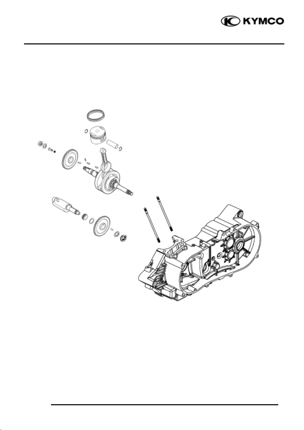
CRANKCASE SEPARATION
Remove the left and right crankcase
attaching bolts. (Section 10)
Separate the left and right crankcase halves.
Remove the gasket and dowel pins.
Remover balance shaft from the left
crankcase.
Dowel Pins
Crankcase Bolts
Gasket
Do not damage the crankcase gasket
surface.
*
Balance Shaft
Crankshaft
Page 5

11. CRANKSCASE/CRANKSHAFT/
BALANCE SHAFT
11-4
MX’er SYSTEM
Remove the crankshaft and cam chain from
the left crankcase.
Clean off all gasket material from the
crankcase mating surfaces.
CRANKSHAFT INSPECTION
Measure the connecting rod small end I.D.
Service Limit: 15.06 mm replace if over
Measure the connecting rod big end side
clearance.
Service Limit: 0.55mm replace if over
Gasket
Avoid damaging the crankcase mating
surfaces.
*
Page 6

11. CRANKCASE/CRANKSHAFT/
BALANCE SHAFT
11-5
MX’er SYSTEM
Turn the crankshaft bearings and check for
excessive play.
Measure the crankshaft bearing play.
Service Limit:
Axial : 0.20mm replace if over
Radial : 0.05mm replace if over
Measure the crankshaft run out.
Service Limit: 0.10mm replace if over
CRANKCASE/BALANCE SHAFT
ASSEMBLY
Install the cam chain into the left crankcase.
Install the crankshaft and balance shaft into
the left crankcase.
Install the right and left crankcase.(10-8)
Tighten crankcase attach bolts.
Right Crankcase
Play
Play
Radial
Axial
Crankshaft
Balance Shaft
Left Crankcase
Page 7

11. CRANKSCASE/CRANKSHAFT/
BALANCE SHAFT
11-6
MX’er SYSTEM
Align the mark on the balance gear with the
mark on the crankshaft gear.
Install the right and left case cover.
.
Install the cylinder.
Mark
Right Case
 Loading...